
Gigabyte MW21-SE0 (rev. 1.0) Инструкция онлайн
1
2 3
4
5
6
7
8
9
11
10
12
13
14
151617181920
22
21
23
24
25
26
27
28
29
30
35
31
32
33
37 38
34
36
HDD Back Plane Board Header/ 硬盤背板排針
Front Panel Header/ 前面板
1
2423
2
1 2
9 10
No. Pin Define
1 HDD LED+
2 Power LED+
3 HDD LED-
4 Power LED-
5 GND
6 Power Buon+
7 Reset Buon
8 Power Buon-
9 No Connect
10 No Pin
No. Pin Define
1 Power LED+
3 No Pin
5 Power LED-
7 HDD LED+
9 HDD LED-
11 Power Buon
13 GND
15 Reset Buon+
17 GND
19 ID Switch+
21 ID Switch-
23 NMI Switch-
No. Pin Define
2 5V Standby
4 ID LED+
6 ID LED-
8 System Front Board LED+
10 System Status LED-
12 LAN1 Acve LED+
14 LAN1 Link LED-
16 SMBus Data
18 SMBus Clock
20 Case Open
22 LAN2 Acve LED
24 LAN2 Link LED-
ATX Power/ 电源
PMBUS
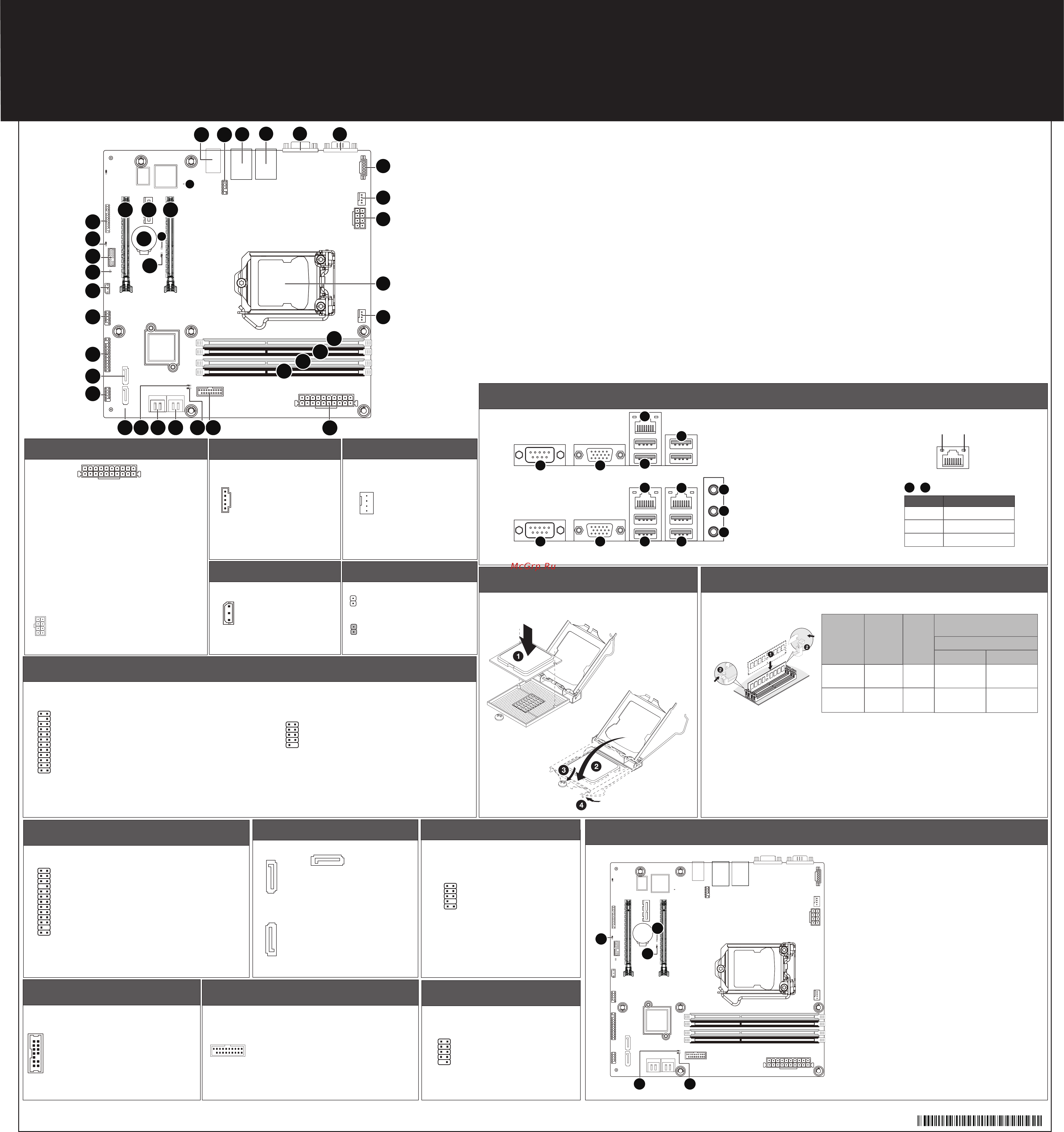
Installing CPU/ 安装 CPU Memory Populaon Configuraon/ 安装内存
Type
Ranks Per
DIMM and
Data Width
Speed (MT/s);
Slot Per Channel (SPC) and
DIMM Per Channel (DPC)
UDIMM
Unbuffered
DDR4 ECC
UDIMM
Unbuffered
DDR4 non-ECC
SR, DR 1.2V
1.2V
2133 2133
Supported
Voltage
DR
2133 2133
2 Slot Per Channel
1DPC 2DPC
Rear I/O Connector/ 后面板接口
Off
State Description
Yellow On 1Gbps data arte
Green On 100Mbps data arte
10Mbps data arte
SATA Connector/SATA 接口
1
7
7
1
7 1
No. Pin Define
1 GND
2 TXP
3 TXN
4 GND
5 RXN
6 RXP
7 GND
TPM Connector/ 可信平台模块
IPMB
1
3
No. Pin Define
1 Clock
2 GND
3 Data
CPU/System FAN/ 风扇
USB 2.0 Header
USB 3.0 Header
1
20
10
11
No. Pin Define
1 Power
2 IntA_P1_SSRX-
3 IntA_P1_SSRX+
4 GND
5 IntA_P1_SSTX-
6 IntA_P1_SSTX+
7 GND
8 IntA_P1_D-
9 IntA_P1_D+
10 NC
No. Pin Define
11 IntA_P2_D+
12 IntA_P2_D-
13 GND
14 IntA_P2_SSTX+
15 IntA_P2_SSTX-
16 GND
17 IntA_P2_SSRX+
18 IntA_P2_SSRX-
19 Power
20 No Pin
Front Audio Connector/ 前置音频
Case Open Intrusion Header
Jumper Sengs/ 跳线设置
1
2
3
4
5
No. Desripon
1 Clear CMOS Jumper
Open: Normal operaon (Default seng)
Close: Clear CMOS data.
2 ME Update Jumper
1-2 Close: Normal operaon (Default seng)
2-3 Close: ME update.
3 S3 Power On Select Jumper (MW21-SE1 Only)
1-2 Close: Stop an inial power on when BMC is not ready.
2-3 Close: Keep inial power on. (Default seng)
4 Clearing Supervisor Password Jumper
1-2 Close: Normal operaon. (Default seng)
2-3 Close: Skip supervisor password.
5 ME Recovery Jumper
1-2 Close: Normal operaon. (Default seng)
2-3 Close: ME recovery mode.
4
2
2
3
3
4
4
4
4
6
7
8
5
5
1
1
MW21-SE0/MW21-SE1 Quick Reference Guide/ 快速测试参考指南
1
4
1
5
15
48
1 2
13 14
1 2
21
109
25 26
No. Pin Define
1 3.3V
2 3.3V
3 GND
4 +5V
5 GND
6 +5V
7 GND
8 Power Good
9 5VSB
10 +12V
11 +12V
12 3.3V
No. Pin Define
1 GND
2 GND
3 GND
4 GND
No. Pin Define
1 PMBus Clock
2 PMBus Data
3 PMBus Alert
4 GND
5 3.3V Sense
No. Pin Define
1 GND
2 +12V
3 Sense
4 Speed Control
MW21-SE1
For MW21-SE1 Only
For MW21-SE1 Only
For MW21-SE1 Only
For MW21-SE1 Only
MW21-SE0
No. Pin Define
1 Clock
2 P_3V3_AUX
3 LPC_RST
4 P3V3
5 LPC_LAD0
6 IRQ_SERIAL
7 LPC_LAD1
Open: Normal operaon.
Closed: Acve chassis intruson alert.
No. Pin Define
1 MIC2_L
2 GND
3 MC2_R
4 P3V3
5 LINE2_R
6 MIC2_JD
7 F_Audio_Sense
8 No Pin
9 LINE2_L
10 LINE2_JD
No. Pin Define
1 Power (5V)
2 Power (5V)
3 USB DX-
4 USB DY-
5 USB DX+
6 USB DY+
7 GND
8 GND
9 No Pin
10 No Connect
No. Code Descripon
1 USB_LAN1 LAN port #1 (top) / USB 3.0 ports (boom) (MW21-SE1)
USB_LAN1 USB 3.0 ports (boom) (MW21-SE0)
2 USB_LAN2 LAN port #2 (top) / USB 3.0 ports (boom)
3 VGA_1 VGA port
4 COM1 Serial port
5 PMBUS PMBus connector (MW21-SE1 Only)
6 SYS_FAN1 System fan connector#1
7 P12V_AUX 8 pin power connector
8 CPU0 Intel LGA1151 Socket H4
9 CPU0_FAN CPU fan connector
10 DIMM_P0_A0 Channel 1 slot 0
11 DIMM_P0_A1 Channel 1 slot 1
12 DIMM_P0_B0 Channel 2 slot 0
13 DIMM_P0_B1 Channel 2 slot 1
14 ATX1 24 pin main power connector
15 F_USB3 USB 3.0 header
16 ME_RCVR ME recovry jumper
17 SATA_2_3 SATA 3 6Gb/s connectors
18 SATA_0_1 SATA 3 6Gb/s connectors
19 BIOS_PWD Clearing Supervisor Password jumper
No. Desripon
1 Serial port
2 VGA port
3 GbE Eternet LAN port
4 USB 3.0 port
5 KVM Server Management 10/100/1000
LAN Port (Dedicated LAN Port)
6 Line In Jack (Blue)
7 Line Out Jack (Green)
8 Mic In Jack (Pink)
All channels in system run at the fastest common frequency.
Mixing ECC and non-ECC UDIMMs anywhere on the plaorm is not supported.
1 and 2 DPC is supported at 2133MHz.
所有通道模式以最快的频率速度运行。
此主板不支持ECC与非ECC内存模组混合使用。
1 与 2 DPC 均支持2133MHz速度。
Speed LED
10/100/1000 LAN LED:
Link/Acvity
LED
1
13
12
24
No. Code Descripon
20 SATA_5 SATA 3 6Gb/s connector
21 FP_2 Front panel header (For PC System)
22 SATA_4 SATA 3 6Gb/s connector
23 FP_1 Front panel header (For Server System/MW21-SE1 Only)
24 F_USB2 USB 2.0 header
25 IPMB IPMB connector (MW21-SE1 Only)
26 CASE_OPEN Case open intrusion alert header
27 TPM TPM module connector
28 S3_MASK S3 Power On Select jumper (MW21-SE1 Only)
29 BP_1 HDD back plane board header (For Server System/MW21-SE1 Only)
30 PCIE_3 PCI Express x16 slot
31 PCIE_2 PCI Express x4 slot
32 BAT Baery socket
33 ME_UPDATE ME update jumper
34 CLR_CMOS Clear CMOS jumper
35 PCIE_1 PCI Express x16 slot
36 LED_BMC BMC firmware readiness LED (MW21-SE1 Only)
37 HD_AUDIO Audio connectors (MW21-SE1 Only)
38 F_AUDIO Front audio connector (MW21-SE1 Only)
No. Pin Define
13 3.3V
14 -12V
15 GND
16 PS_ON
17 GND
18 GND
19 GND
20 -5V
21 +5V
22 +5V
23 +5V
24 GND
109
21
5 +12V
6 +12V
7 +12V
8 +12V
No. Pin Define
8 No Connect
9 LPC_LAD2
10 No Pin
11 LPC_LAD3
12 GND
13 LPC_FRAME_N
14 GND
For Server System (MW21-SE1) For PC System (MW21-SE0)
No. Pin Define
1 BP_SGP_CLK
3 BP_SGP_GLD
5 BP_SGP_DOUT
7 Key Pin
9 GND
11 BP_LED_G_N
13 BP_SGP_DIN
15 GND
17 GND
19 P_3V3_AUX
21 P_3V3_AUX
23 GND
25 BP_PRESENSE
No. Pin Define
2 No Connect
4 FAN_SGP_GLD
6 GND
8 Reset
10 BP_LED_A_N
12 GND
14 No Connect
16 SMB_BP_DATA
18 SMB_BP_CLK
20 BMC_ACK
22 BMC_REQ
24 Key Pin
26 GND
P/N:12QM1-MW21S0-00R
Содержание
- Usb 2 header usb 3 header p.1
- Rear i o connector 后面板接口 p.1
- Mw21 se0 mw21 se1 quick reference guide 快速测试参考指南 p.1
- Jumper settings 跳线设置 p.1
- Installing cpu 安装 cpu memory population configuration 安装内存 p.1
- Front panel header 前面板 p.1
- Cpu system fan p.1
- Atx power 电源 pmbus p.1
- 15 16 17 18 19 20 p.1
- Restriction of hazardous substances rohs directive statement p.2
- Regulatory notices p.2
- California proposition 65 warning p.2
- Battery warning p.2
- 限制使用有害物质 rohs 指令声明 p.2
- 电池警告 p.2
- 依照中华人民共和国的有毒有害物质的限制要求 china rohs 提供以下的表格 p.2
- 中华人民共和国电子信息产品中有毒有害物质或元素的名称及含量标识格式 p.2
- Weee symbol statement p.2
Похожие устройства
-
 Gigabyte MU70-SU0 (rev. 1.0)Инструкция
 -
 Gigabyte MW50-SV0 (rev. 1.0)Инструкция
 -
 Gigabyte MD80-TM1 (rev. 1.0)Инструкция
 -
 Gigabyte MD80-TM0 (rev. 1.0)Инструкция
 -
 Gigabyte MW31-SP0 (rev. 1.0)Инструкция
 -
 Gigabyte MD70-HB2 (rev. 1.0)Инструкция
 -
Gigabyte MD70-HB0 (rev. 1.2)Инструкция
-
 Gigabyte MD60-SC1 (rev. 1.1)Инструкция
 -
Gigabyte MD60-SC0 (rev. 1.1)Инструкция
-
 Gigabyte MH70-HD1 (rev. 1.0)Инструкция
 -
Gigabyte MH70-HD0 (rev. 1.0)Инструкция
-
 Gigabyte MW70-3S0 (rev. 1.0)Инструкция