![Gigabyte B660M GAMING X AX DDR4 [5/39] B660m gaming x ddr4](/img/pdf.png)
Gigabyte B660M GAMING X AX DDR4 [5/39] B660m gaming x ddr4
![Gigabyte B660M GAMING X AX DDR4 [5/39] B660m gaming x ddr4](/views2/1919679/page5/bg5.png)
- 5 -
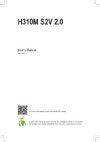
Temperature sensor
l Only for B660M G X AX DDR4.
R_USB20_1
CPU_FAN
SYS_FAN1
ATX
B660M G X AX DDR4
B660M GAMING X DDR4
F_AUDIO
SPDIF_O
AUDIO
BAT
ATX_12V_2X4
CODEC
RST
U32_LAN
PCIEX16
iTE
®
Super I/O
2.5 GbE LAN
LED_C1 F_USB1
SYS_FAN3
SPI_TPM F_PANEL
SATA3
7
6
M2_WIFIl
80
60
60
80
M_BIOS
QFLASH_PLUS
RST_SW
F_U32C
U32_USB20
M2P_SB
M2A_CPU
DDR4_A2
DDR4_A1
DDR4_B1
DDR4_B2
D_LED1
SYS_FAN2
F_USB2
QFLED
DP_HDMI20
COM
USB 2.0 Hub
LGA1700
Intel
®
B660
PCIEX4
THB_C1
THB_C2
SATA3
4 5
USB 2.0 Hub
D_LED2
LED_C2
F_U32
R_USB20_2
110
CLR_CMOS
Содержание
- B660m gaming x ddr4 p.1
- B660m gaming x ax ddr4 p.1
- B660m gaming x ax b660m gaming x b660m g x ax ddr4 p.1
- User s manual p.1
- Rev 1101 p.1
- Identifying your motherboard revision p.2
- Disclaimer p.2
- Copyright p.2
- Chapter 2 hardware installation p.3
- Chapter 3 bios setup 1 p.3
- Chapter 4 installing the operating system and drivers 3 p.3
- Chapter 1 product introduction p.3
- Table of contents p.3
- Chapter 5 appendix 5 p.3
- B660m gaming x p.4
- 1 motherboard layout p.4
- J only for b660m gaming x ax p.4
- Chapter 1 product introduction p.4
- B660m gaming x ax p.4
- B660m gaming x ddr4 p.5
- L only for b660m g x ax ddr4 p.5
- B660m g x ax ddr4 p.5
- 2 box contents p.6
- 1 installation precautions p.7
- Chapter 2 hardware installation p.7
- 2 product specifications p.8
- 2 productspecifications p.8
- A note the cpu orientation p.12
- 3 installing the cpu and cpu cooler p.12
- Follow the steps below to correctly install the cpu into the motherboard cpu socket p.13
- Do not force to engage the cpu socket locking lever when the cpu is not installed correctly as this would damage the cpu and cpu socket p.13
- B installing the cpu p.13
- C installing the cpu cooler p.14
- Be sure to install the cpu cooler after installing the cpu actual installation process may differ depending the cpu cooler to be used refer to the user s manual for your cpu cooler p.14
- 4 installing the memory p.15
- Dualchannelmemoryconfiguration p.15
- 5 installing an expansion card p.16
- 6 back panel connectors p.17
- Usb 2 1 port p.17
- Hdmi 2 port p.17
- Displayport p.17
- Usb 3 gen 1 port p.17
- Usb 2 1 port q flash plus port p.17
- Sma antenna connectors 2t2r jl p.17
- Audio jack configurations p.18
- Rj 45 lan port p.18
- Please visit gigabyte s website for details on configuring the audio software p.18
- Playback device to change the default setting first p.18
- Optical s pdif out connector p.18
- Mic in rear speaker out a a a p.18
- Mic in rear speaker out p.18
- Line out front speaker out a a a a p.18
- Line out front speaker out p.18
- Your device and then remove it from the motherboard p.18
- Jack headphone 2 channel 4 channel 5 channel 7 channel p.18
- You can change the functionality of an audio jack using the audio software to configure 7 channel audio you need to open the audio software and select device p.18
- Front panel mic in center subwoofer speaker out a a p.18
- When removing the cable pull it straight out from the connector do not rock it side to side p.18
- When removing the cable connected to a back panel connector first remove the cable from p.18
- Front panel line out side speaker out a p.18
- To prevent an electrical short inside the cable connector p.18
- This connector provides digital audio out to an external audio system that supports digital optical audio before using this feature ensure that your audio system provides an optical digital audio in connector p.18
- The mic in jack p.18
- The line out jack p.18
- The gigabit ethernet lan port provides internet connection at up to 2 gbps data rate the following describes the states of the lan port leds p.18
- 7 internal connectors p.19
- With the use of the power connector the power supply can supply enough stable power to all the components on the motherboard before connecting the power connector first make sure the power supply is turned off and all devices are properly installed the power connector possesses a foolproof design connect the power supply cable to the power connector in the correct orientation p.20
- To meet expansion requirements it is recommended that a power supply that can withstand high power consumption be used 500w or greater if a power supply is used that does not provide the required power the result can lead to an unstable or unbootable system p.20
- The 12v power connector mainly supplies power to the cpu if the 12v power connector is not connected the 12v power connector mainly supplies power to the cpu if the 12v power connector is not connected the computer will not start p.20
- 2 atx_12v_2x4 atx 2x4 12v power connectors and 2x12 main power connector p.20
- 4 cpu_fan sys_fan1 2 3 fan headers p.21
- Led_c1 led_c2 rgb led strip headers p.21
- All fan headers on this motherboard are 4 pin most fan headers possess a foolproof insertion design when connecting a fan cable be sure to connect it in the correct orientation the black connector wire is the ground wire the speed control function requires the use of a fan with fan speed control design for optimum heat dissipation it is recommended that a system fan be installed inside the chassis p.21
- These fan headers are not configuration jumper blocks do not place a jumper cap on the headers p.21
- The headers can be used to connect a standard 5050 rgb led strip 12v g r b with maximum power rating of 2a 12v and maximum length of 2m p.21
- Overheating overheating may result in damage to the cpu or the system may hang p.21
- For how to turn on off the lights of the led strip please navigate to the unique features page of gigabyte s website p.21
- Connect your rgb led strip to the header the power pin marked with a triangle on the plug of the led strip must be connected to pin 1 12v of this header incorrect connection may lead to the damage of the led strip p.21
- Before installing the devices be sure to turn off the devices and your computer unplug the power cord from the power outlet to prevent damage to the devices p.21
- Be sure to connect fan cables to the fan headers to prevent your cpu and system from p.21
- Sata3 4 5 6 7 sata 6gb s connectors p.22
- Pin no definition p.22
- No pin p.22
- For how to turn on off the lights of the led strip please navigate to the unique features page of gigabyte s website p.22
- D_led1 d_led2 addressable led strip headers p.22
- Connect your addressable led strip to the header the power pin marked with a triangle on the plug of the led strip must be connected to pin 1 of the addressable led strip header incorrect connection may lead to the damage of the led strip p.22
- Chipset supports raid 0 raid 1 raid 5 and raid 10 please navigate to the configuring a raid set page of gigabyte s website for instructions on configuring a raid array p.22
- Before installing the devices be sure to turn off the devices and your computer unplug the power cord from the power outlet to prevent damage to the devices p.22
- To enable hot plugging for the sata ports please navigate to the bios setup page of gigabyte s website and search for sata configuration for more information p.22
- The sata connectors conform to sata 6gb s standard and are compatible with sata 3gb s and sata 1 gb s standard each sata connector supports a single sata device the inte p.22
- The headers can be used to connect a standard 5050 addressable led strip with maximum power rating of 5a 5v and maximum number of 1000 leds p.22
- M2p_sb a a p.23
- M2a_cpu a a p.23
- Follow the steps below to correctly install an m ssd in the m connector step 1 locate the m connector where you will install the m ssd use a screwdriver to unfasten the screw on the heatsink and then remove the heatsink only the m2a_cpu connector has the heatsink step 2 locate the proper mounting hole based on the length of your m ssd drive if needed move the standoff to the desired mounting hole insert the m ssd into the m connector at an angle step 3 press the m ssd down and then use the included screw to secure it in the connector remove the protective film from the bottom of the heatsink then replace the heatsink and secure it to the original hole p.23
- Types of m ssds supported by each m connector p.23
- The m connectors on the motherboard support only m pcie ssds p.23
- M2a_cpu m2p_sb m socket 3 connectors p.23
- M pcie x4 ssd m pcie x2 ssd m sata ssd p.23
- F_panel front panel header p.24
- Pin no definition pin no definition p.25
- Tx1 12 tx2 p.25
- Head phone detection p.25
- The header conforms to usb 3 gen 2 specification and can provide one usb port p.25
- Gnd 14 gnd p.25
- The front panel audio header supports high definition audio hd you may connect your chassis front panel audio module to this header make sure the wire assignments of the module connector match the pin assignments of the motherboard header incorrect connection between the module connector and the motherboard header will make the device unable to work or even damage it p.25
- F_u32c usb type p.25
- Some chassis provide a front panel audio module that has separated connectors on each wire instead of a single plug for information about connecting the front panel audio module that has different wire assignments please contact the chassis manufacturer p.25
- F_audio front panel audio header p.25
- Sense_send p.25
- Cc1 18 d p.25
- Sbu2 20 cc2 p.25
- Sbu1 19 d p.25
- Rx1 16 rx2 p.25
- Rx1 15 rx2 p.25
- Pin no definition p.25
- No pin p.25
- Mic detection p.25
- Vbus 17 gnd p.25
- Header with usb 3 gen 2 support p.25
- Vbus 11 vbus p.25
- Head phone r p.25
- Tx1 13 tx2 p.25
- Head phone l p.25
- Power 5v p.26
- Pin no definition pin no definition p.26
- Pin no definition p.26
- No pin p.26
- Nc 20 no pin p.26
- Gnd 17 ssrx2 p.26
- Gnd 14 sstx2 p.26
- Vbus 11 d2 p.26
- From the power outlet to prevent damage to the usb bracket p.26
- Usb dy p.26
- F_usb1 f_usb2 usb 2 1 headers p.26
- Usb dx p.26
- F_u32 usb 3 gen 1 header p.26
- The headers conform to usb 2 1 specification each usb header can provide two usb ports via an optional usb bracket for purchasing the optional usb bracket please contact the local dealer p.26
- Do not plug the ieee 1394 bracket 2x5 pin cable into the usb 2 1 header prior to installing the usb bracket be sure to turn off your computer and unplug the power cord p.26
- The header conforms to usb 3 gen 1 and usb 2 specification and can provide two usb ports for purchasing the optional 3 front panel that provides two usb 3 gen 1 ports please contact the local dealer p.26
- D1 19 vbus p.26
- Sstx1 16 gnd p.26
- D1 18 ssrx2 p.26
- Sstx1 15 sstx2 p.26
- Ssrx1 13 gnd p.26
- Ssrx1 12 d2 p.26
- Power 3 v p.27
- Pin no definition p.27
- No pin p.27
- Data output p.27
- Data input p.27
- Com serial port header p.27
- Chip select p.27
- You may connect an spi tpm trusted platform module to this header p.27
- The com header can provide one serial port via an optional com port cable for purchasing the optional com port cable please contact the local dealer p.27
- Spi_tpm trusted platform module header p.27
- This header supports s pdif digital output which allows you to connect a s pdif digital audio cable to output digital audio from your motherboard to the supported audio devices for information about connecting the digital audio cable carefully read the manual for your audio devices p.28
- The connectors are used to connect to a gigabyte thunderbol p.28
- Thb_c1 thb_c2 thunderbol p.28
- Supports a thunderbol p.28
- Spdifo p.28
- Spdif_o s pdif out header p.28
- Pin no definition p.28
- No pin p.28
- Add in card connectors p.28
- Add in card p.28
- 5vdual p.28
- Clr_cmos clear cmos jumper p.29
- Bat battery p.29
- Rst_sw rst reset button reset jumper p.30
- Qflash_plus q flash plus button p.30
- Chapter 3 bios setup p.31
- Startup screen p.32
- Function keys p.32
- Chapter 4 installing the operating system and drivers p.33
- 1 operating system installation p.33
- 2 drivers installation p.34
- Raid levels p.35
- Chapter 5 appendix p.35
- Before you begin please prepare the following items p.35
- 1 configuringaraidset p.35
- 1 configuring a raid set p.35
- United states of america federal communications commission statement p.36
- Regulatory notices p.36
- Wireless module approvals p.38
- Contact us p.39
- To submit a technical or non technical sales marketing question please link to https esupport gigabyte com p.39
- Gigabyte esupport p.39
Похожие устройства
-
 Gigabyte GA-B250M-Gaming 3 (rev. 1.0)Руководство пользователя
 -
 Gigabyte H510M KИнструкция по установке
 -
 Gigabyte H610M S2H V2 DDR4Инструкция по эксплуатации
 -
Gigabyte H510M S2H V2Инструкция по установке
-
 Gigabyte B365 S1151 MATX B365M HРуководство по эксплуатации
 -
 Gigabyte CELERON J1800 MITX GA-J1800N-D2H V1.3Руководство по эксплуатации
 -
 Gigabyte B450 SAM4 MATX AMD B450M DS3HРуководство по эксплуатации
 -
 Gigabyte B250 S1151 MATX GA-B250-FINTECHРуководство по эксплуатации
 -
 Gigabyte GA-78LMT-USB3 R2Руководство по эксплуатации
 -
 Gigabyte H370M DS3HРуководство по эксплуатации
 -
 Gigabyte H310 S1151 MATX H310M S2V 2.0Руководство по эксплуатации
 -
 Gigabyte H110 S1151 MATX GA-H110M-S2PVРуководство по эксплуатации