
OPTIBELT Optikrik 0 Инструкция онлайн
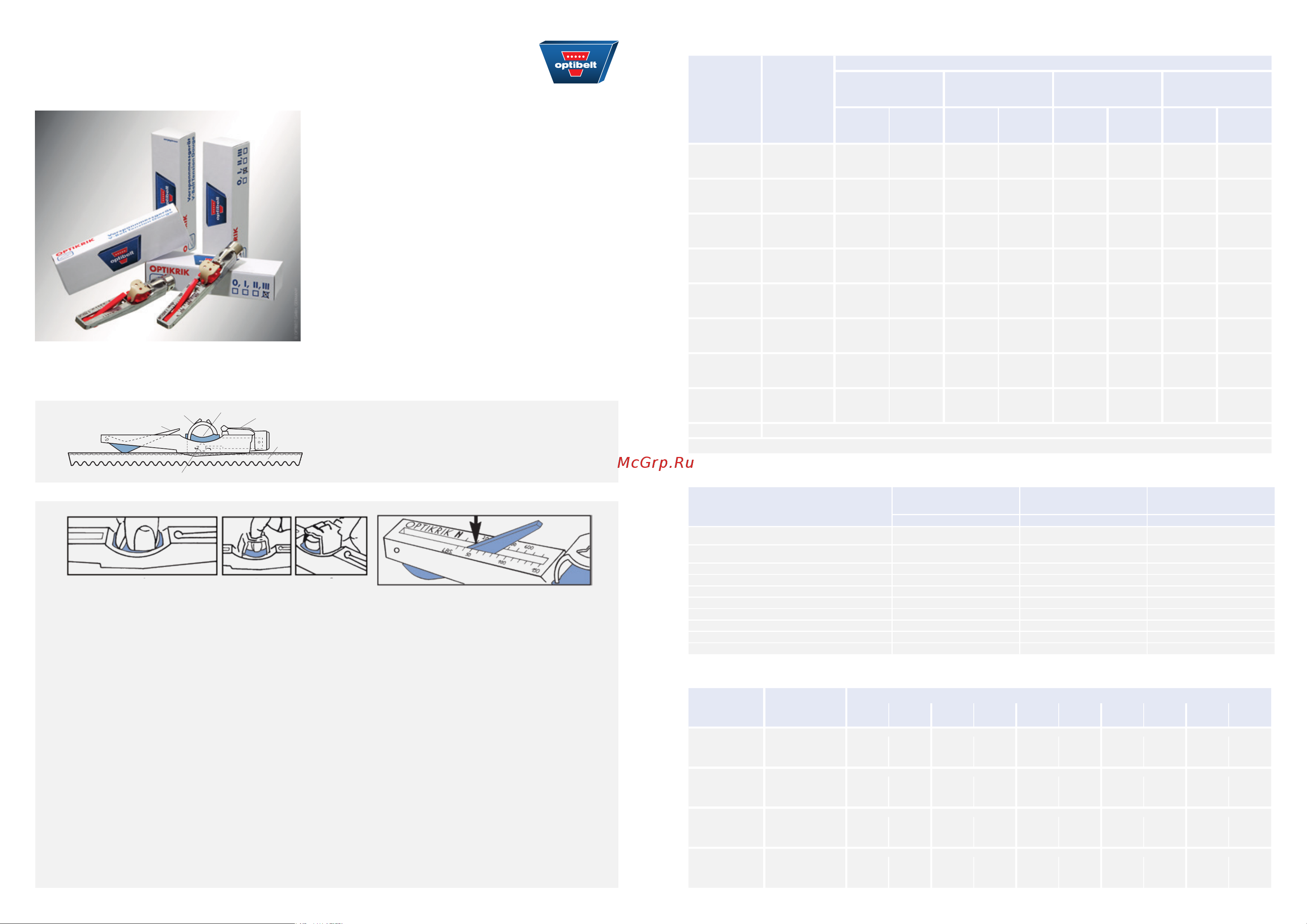
OPTIKRIK
TENSION GAUGES
FOR OPTIBELT V-BELTS AND
RIBBED BELTS
This simplifi ed method for static tension measuring should be
used for installation and maintenance tensioning of the belt
when the important technical data is unavailable and the
optimum tension cannot be calculated. This method requires
only knowledge of the small pulley diameter and the belt
section and construction. The gauges may also be used to set
tensions when the optimum tension has been calculated from
known technical data.
OPTIBELT TENSION GAUGES – INSTRUCTIONS FOR USE –
1. Select the gauge appropriate to the belt section and construction being tensioned. See notes below the simplifi ed
tensioning table.
2. The illustration above (A, B or C) shows three ways to hold the gauge so that pressure is applied to the pad only.
3. Position the gauge on one of the belts on the drive in the middle of an accessible span length. Take care to ensure that
the gauge is only in contact with one of the belts, and that the indicator arm is pushed down into the gauge body.
Align the gauge so that its body is parallel with the sides of the belt.
4. Push down on the pressure pad slowly and fi rmly with one fi nger in one of the ways illustrated above (A, B or C).
When a “click” is heard and / or felt, stop immediately and remove the gauge carefully to avoid disturbing the indicator
arm.
5. Read the gauge to judge the tension as follows and as illustrated in the sketch above.
6. Turn the gauge sideways to ascertain the exact point where the top surface of the indicator arm crosses the scale.
7. Mark this point mentally or with a thumbnail and turn the gauge to read the scale.
8. Check the tension found against the simplifi ed tensioning table or the calculated tension.
Tighten or slacken the belt, if necessary.
Tension Gauges:
OPTIKRIK 0 range: 70 - 150 N
OPTIKRIK I range: 150 - 600 N
OPTIKRIK II range: 500 - 1400 N
OPTIKRIK III range: 1300 - 3100 N
rubber fi nger loop
pocket clip
pressure pad
V-belt
indicator arm
pressure spring
A B C
© OPTIBELT GMBH, GERMANY
TENSION VALUES – AUTOMOTIVE INDUSTRY
Belt
section
Initial installation
Tension
after 30-120 min.
running in
Minimum tension
Static tension [N] Static tension [N] Static tension [N]
AVX 10
MARATHON X, MARATHON 2
550 ± 50 350 ± 50 ≥ 200
AVX 13
MARATHON X, MARATHON 2
650 ± 50 400 ± 50 ≥ 300
KB - 2 AVX 10 1100 ± 50 700 ± 50 ≥ 400
KB - 3 AVX 10 1650 ± 50 1050 ± 50 ≥ 600
KB - 2 AVX 13 1300 ± 50 800 ± 50 ≥ 600
KB - 3 AVX 13 1950 ± 50 1200 ± 50 ≥ 900
RB - 3 PK 400 ± 50 250 ± 50 ≥ 200
RB - 4 PK 500 ± 50 350 ± 50 ≥ 250
RB - 5 PK 600 ± 50 400 ± 50 ≥ 300
RB - 6 PK 750 ± 50 500 ± 50 ≥ 350
TENSION VALUES – INDUSTRIAL RIBBED BELTS
Belt
section
Diameter
of the
small pulley d
b
[mm]
Static tension T
max
[N]
Initial
installation
Operating
after
running in
Initial
installation
Operating
after
running in
Initial
installation
Operating
after
running in
Initial
installation
Operating
after
running in
Initial
installation
Operating
after
running in
PH
4 PH 8 PH 12 PH 16 PH 20 PH
≤ 25
> 25 ≤ 71
> 71 *
90
110
70
90
150
200
130
150
250
300
200
250
300
350
250
300
400
450
300
350
4 PJ 8 PJ 12 PJ 16 PJ 24 PJ
PJ
≤ 40
> 40 ≤ 80
> 80 ≤ 132
> 132 *
200
200
250
150
150
200
350
400
450
300
350
350
500
600
700
400
500
550
700
800
900
550
650
700
1000
1200
1300
800
1000
1000
4 PK 8 PK 10 PK 12 PK 16 PK
PK
≤ 63
> 63 ≤ 100
> 100 ≤ 140
> 140 *
300
400
450
250
300
350
600
800
900
450
600
700
700
1000
1100
600
700
800
900
1200
1300
700
900
1000
1200
1500
1600
900
1200
1300
6 PL 8 PL 10 PL 12 PL 16 PL
PL
≤ 90
> 90 ≤ 140
> 140 ≤ 200
> 200 *
800
1000
1100
600
700
800
1000
1300
1400
800
1000
1100
1300
1600
1900
1000
1300
1400
1500
1900
2100
1200
1500
1600
1900
2500
2800
1500
1900
2100
TENSION VALUES – INDUSTRIAL V-BELTS
Belt
section
Diameter
of the small
pulley
[mm]
Static belt tension [N]
Standard
(wrapped)
SUPER X-POWER M=S
SUPER TX M=S
SUPER XE-POWER PRO
RED POWER 3
Initial
installation
Operating after
running in
Initial
installation
Operating after
running in
Initial
installation
Operating after
running in
Initial
installation
Operating after
running in
SPZ;
3V/9N;
XPZ;
3VX/9NX
≤ 71
> 71 ≤ 90
> 90 ≤ 125
> 125*
200
250
350
150
200
250
250
300
400
200
250
300
300
350
500
250
300
400
250
300
400
200
250
300
SPA;
XPA
≤ 100
> 100 ≤ 140
> 140 ≤ 200
> 200*
350
400
500
250
300
400
400
500
600
300
400
450
500
600
700
400
500
550
400
500
600
300
400
450
SPB;
5V/15N;
XPB;
5VX/15NX
≤ 160
> 160 ≤ 224
> 224 ≤ 355
> 355*
650
700
900
500
550
700
700
850
1000
550
650
800
850
1000
1200
650
800
950
700
850
1000
550
650
800
SPC;
XPC
≤ 250
> 250 ≤ 355
> 355 ≤ 560
> 560*
1000
1400
1800
800
1100
1400
1400
1600
1900
1100
1200
1500
1700
1900
2300
1300
1550
1800
1400
1600
1900
1100
1200
1500
Z/10;
ZX/X10
≤ 50
> 50 ≤ 71
> 71 ≤ 100
> 100*
90
120
140
70
90
110
120
140
160
90
110
130
— — — —
A/13;
AX/X13
≤ 80
> 80 ≤ 100
> 100 ≤ 132
> 132*
150
200
300
110
150
250
200
250
400
150
200
300
— — — —
B/17;
BX/X17
≤ 125
> 125 ≤ 160
> 160 ≤ 200
> 200*
300
400
500
250
300
400
450
500
600
350
400
450
— — — —
C/22;
CX/X22
≤ 200
> 200 ≤ 250
> 250 ≤ 355
> 355*
700
800
900
500
600
700
800
900
1000
600
700
800
— — — —
8V Check of the belt tension with help of the length addition value
* Tension values for these pulleys and belt types must be calculated, please consult Optibelt.
© OPTIBELT GMBH, GERMANY
BEDIENUNGSANLEITUNG/OPTIKRIK/GB/1020
Похожие устройства
- Lammin PREMIUM AL500-80-8 LM11108080008 Технический паспорт
- OPTIBELT Optikrik I Инструкция
- OPTIBELT Optikrik II Инструкция
- OPTIBELT Optikrik III Инструкция
- Norgau 042035030 Инструкция к NORGAU 042035030
- ЧИЗ стальная, 150 мм, ГОСТ с поверкой 212034а Описание типа СИ
- ЧИЗ стальная, 300 мм, ГОСТ с поверкой 212039а Описание типа СИ
- Элитест ЛИ-3-10× 00115311 Инструкция по эксплуатации
- АЛЬФА-НДТ ЛИ-3-10x, с первичной калибровкой УП-00003714 Лупа ЛИ-3-10х Паспорт
- Gigant GW1025 Рекомендательные письма
- Inforce COMPACT 06-11-27 Рекомендательные письма
- Gigant GW525 Рекомендательные письма
- Gigant GMT 1025 10x25 мм с магнитным захватом Рекомендательные письма
- Gigant GMT 316 3x16 мм с магнитным захватом Рекомендательные письма
- Gigant GMT 319 3x19 мм с магнитным захватом Рекомендательные письма
- Gigant GMT 519 5x19 мм с магнитным захватом Рекомендательные письма
- Gigant GMT 525 5x25 мм с магнитным захватом Рекомендательные письма
- Inforce 10х25мм 06-11-04 Рекомендательные письма
- Pedrollo 4ZPC05A1 Инструкция по эксплуатации
- RGK rl3 с поверкой 756006 Инструкция по поиску сведений в ФГИС "Аршин"