![Asus PRIME A320M-K — подключение системных панелей и портов на материнской плате [11/28]](/img/pdf.png)
Asus PRIME A320M-K — подключение системных панелей и портов на материнской плате [11/28]
![Asus PRIME A320M-K Руководство пользователя онлайн [11/28] 195141](/views2/1233063/page11/bgb.png)
ASUS PRIME A320M-K
1-3
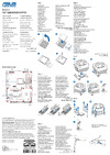
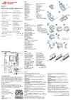
System panel connector (10-1 pin F_PANEL)
Thisconnectorsupportsseveralchassis-mountedfunctions.
Speaker connector (4-pin SPEAKER)
This4-pinconnectorisforthechassis-mountedsystemwarningspeaker.The
speakerallowsyoutohearsystembeepsandwarnings.
USB 3.1 Gen 1 connector (20-1 pin USB3_12)
ThisconnectorallowsyoutoconnectaUSB3.1Gen1moduleforadditionalUSB
3.1Gen1frontorrearpanelports.WithaninstalledUSB3.1Gen1module,you
canenjoyallthebenetsofUSB3.1Gen1includingfasterdatatransferspeeds
ofupto5Gbps,fasterchargingtimeforUSB-chargeabledevices,optimizedpower
efciencyandbackwardcompatibilitywithUSB2.0.
USB 2.0 connectors (10-1 pin USB34, USB56)
TheseconnectorsareforUSB2.0ports.ConnecttheUSBmodulecabletoany
oftheseconnectors,theninstallthemoduletoaslotopeningatthebackofthe
systemchassis.TheseUSBconnectorscomplywithUSB2.0specicationsand
supportupto480Mbpsconnectionspeed.
Neverconnecta1394cabletotheUSBconnectors.Doingsowilldamagethe
motherboard!
Clear RTC RAM (2-pin CLRTC)
ThisheaderallowsyoutocleartheCMOSRTCRAMdataof
thesystemsetupinformationsuchasdate,time,andsystem
passwords.
To erase the RTC RAM:
1. TurnOFFthecomputerandunplugthepowercord.
2. Useametalobjectsuchasascrewdrivertoshortthe
twopins.
3. PlugthepowercordandturnONthecomputer.
4. Holddownthe<Del>keyduringthebootprocessand
enterBIOSsetuptore-enterdata.
CLRTC
+3V_BAT
GND
PIN 1
Ifthestepsabovedonothelp,removetheonboardbatteryandshortthetwopinsagain
tocleartheCMOSRTCRAMdata.AfterclearingtheCMOS,reinstallthebattery.
Serial port connector (10-1 pin COM)
Thisconnectorisforaserial(COM)port.Connecttheserialportmodulecableto
thisconnector,theninstallthemoduletoaslotopeningatthebackofthesystem
chassis.
AMD A320 Serial ATA 6.0Gb/s connectors (7-pin SATA6G_1~4)
TheseconnectorsconnecttoSerialATA6.0Gb/sharddiskdrivesviaSerialATA
6.0Gb/ssignalcables.
Содержание
- Advanced mode p.1
- Bios information p.1
- Motherboard overview p.1
- Bios setup program p.1
- Asus contact information p.1
- Appendix p.1
- System memory p.1
- Notices p.1
- Central processing unit cpu p.1
- Product introduction p.1
- Ez mode p.1
- Exit menu p.1
- E12854 revised edition april 2017 p.2
- Chapter 1 product introduction p.3
- Contents p.3
- Chapter 2 bios information p.3
- Appendix p.3
- Safety information p.4
- Electrical safety p.4
- Operation safety p.4
- How this guide is organized p.4
- About this guide p.4
- Where to find more information p.5
- Typography p.5
- Conventions used in this guide p.5
- Prime a320m k specifications summary p.6
- Package contents p.6
- Check your motherboard package for the following items p.6
- Easy pc diy p.7
- Quiet thermal design p.7
- Prime a320m k specifications summary p.7
- Dependable stability p.7
- Superb performance p.7
- Prime a320m k specifications summary p.8
- Motherboard overview p.9
- Asus prime a320m k p.9
- Product introduction p.9
- Cpu and chassis fan connectors 4 pin cpu_fan 4 pin cha_fan p.10
- Connectthefancablestothefanconnectorsonthemotherboard ensuringthat theblackwireofeachcablematchesthegroundpinoftheconnector p.10
- M socket 3 p.10
- Atx power connectors 24 pin eatxpwr 4 pin atx12v p.10
- Amd am4 cpu socket p.10
- Thissocketallowsyoutoinstallm ngff ssd modules p.10
- Thismotherboardcomeswithanamdam4socketdesignedforamd ryzen 7thgenerationa series athlon processors p.10
- Theseconnectorsareforatxpowersupplyplugs thepowersupplyplugsare designedtofittheseconnectorsinonlyoneorientation findtheproperorientation andpushdownfirmlyuntiltheconnectorscompletelyfit p.10
- Install2gb 4gb 8gb and16gbunbufferedeccandnon eccddr4dimms intothesedimmsockets p.10
- Ddr4 dimm slots p.10
- Chapter 1 product introduction p.10
- Front panel audio connector 10 1 pin aafp p.12
- Chapter 1 product introduction p.12
- A b c d e f g h p.12
- Thismotherboardsupportsonepciexpress3 2 x16graphiccardthat complieswiththepciexpressspecifications p.12
- Thismotherboardhastwopciexpress2 x1slotsthatsupportpciexpressx1 networkcards scsicards andothercardsthatcomplywiththepciexpress specifications p.12
- Thisconnectorisforanadditionalsony philips digitalinterface s pdif port connectthes pdifoutmodulecabletothisconnector then installthemoduletoaslotopeningatthebackof thesystemchassis p.12
- Thisconnectorisforachassis mountedfrontpanelaudioi omodulethatsupports eitherhdaudioorlegacyac 97audiostandard connectoneendofthefront panelaudioi omodulecabletothisconnector p.12
- Pci express 3 2 x16 slot p.12
- Pci express 2 x1 slots p.12
- Irq assignments for this motherboard p.12
- Foramdam4a series athlon seriesprocessors p.12
- Digital audio connector 4 1 pin spdif_out p.12
- Processors p.13
- Asus prime a320m k p.13
- A b c d e f g h p.13
- Forryze p.13
- Rear panel connectors p.14
- Asus prime a320m k p.15
- Ps 2 keyboard purple port thisportisforaps 2keyboard p.15
- Microphone port pink thisportconnectstoamicrophone p.15
- Line out port lime thisportconnectstoaheadphoneoraspeaker inthe4 5 and7 channelconfigurations thefunctionofthisportbecomesfrontspeaker out p.15
- Line in port light blue thisportconnectstothetape cd dvdplayer orother audiosources p.15
- Hdmi port thisportisforahigh definitionmultimediainterface hdmi connector andishdcpcompliantallowingplaybackofhddvd blu ray andotherprotected content p.15
- Audio2 4 5 or7 channelconfiguration p.15
- Central processing unit cpu p.16
- Themotherboardcomeswithanamdam4socketdesignedforamd ryzen 7thgenerationa series athlon processors p.16
- Installing the cpu p.16
- Chapter 1 product introduction p.16
- Asus prime a320m k p.17
- Thismotherboardcomeswithtwodoubledatarate4 ddr4 dualinlinememorymodule dimm sockets thefigureillustratesthelocationoftheddr4dimmsockets p.17
- System memory p.17
- Recommendedmemoryconfiguration p.17
- Overview p.17
- Channel sockets p.17
- To remove a dimm p.18
- Installing a dimm p.18
- Chapter 1 product introduction p.18
- Entering bios setup at startup p.19
- Entering bios setup after post p.19
- Bios setup program p.19
- Bios menu screen p.19
- Bios information p.19
- Ez mode p.20
- Theadvancedmodeprovidesadvancedoptionsforexperiencedend userstoconfigurethe biossettings thefigurebelowshowsanexampleofthe advanced mode refertothe followingsectionsforthedetailedconfigurations p.21
- Advanced mode p.21
- Save changes reset p.22
- Load optimized defaults p.22
- Launch efi shell from usb drives p.22
- Exit menu p.22
- Discard changes and exit p.22
- Search on faq p.22
- Notices p.23
- Federal communications commission statement p.23
- Appendix p.23
- Vcci japan compliance statement p.24
- Kc korea warning statement p.24
- Ic canadian compliance statement p.24
- Déclaration de conformité d industrie canada p.24
- Class b ite p.24
- Canadian department of communications statement p.24
- Regional notice for california p.25
- Google license terms p.25
- Asus recycling takeback services p.25
- Appendix p.26
- Asus computer international america p.27
- Asus computer gmbh germany and austria p.27
- Technical support p.27
- Asustek computer inc p.27
- Asus contact information p.27
- Asus computer international p.28
- Declaration of conformity p.28
- Ca 94539 p.28
Похожие устройства
-
 Asus TUF GAMING B550-PROРуководство по быстрому запуску
 -
 Asus PRIME A520M-A IIКраткое руководство пользователя
 -
 Asus PRIME B250M-PLUSКраткое руководство
 -
 Asus TUF GAMING Z590-PLUSКраткое руководство
 -
 Asus ProArt B650-CREATORКраткий обзор функций
 -
 Asus TUF GAMING B650-PLUSБыстрый старт
 -
 Asus ROG STRIX X670E-I GAMING WIFIКраткое руководство пользователя
 -
Asus ROG FPS-IIРуководство по быстрому запуску
-
 Asus Pro WS W680M-ACE SEКраткая эксплуатационная инструкция
 -
 Asus PRIME B760M-A WIFI D4Инструкция в сокращённом виде
 -
 Asus PRIME H770-PLUSБыстрый старт
 -
 Asus B850-PLUS WIFIКраткое руководство
Узнайте, как правильно подключить системные панели, USB и SATA порты на материнской плате. Подробные инструкции и советы по настройке.