
Electrolux ETR/F-1447A НС-1083760 Инструкция к товару онлайн
c
an be up to approx. 50 m in length. Sensor
cables must be installed in accordance with
current regulations. They must never be
i
nstalled parallel to power cables as electrical
i
nterference may distort the sensor signal.
T
hermostat installation
T
he thermostat should be DIN-rail mounted in
a
n approved panel.
Connect supply voltage to terminals 1 and 2.
E
lectrical installation must be performed in
a
ccordance with applicable local regulations.
Setup
E
TR2 can be set up for ice and snow melting on
o
utdoor areas in conjunction with ETOG
sensors or in gutters/downpipes in conjunction
with ETOR and ETF sensors.
•
Electric heating control with ETOG
(
fig. 5 + 7):
Connect 1 ETOG sensor to terminals 8-14.
C
onnect heating cable to output relay
a
ccording to fig. 7.
• Electric heating control with ETOR + ETF
(fig. 6 + 7):
C
onnect 1 ETOR sensor to terminals 10-14.
N
ote that the pink and grey wires must not be
connected.
C
onnect 1 ETF sensor to terminals 8 and 9.
Connect heating cable to output relay
according to fig. 7.
WIRING (fig. 3)
Terminal Colour code Wiring
1, 2 Supply voltage,
230 V AC 50/60 Hz
5, 7 Output relay,
16 A (potential free), (fig.7)
8, 9 grey/pink Temperature sensor 1,
(1/2) ETOG or ETF
10, 11 yellow/white Moisture sensor,
(5/6) ETOG or ETOR
13, 14 brown/green Sensor heating
(3/4) ETOG or ETOR
Be aware that the pink and grey wire must not
be installed.
Environment protection and recycling
Help protect the environment by disposing of
the packaging and redundant products in a
responsible manner.
Product disposal
Products marked with this symbol
must not be disposed of along with
household refuse but must be
delivered to a waste collection
centre in accordance with current
local regulations.
Figures
Fig. 1. Installation of embedded sensor
1 Sensor
2 Installation plate
3 Heating element
Fig. 2. Installation of ETOR gutter sensor and
ETF outdoor sensor
1 Thermostat ETR2
2 Gutter sensor
3 Outdoor sensor
OJ ELECTRONICS A/S
Stenager 13B · DK-6400 Sønderborg
Tel.: +45 73 12 13 14 · Fax +45 73 12 13 13
oj@ojelectronics.com · www.ojelectronics.com
5
7653C 02/11 (MBC)
1
b
y qualified electricians. Electrical installation
must be performed in accordance with applica-
ble local regulations.
T
ECHNICAL DATA
Thermostat ETR2-1550:
S
upply voltage . . . . .230 V AC ±10%, 50-60 Hz
O
utput relay (potential-free contact, NO) . .16 A
O
n/off differential . . . . . . . . . . . . . . . . . . . .0.3°C
Temperature Setting for Startup . . . . . .0/+10°C
R
un-on time . . . . . . . . . . . . . . . . . . . . .0-5 hours
A
mbient temperature . . . . . . . . . . . . .-10/+50°C
Ambient air humidity . . . . . . . . . . . . . . .10-95%
Enclosure rating . . . . . . . . . . . . .IP 20 / Nema 1
P
ower consumption . . . . . . . . . . . . . . . . . . .3 VA
W
eight . . . . . . . . . . . . . . . . . . . . . . . . . . .200 g
Dimensions H/W/D . . . . . . . . . . . . 86/52/59 mm
G
round sensor type ETOG-55:
D
esigned to be embedded in outdoor areas.
Detection . . . . . . . . . .Moisture and temperature
M
ounting . . . . . . . . . . . . . . . . . . . .Outdoor area
E
nclosure rating . . . . . . . . . . . . . . . . . . . . .IP 68
Ambient temperature . . . . . . . . . . . . .-50/+70°C
Dimensions . . . . . . . . . . . . . . . . . .H32, Ø60 mm
G
utter sensor type ETOR-55:
Designed to be mounted in gutter or downpipe.
I
s used together with outdoor sensor type ETF.
Detection . . . . . . . . . . . . . . . . . . . . . . . .Moisture
Mounting . . . . . . . . . . . . . . .Gutter or downpipe
Enclosure rating . . . . . . . . . . . . . . . . . . . . .IP 68
Ambient temperature . . . . . . . . . . . . .-50/+70°C
Dimensions H/W/D . . . . . . . . . . .105/30/13 mm
Outdoor sensor type ETF-744/99:
Detection . . . . . . . . . . . . . . . . . . . . .Temperature
Mounting . . . . . . . . . . . . . . . . . . . . . . . . . . .Wall
Ambient temperature . . . . . . . . . . . . .-50/+70°C
Dimensions H/W/D . . . . . . . . . . . .86/45/35 mm
The snow and ice melting system is deactivated
in the event of sensor failure.
SENSOR INSTALLATION
Ground sensor ETOG, fig. 1 + 3:
For installation on outdoor areas where snow
and ice is a regular problem. The sensor must
be embedded with its top flush with the
surroundings with the help of the accompanying
installation plate. The sensor cable must be
installed in accordance with current regulations.
We recommend that cable pipes be laid to
protect the sensor cable. Detailed installation
instructions are supplied with the sensor.
Gutter sensor ETOR, fig. 2 + 4:
For installation in a gutter or downpipe on the
sunny side of the building. It is important to
ensure that the sensor contact elements face
against the flow of melt water. If necessary, two
sensors can be installed in parallel.
Be aware that
the pink and grey wire must not be installed.
Detailed installation instructions are supplied
with the sensor.
Outdoor sensor ETF, fig. 2 + 4:
For use in conjunction with gutter sensor ETOR.
Can also be used separately for the detection of
temperature alone. The sensor should be
mounted on the wall under the eaves on the
north side of the building.
Sensor cables
ETOG and ETOR are supplied with 10 m cable,
which can be extended up to approx. 200 m
using standard installation cable: 6x1.5 mm² for
ETOG and 4x1.5 mm² for ETOR. The ETF cable
• English
• Deutsch
• Français
• Русский
• Polski
• Italiano
English
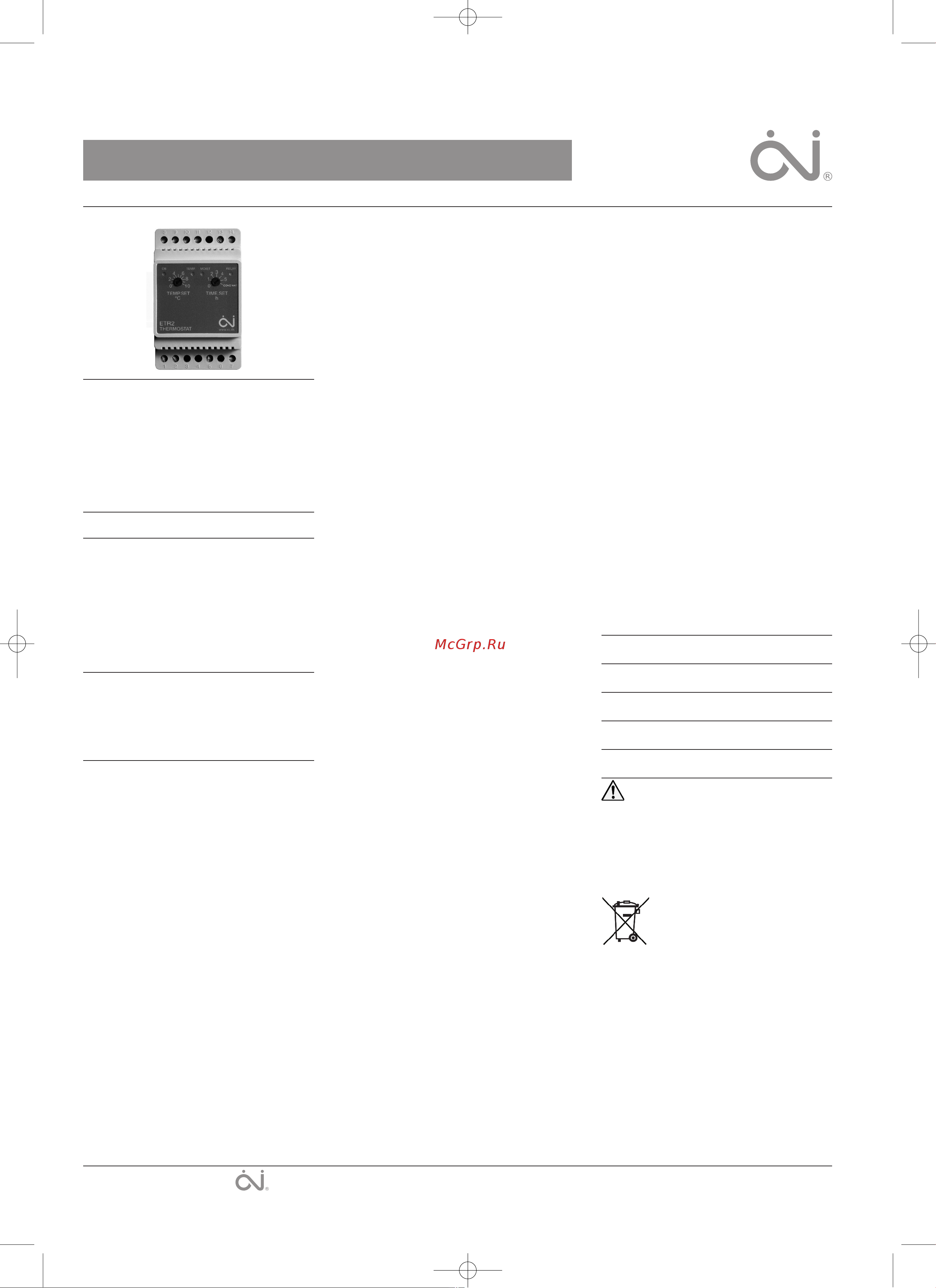
Type ETR2 is an electronic thermostat for
e
conomical ice and snow melting on outdoor
areas and in gutters. Ice forms due to a
combination of low temperature and moisture.
ETR2 detects temperature and moisture and the
snow melting system will usually only be
activated if snow or ice is present. ETR2 is
suitable for controlling electric heating cables.
Product program
ETR2-1550 Thermostat.
ETOG-55 Ground sensor for detecting
temperature and moisture.
ETOR-55 Gutter sensor for detecting moisture.
ETF-744/99 Outdoor sensor for detecting
temperature.
CE MARKING
OJ Electronics A/S hereby declares that the
product is manufactured in accordance with
Council Directive 89/336/EEC on
electromagnetic compatibility (and subsequent
amendments) and Council Directive
2006/95/EEC on electrical equipment designed
for use within certain voltage limits.
Applied standards
EN 61000-6-3, EN 61000-6-2, EN 60730-1 and
EN 60730-2-9.
The product may only be used if the complete
installation complies with current directives.
The product carries a manufacturer's warranty if
installed in accordance with these instructions
and current regulations.
If the product has been damaged in any way,
e.g. during transport, it must be inspected and
checked by authorised personnel before being
connected to the power supply.
WARNING – Important safety instructions.
Always disconnect the power supply before
performing installation or maintenance work on
this control unit or any of the components con-
nected to it. This control unit and the compo-
nents connected to it should only be installed
INSTRUCTIONS
OJ Microline
®
Type ETR2
The OJ trademark is a registred trademark belonging to OJ Electronics A/S · © 2011 OJ Electronics A/S
57653C-02-11.qxd:skabelon-A4 04/03/11 14:00 Side 1
Похожие устройства
- Теплолюкс EcoSmart 25 2239190 Руководство по эксплуатации
- Теплолюкс LumiSmart 25 2239191 Руководство по эксплуатации
- HEATLINE HLT-D-504 Инструкция к HEATLINE HLT-D-504
- Sibling 00-00017045 Руководство по эксплуатации
- Sibling 00-00017044 Руководство по эксплуатации
- EASTEC (На DIN рейку. 3,5 кВт) E-32 DIN Инструкция по монтажу и эксплуатации
- Electrolux ETA-16 НС-1017322 Инструкция по эксплуатации
- Electrolux ETA-16 НС-1017322 Инструкция по эксплуатации
- Electrolux ETA-16 НС-1017322 Инструкция по эксплуатации
- Electrolux ETA-16 НС-1017322 Инструкция по эксплуатации
- Electrolux ETB-16 НС-1013675 Инструкция по эксплуатации
- Electrolux ETB-16 НС-1013675 Инструкция по эксплуатации
- Electrolux ETB-16 НС-1013675 Инструкция по эксплуатации
- Electrolux ETB-16 НС-1013675 Инструкция по эксплуатации
- Electrolux ETL-16W НС-1432041 Инструкция
- Electrolux ETS-16W НС-1432045 Инструкция
- Electrolux ETT-16 НС-1017321 Инструкция по эксплуатации
- Electrolux ETT-16 НС-1017321 Инструкция по эксплуатации
- Electrolux ETT-16 НС-1017321 Инструкция по эксплуатации
- Electrolux ETT-16 НС-1017321 Инструкция по эксплуатации