![FAR 220 В, 1/2", НР-ВР, 8 сек FA 300717 1208 Инструкция к FAR FA 300717 1208 онлайн [2/2] 861657](/img/pdf.png)
FAR 220 В, 1/2", НР-ВР, 8 сек FA 300717 1208 Инструкция к FAR FA 300717 1208 онлайн [2/2] 861657
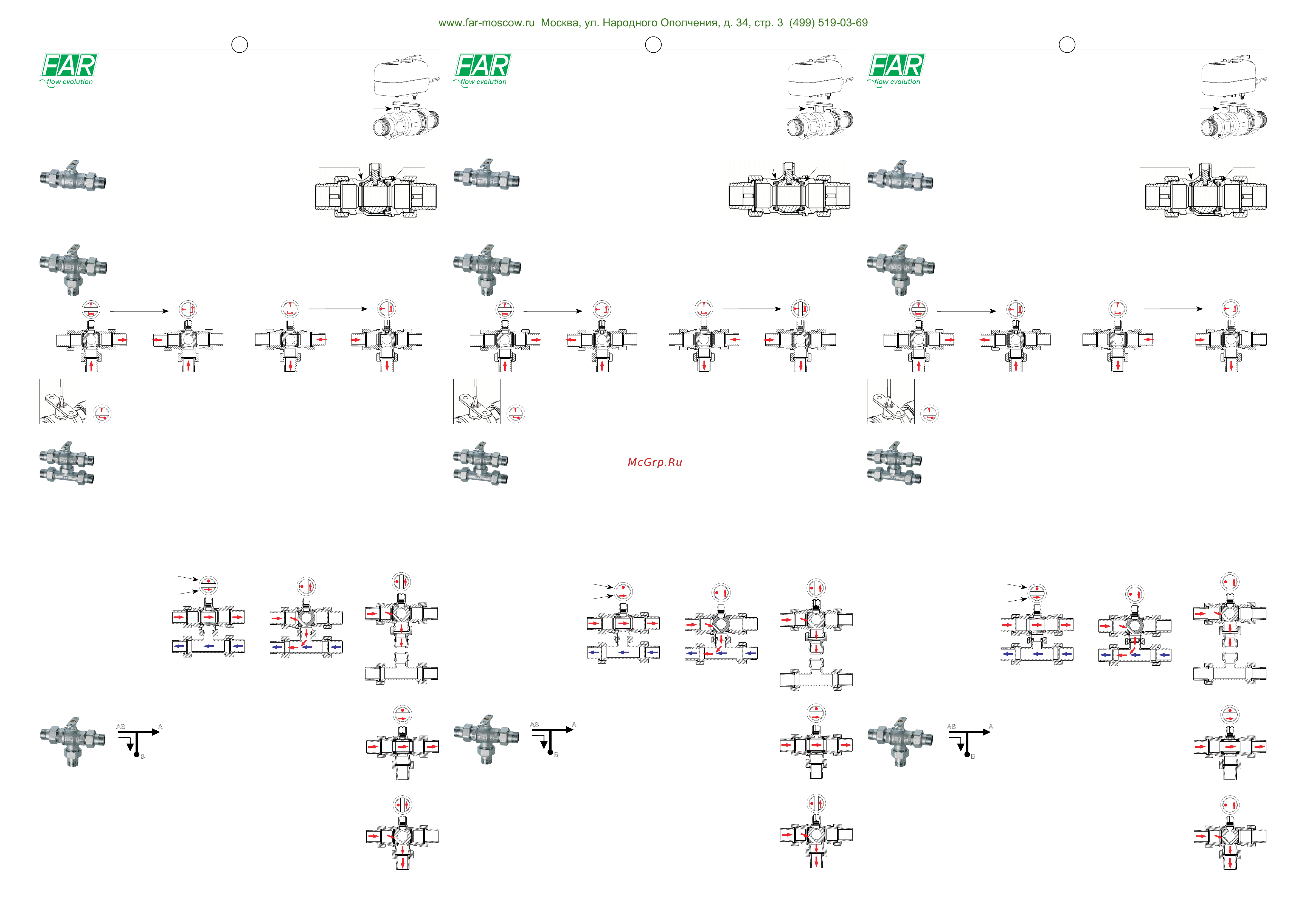
ART.3032 3-WAY ZONE VALVE WITH BY-PASS
AB A
B
TECHNICAL FEATURES
seats in p.t.f.e. O-Ring
Open valve
ART.3015-3016-3017 2-WAY ZONE VALVE
The actuator must be installed with the valve totally opened and actuators are supplied
in “open” condition. “SMALL” actuators are compatible with all FAR zone valves.
ACTUATORS
“SMALL” ACTUATOR
NUTS (SUPPLIED
WITH ACTUATOR)
FAR Rubinetterie S.p.A. - www.far.eu
Instructions
Opening times:
40s
Art.3001 230V
Art.3002 24 V
Opening times:
40s
Art.3005 230V
Art.3006 24V
Opening times:
8s
Art.3007 230V
Art.3008 24V
3-Way zone valve with “L” passage is a diverter valve with uid inlet from below and uid delivery to
the thermal carrier towards right or left as a function of the position of actuator (Pic.1); or entering from
right or left and diverted towards the centre (Pic.2).
This valve is ideal for the commutation of the system, depending on the change of seasons.
ART.3020-3021-3022 3-WAY DIVERTER ZONE VALVE
Pic.1
90° Rotation
Pic.2
90° Rotation
The illustration shows how the position of the ball permits the inlet of uid from below and then diverts it
to the right. In the same position it can permit uid to enter from the right and then divert it downwards.
Before installing the actuator, it is essential to check that the ow aperture in the ball of the valve is positioned
in the desired direction. The valve can be adjusted by means of a screwdriver. The silk-screen printing on the
control stem shows the position of the ball.
Open valve
Full passage
Closed valve
Passage through by-pass
The zone valve features a special anti-blockage system inside,
which prevents the valve blocking in even the worst operating
conditions. The system comprises two PTFE seats located on
two O-rings, which operate as “shock absorber” so that ball
GB
ZONE VALVES
INSTRUCTIONS FOR INSTALLATION
: UNI EN 12165:98 CW617N Brass
: Anti-blockage system with OR in EPDM and seats in PTFE
: UNI EN 12164:98 CW614N Brass
: 16 bar
: 5 bar
: -10 °C (with antifreeze) +100 °C
: water, water with glycol
Valve body and ball
Sealing gaskets
Control stem
Nominal working pressure
Differential maximum pressure
Circulating uid temperature
Usable uids
The zone valve (Type 3032) is provided with a by-pass
ball like Art.3025, but the connections are three male
unions. Picture A shows the valve in case of full passage,
when the ow is delivered to the system; while picture B
shows the valve in case of by-pass passage, when the
uid thermal carrier is sent back to the boiler.
rotation is guaranteed – even if it has not been used for a long period. All models of
zone valve feature this system. The 2-Way zone valve is also available with female-
female (type art.3016) and male-female (type art.3017) connections.
ART.3025 3-WAY ZONE VALVE WITH BY-PASS TEE
Open valve
Full passage
Position of by-pass bore
Flow direction
Art.3027
Art.3031
Art.3030
Closed valve
Passage through by-pass
IMPORTANT: In case the valve is
assembled with ow delivery through
the by-pass Tee, it is essential to
check that the arrow on the control
stem corresponds to the uid direction.
The 3-Way valve with by-pass (type 3025) is designed for use in the zone pipework, with no need for
differential pressure valves to maintain system design heads.
The interaxis of the by-pass Tee connection increases from 52mm to 63mm compared with the valve body
for easy compatibility with most manifolds on the market – ensuring good ow and return connections in the
zone pipework.
The picture shows the by-pass orice when the valve is closed. In this case the ow is sent back to the boiler, thus maintaining
the design system heads. In this way the pump is not overstressed by high pressure surges, that could wear the pump itself.
N.B: The art.3025 is suitable for use in association with coplanar manifolds. It is advisable this kind of use only.
Fluid can enter whether from the right or from the left, as long as the arrow on the control stem corresponds to the uid direction.
The red point shows by-pass position. It is possible to choose among three options:
Art.3025 with adjustable interaxis from 52 to 63 mm, suitable for use with coplanar manifolds;
Art.3030 consisting of the valve body (art.3031) and the by-pass Tee (art.3027) connectable with copper, plastic or multilayer
pipe depending on the different requirements, in order to get interaxis of different length;
Art.3032 with unions.
Before installing the actuator, check the position of the arrow. The valve without actuator can be adjusted
by means of a screwdriver. Actuators are supplied in “open” condition and uid can enter whether from
the right or from the left, as long as the arrow is positioned in the same direction of the ow.
Das Zonenventil Art. 3032 verfügt über ein Bypassloch
wie das Ventil Art. 3025 aber die Anschlüsse bestehen
aus der AG-Stutzen. In der Abbildung wird die Montage
des Ventils bei Volluss (d.h. die Flüssigkeit wird in die
Anlage geleitet) und bei Bypass-Funktion dargestellt
(d.h. die Flüssigkeit wird wieder in den Kessel geleitet).
ART.3032 -WEGE-ZONENVENTIL MIT BYPASS
AB A
B
ART.3025 3-WEGE-ZONENVENTIL MIT T-BYPASS
Ventil geöffnet
Volluss
Stellung des
Bypasslochs
Richtung der
Flüssigkeit
Art.3027
Art.3031
Art.3030
Ventil geschlossen
Durchuss durch Bypass
Das 3-Wege-Ventil mit Bypass Art. 3025 wurde speziell für Zonenanlagen entwickelt. Es kann somit
vermieden werden, dass für die Einhaltung der vorgegebenen Werte Differenzialdruckventile eingesetzt
werden müssen. Der T-Anschluss als Bypass, dessen Achsenabstand zum Ventilkörper von 52 mm bis 53
mm variieren kann, ist für fast alle marktüblichen Verteiler geeignet und kann auch als Anschluss für die
Vorlauf- und Rücklaueitungen der Zonenanlage sinnvoll eingesetzt werden.
Ventil geöffnet
Volluss
Ventil geschlossen
Durchuss durch Bypass
ZONENVENTILE
MONTAGEANLEITUNG
TECHNISCHE DATEN
: Messing UNI EN 12165:98 CW617N
: Antiblockiervorrichtung mit OR aus EPDM und Sitze aus PTFE
: Messing UNI EN 12164:98 CW614N
: 16 bar
: 5 bar
: -10 °C (mit Frostschutz) +100 °C
: Wasser und Wasser mit Glykol
Ventilgehäuse und Kugel
Dichtung
Einstellbolzen
Betriebs-Nenndruck
Maximaler Differenzialdruck
Flüssigkeitstemperatur
Zugelassene Flüssigkeiten
Sitze aus PTFE O-Ring
Ventil geöffnet
ART.3015-3016-3017 2-WEGE-ZONENVENTIL
Das 3-Wege-Ventil mit L-Anschluss ist ein Ableitventil mit Einlauf auf der unteren Seite und Auslauf
nach links oder nach rechts, abhängig von der Stellung des Stellantriebs (Abb.1), oder umgekehrt von
rechts bzw. links nach unten (Abb.2). Dieses Ventil eignet sich für die Umschaltung vom Sommer- zum
Winterbetrieb und umgekehrt.
ART.3020-3021-3022 3-WEGE-ZONENVENTIL MIT ABLEITFUNKTION
Abb.1
Drehung um 90°
Abb.2
Drehung um 90°
Der Stellantrieb muss bei komplett geöffnetem Ventil installiert werden. Stellantriebe
werden werkseitig in Stellung “geöffnet“ geliefert. Stellantriebe aus der Reihe “SMALL“
können bei allen FAR-Zonenventilen angewendet werden.
ANWENDBARE STELLANTRIEBE
STELLANTRIEB “SMALL”
MUTTER (MIT DEM
STELLANTRIEB
MITGELIEFERT)
FAR Rubinetterie S.p.A. - www.far.eu
Anleitung
D
Drehungszeit: 40s
Art.3001 230V
Art.3002 24 V
Drehungszeit: 40s
Art.3005 230V
Art.3006 24V
Drehungszeit: 8s
Art.3007 230V
Art.3008 24V
Das Zonenventil beinhaltet eine Antiblockiervorrichtung,
die auch unter den schwierigsten Einsatzbedingungen das
Klemmen des Ventils verhindert. Die Antiblockiervorrichtung
besteht aus zwei O-Ringen als Auagen für die Sitze aus PTFE.
In diesem Fall ist an der Anzeige ersichtlich, dass die Kugel den Einlauf der Flüssigkeit von unten nach
rechts ermöglicht. Der Einlauf der Flüssigkeit kann auch von rechts nach unten erfolgen.
Vor der Installation des Servoantriebs, bitte Stellung der Anzeige am Kugelloch prüfen, damit die Stellung
der gewünschten Richtung entspricht. Das Ventil kann durch einen Schraubenzieher geregelt werden. Die
Markierung am Einstellbolzen zeigt die Stellung der Kugel.
WICHTIG: Wird das Ventil so
installiert, dass der Vorlauf durch den
T-Bypass durchläuft, so muss der
Pfeil am Einstellbolzen in der gleicher
Richtung der Flüssigkeit liegen.
Die O-Ringe fungieren als Dämpfer und gewährleisten eine reibungslose Bewegung
der Kugel auch wenn das Ventil lange Zeit nicht betätigt wird. Alle Zonenventile
in jeder Ausführung beinhalten die Antiblockiervorrichtung. Das 2-Wege-Ventil ist
auch in der Ausführung IG-IG als Art. 3016 und AG-IG als Art. 3017 lieferbar.
In der Abbildung ist das Bypassloch bei geschlossenem Ventil dargestellt. In diesem Fall wird die Flüssigkeit wieder in den Kessel
geleitet, um die vorgegebenen Werte einzuhalten. Die Pumpe wird somit nicht durch zu viele Lastenänderungen überlastet. Es
wird eine Ermüdung und eine schnelle Abnutzung der Pumpe vermieden.
N.B.: Der Art. 3025 ist für Kompaktverteiler geeignet. Es wird empfohlen, diesen Artikel nur mit Kompaktverteilern anzuwenden.
Der Einlauf der Flüssigkeit kann von rechts oder von links erfolgen, vorausgesetzt, dass der Pfeil am Einstellbolzen in der
gleichen Richtung der Flüssigkeit liegt. Der rote Punkt zeigt die Stellung des Bypasslochs. Es sind drei Ausführungen möglich:
Art. 3025 mit variablem Achsenabstand von 52 bis 63 mm, für den Einsatz mit Kompaktverteilern.
Art. 3030 bestehend aus Ventilkörper Art. 3031 und T-Bypass Art. 3027, für den Anschluss mit Kupfer, Kunststoff oder
Verbundstoff, je nach Bedarf. Es können somit jede Achsenabstände realisiert werden.
Art. 3032 mit Anschlussstutzen
Vor der Installation des Stellantriebs, Stellung des Pfeils prüfen. Das Ventil ohne Stellantrieb
kann durch einen Schraubenzieher geregelt werden. Die Stellantriebe werden werkseitig in der
Stellung „geöffnet“ geliefert. Der Einlauf der Flüssigkeit kann von rechts oder von links erfolgen,
vorausgesetzt, dass der Pfeil in der gleichen Richtung der Flüssigkeit liegt.
ART.3032 VANNE DE ZONE À 3 VOIES AVEC BYPASS
AB A
B
CARACTÉRISTIQUES TECHNIQUES
Sièges en p.t.f.e. O-Ring
Vanne ouverte
ART.3015-3016-3017 VANNE DE ZONE À 2 VOIES
Le servomoteur doit être installé lorsque la vanne est complètement ouverte. Les
servomoteurs sont livrés en position «ouvert». Les servomoteurs de la série «SMALL»
peuvent être installés sur toutes les vannes de zone FAR
SERVOMOTEURS INSTALLABLES
SERVOMOTEUR “SMALL”
ECROU
(LIVRÉS AVEC LE
SERVOMOTEUR)
FAR Rubinetterie S.p.A. - www.far.eu
Mode d’emploi
Temps de
rotation: 40s
Art.3001 230V
Art.3002 24 V
Temps de
rotation: 40s
Art.3005 230V
Art.3006 24V
Temps de
rotation: 8s
Art.3007 230V
Art.3008 24V
La vanne à trois voies avec passage à L est une vanne déviatrice avec entrée au- dessous et renvoi
du uide thermovecteur vers droite ou vers gauche, en fonction de la position du servomoteur (g.1),
ou au contraire de droite ou gauche vers le bas (g.2). Cette vanne est indiquée pour le passage de la
modalité hiver à la modalité été et vice versa.
ART.3020-3021-3022 VANNE DE ZONE DÉVIATRICE À 3 VOIES
Fig.1
Rotation de 90°
Fig.2
Rotation de 90°
Dans ce cas, l’indicateur montre que la position de la bille permet l’entrée du uide du bas vers la droite.
L’entrée du uide peut au contraire se produire de droite vers le bas
Avant d’installer le servomoteur il faut contrôler que l’indicateur du trou de la bille se trouve dans la direction
voulue. La vanne peut être réglée à l’aide d’un tournevis. Le marquage sur la tige de commande indique la
position de la bille.
Vanne ouverte
Ouverture totale
Vanne fermée
Débit dans le bypass
La vanne de zone contient un système antiblocage qui permet
d’éviter le blocage de la bille même dans les situations plus
difciles d’exercice. Le système est constitué de deux o-rings
sur lesquels portent les sièges en PTFE.
F
VANNES DE ZONE
INSTRUCTIONS D’INSTALLATION
: Laiton UNI EN 12165:98 CW617N
: Dispositif antiblocage avec o-ring en EPDM et siège en PTFE
: Laiton UNI EN 12164:98 CW614N
: 16 bar
: 5 bar
: -10 °C (avec antigel) +100 °C
: eau et eau avec glycol
Corps vanne et bille
Garniture
Tige de commande
Pression nominale d’exercice
Pression différentielle maximale
Température du uide circulant
Fluides admis
La vanne de zone art. 3032 dispose d’une bille avec trou
de bypass comme la vanne art. 3025, mais le raccord
sont formés par trois manchons male. L’illustration
présente la conguration de la vanne avec ouverture
totale (uxe vers l’installation) et avec passage dans le
bypass (uide qui retourne dans la chaudière).
VANNE DE ZONE À 3 VOIES AVEC TÉ DE BYPASS
Vanne ouverte
Ouverture totale
Position du trou du bypass
Direction du uide
Art.3027
Art.3031
Art.3030
Vanne fermée
Débit dans le bypass
IMPORTANT: Si la vanne est montée
avec le refoulement vers l’installation
à travers du té du bypass, il faut que la
èche sur la tige de commande suive
toujours la direction du uide.
De cette façon les o-rings ont la fonction d’amortisseurs qui garantissent la rotation de
la bille, même après d’une longue période d’inutilisation. Ce système est intégré dans
toutes les vannes de zone, n’emporte de quel type. La vanne à 2 voies est disponible
même dans la version femelle-femelle, art. 3016, et mâle-femelle, art. 3017.
La vanne à trois voies avec bypass art. 3025 est conçue spéciquement pour les installations à zone, pour
éviter les vannes à pression différentielle pour maintenir les valeurs établies dans le projet. Le raccord à T
qui forme le bypass, dont l’entraxe est variable de 52 mm à 63 mm par rapport au corps de la vanne, permet
l’adaptation à la presque totalité des collecteurs sur le marché et forme un pratique raccord pour les tubes de
refoulement et de retour de l’installation à zone.
Dans l’illustration on distingue le trou de bypass dans la conguration à vanne fermée. Dans ce cas, le débit est renvoyé vers la
chaudière, pour maintenir les valeurs établies dans le projet. De cette façon on évite une variation excessive de charge et une
sollicitation de la pompe, ce qui en causerait une usure plus rapide.
N.B: L’art. 3025 est indiqué pour l’installation avec collecteurs combinés. On recommande de n’utiliser pas cet article avec
d’autres collecteurs. Le uide peut entrer indifféremment de droite ou de gauche, pourvu que la èche sur la tige de réglage
se trouve dans la même direction du uxe. Le point rouge indique la position du trou de bypass. Il existent trois possibilités:
Art. 3025 avec entraxe variable de 52 à 63 mm, pour le montage avec les collecteurs combinés.
Art. 3030 composé par le corps vanne art. 3031 et le té de bypass art. 3027, pour tube en cuivre, plastique ou multicouche selon
les exigences, pour réaliser les entraxes de n’emporte quelle longueur.
Art. 3032 avec raccords à manchon.
Avant de monter le servomoteur il faut contrôler la position de la èche. La vanne sans servomoteur
peut être réglée à l’aide d’un tournevis. Les servomoteurs sont livrés en position «ouvert» et l’entrée
du uide peut se produire de droite ou de gauche, pourvu que la èche se trouve dans la même
direction du uxe.
www.far-moscow.ru Москва, ул. Народного Ополчения, д. 34, стр. 3 (499) 519-03-69
Похожие устройства
- Metabo CC 18 LTX BL 600349840 Инструкция по эксплуатации
- Metabo PowerMaxx CC 12 BL 2x4.0 600348800 Инструкция по эксплуатации
- Metabo PowerMaxx CC 12 BL 600348840 Инструкция по эксплуатации
- Metabo PowerMaxx CC 12 BL 600348850 Инструкция по эксплуатации
- Metabo PowerMaxx CC 12 BL 600348860 Инструкция по эксплуатации
- Puff 8115 1402.106 Сертификат
- Puff AISI 304 8605m 1402.095 Сертификат
- Solinne из нержавеющей стали, ТМ 801ML, матовый, 500 мл 2512.031 Паспорт
- Metabo WB 18 LTX BL 150 Quick 613078850 Инструкция по эксплуатации
- Solinne из нержавеющей стали, ТМ 801, полированный, 500 мл 2512.030 Паспорт
- Solinne из нержавеющей стали, TM804ML, матовый, 1000 мл 2512.043 Паспорт
- Metabo WPB 36-18 LTX BL 230 613102810 Инструкция по эксплуатации
- Metabo WPB 36-18 LTX BL 230 613102830 Инструкция по эксплуатации
- FAR 220 В, 1", НР-ВР FA 300517 140 Инструкция к FAR FA 300717 1208
- Ryobi ONE+ CAG180M 3000057 Таблица времени работы инструментов ONE+ с аккумуляторами разной емкости
- Mixmetrix драйв ДМД–М 016 Инструкция по эксплуатации
- Ryobi ONE+ R18AG-0 5133001903 Таблица времени работы инструментов ONE+ с аккумуляторами разной емкости
- Ryobi ONE+ R18AG-0 5133001903 Инструкция к угловой шлифмашине R18AG
- СВК Н0000021610 Отказное письмо гигиена
- Contracor 10110860 Руководство по эксплуатации