
Iiyama FLOOR LIFT MD 052G7200 Инструкция по эксплуатации онлайн
Содержание
Похожие устройства
- Supra MPS-109 Инструкция по эксплуатации
- Iiyama FLOOR LIFT MD 062B7275 Инструкция по эксплуатации
- Explay HD QUAD Инструкция по эксплуатации
- Iiyama ProLite P1905S-B2 Инструкция по эксплуатации
- Explay FIVE Инструкция по эксплуатации
- Sony Move+Камера+Празд.спорта2 (SLEH-00448/CECH-ZCM1E) Инструкция по эксплуатации
- Iiyama ProLite P2252HS-B1 Инструкция по эксплуатации
- Explay CRYSTAL Инструкция по эксплуатации
- Hotpoint-Ariston 7OFK 637J C (K) RU/HA Инструкция по эксплуатации
- Iiyama ProLite T3234MSC-B3X Инструкция по эксплуатации
- Explay BM55 Инструкция по эксплуатации
- Samsung Galaxy Tab S 10.5 16GB LTE Gray Инструкция по эксплуатации
- Iiyama ProLite TH4264MIS-B1 AG Инструкция по эксплуатации
- Explay BM10 Инструкция по эксплуатации
- Hotpoint-Ariston H5GG1F (X) RU Инструкция по эксплуатации
- Iiyama ProLite LH4264S-B1 Инструкция по эксплуатации
- Explay BLADE Инструкция по эксплуатации
- Hotpoint-Ariston FH 51 (BK)/HA Инструкция по эксплуатации
- Iiyama ProLite TH4264MIS-B1 Инструкция по эксплуатации
- Explay B242 Инструкция по эксплуатации
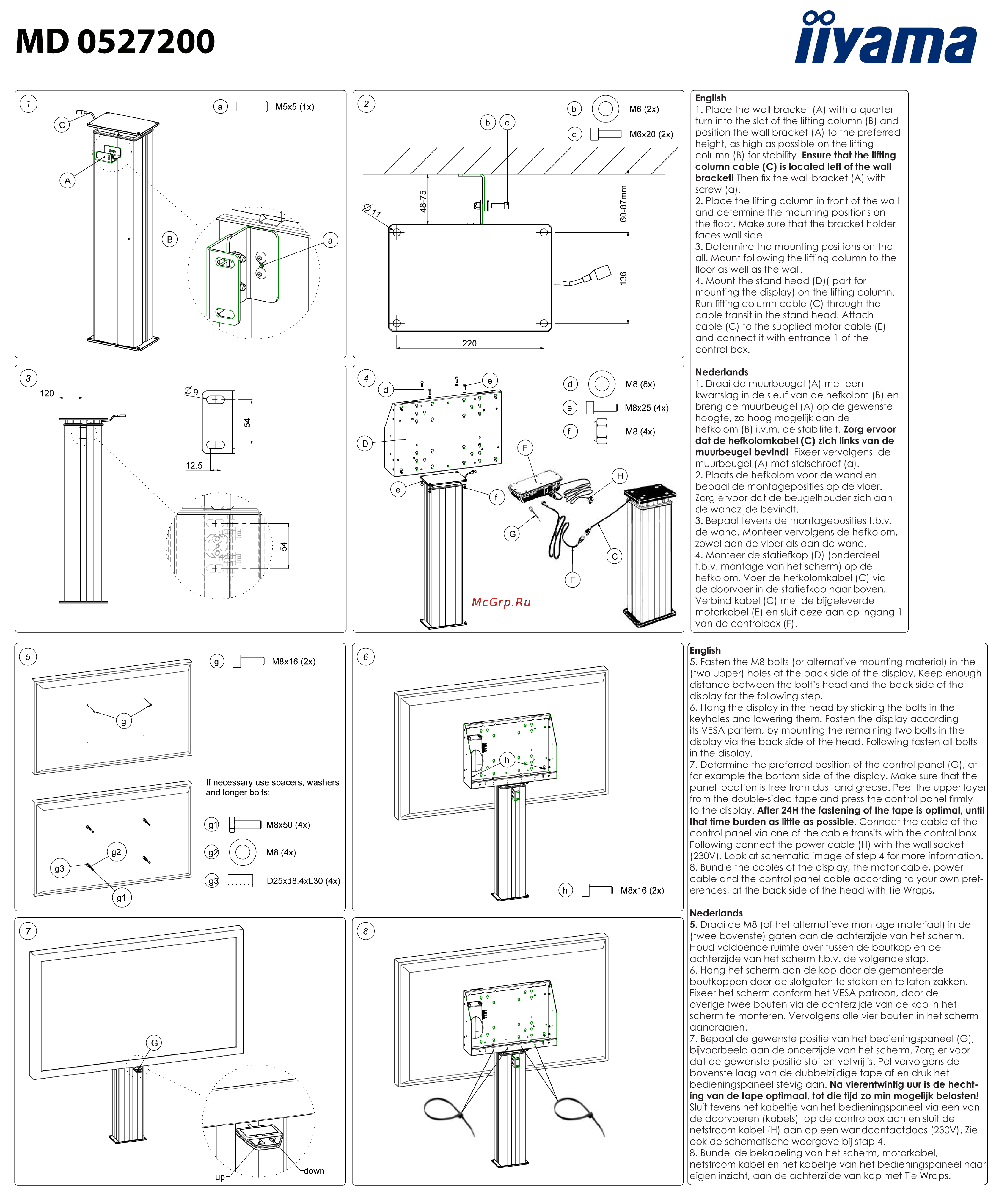
iivama MD 0527200 English 1 Place the wall bracket A with a quarter turn into the slot of the lifting column B and position the wall bracket A to the preferred height as high as possible on the lifting column B for stability Ensure that the lifting column cable C is located left of the wall bracket Then fix the wall bracket A with screw a 2 Place the lifting column in front of the wall and determine the mounting positions on the floor Make sure that the bracket holder faces wall side 3 Determine the mounting positions on the all Mount following the lifting column to the floor as well as the wall 4 Mount the stand head D part for mounting the display on the lifting column Run lifting column cable C through the cable transit in the stand head Attach cable C to the supplied motor cable E and connect it with entrance 1 of the control box Nederlands 1 Draai de muurbeugel A met een kwartslag in de sleuf van de hefkolom B en breng de muurbeugel A op de gewenste hoogte zo hoog mogelijk aan de hefkolom B i v m de stabiliteit Zorg ervoor dat de hefkolomkabel C zich links van de muurbeugel bevind Fixeer vervolgens de muurbeugel A met stelschroef a 2 Plaats de hefkolom voor de wand en bepaal de montageposities op de vloer Zorg ervoor dat de beugelhouder zich aan de wandzijde bevindt 3 Bepaal tevens de montageposities t b v de wand Monteer vervolgens de hefkolom zowel aan de vloer als aan de wand 4 Monteer de statiefkop D onderdeel t b v montage van het scherm op de hefkolom Voer de hefkolomkabel C via de doorvoer in de statiefkop naar boven Verbind kabel C met de bijgeleverde motorkabel E en sluit deze aan op ingang 1 van de controlbox F M8x16 2x English 5 Fasten the M8 bolts or alternative mounting material in the two upper holes at the back side of the display Keep enough distance between the bolt s head and the back side of the display for the following step 6 Hang the display in the head by sticking the bolts in the keyholes and lowering them Fasten the display according its VESA pattern by mounting the remaining two bolts in the display via the back side of the head Following fasten all bolts in the display 7 Determine the preferred position of the control panel G at for example the bottom side of the display Make sure that the panel location is free from dust and grease Peel the upper layer from the double sided tape and press the control panel firmly to the display After 24H the fastening of the tape is optimal until that time burden as little as possible Connect the cable of the control panel via one of the cable transits with the control box Following connect the power cable H with the wall socket 230V Look at schematic image of step 4 for more information 8 Bundle the cables of the display the motor cable power cable and the control panel cable according to your own pref erences at the back side of the head with Tie Wraps Nederlands 5 Draai de M8 of het alternatieve montage materiaal in de twee bovenste gaten aan de achterzijde van het scherm Houd voldoende ruimte over tussen de boutkop en de achterzijde van het scherm t b v de volgende stop 6 Hang het scherm aan de kop door de gemonteerde boutkoppen door de slotgaten te steken en te laten zakken Fixeer het scherm conform het VESA patroon door de overige twee bauten via de achterzijde van de kop in het scherm te monieren Vervolgens alle vier bauten in het scherm aandraaien 7 Bepaal de gewenste positie van het bedieningspaneel G bijvoorbeeld aan de onderzijde van het scherm Zorg ervoor dat de gewenste positie stof en vetvrij is Pel vervolgens de bovenste laag van de dubbelzijdige tape af en druk het bedieningspaneel stevig aan Na vierentwintig uur is de hechting van de tape optimaal tot die tijd zo min mogelijk belasten Sluit tevens het kabeltje van het bedieningspaneel via een van de doorvoeren kabels op de controlbox aan en sluit de netstroom kabel H aan op een wandcontactdoos 230V Zie ook de schematische weergave bij stop 4 8 Bündel de bekabeling van het scherm motorkabel netstroom kabel en het kabeltje van het bedieningspaneel naar eigen inzicht aan de achterzijde van kop met Tie Wraps