![Asus C60M1-I — обзор материнской платы с поддержкой AMD и DDR3 [12/54]](/img/pdf.png)
Asus C60M1-I — обзор материнской платы с поддержкой AMD и DDR3 [12/54]
![Asus C60M1-I [12/54] Motherboard layout](/views2/1163289/page12/bgc.png)
ASUS C60M1-I1-2
C60M1-I
PCIEX16
Super
I/O
F_PANEL
AAFP
ATX12V
EATXPWR
CPU_FAN
CHA_FAN
USB1112
USB910
USB78
Lithium Cell
CMOS Power
EPU
VIA
VT1708S
RTL
8111F
32Mb
BIOS
SB_PWR
CLRTC
17cm(6.7in)
17cm(6.7in)
AMD
®
FCH
A50M
(Hudson M1)
SATA6G_2
SATA6G_1
SATA6G_4
SATA6G_3
SATA6G_6
SATA6G_5
AMD
®
Fusion
APU C-60
with Radeon
TM
HD 6290 graphics
CHASSIS
ICS
9LRPS482
DDR3 DIMM1 (64bit, 240-pin module)
DDR3 DIMM2 (64bit, 240-pin module)
AUDIO
KB_USB56
LAN1_USB12
USB34
VGA
DVI
1 2 3
2
5
7891011
4
6
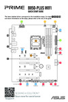
1.2.2 Layout contents
Connectors/Jumpers/Slots/LED Page Connectors/Jumpers/Slots/LED Page
1. CPU and chassis fan connectors (3-pin
CPU_FAN, 3-pin CHA_FAN)
1-11 7. Serial ATA 6.0Gb/s connectors (7-pin
SATA6G_1~6)
1-12
2. ATX power connectors (24-pin EATXPWR,
4-pin ATX12V)
1-10 8. Chassis intrusion connector (4-1 pin
CHASSIS)
1-13
3. AMD
®
Dual-core processor C-60 with AMD
®
Radeon™ HD 6290 graphics
1-3 9. Clear RTC RAM (3-pin CLRTC) 1-8
4. DDR3 DIMM slots 1-3 10. Standby power LED (SB_PWR) 1-1
5. System panel connector (10-1 pin F_PANEL) 1-13 11. Front panel audio connector (10-1 pin AAFP) 1-11
6. USB 2.0 connectors (10-1 pin USB78, USB910,
USB1112)
1-12
Place four screws into the holes indicated by circles to secure the motherboard to the
chassis. DO NOT overtighten the screws! Doing so can damage the motherboard.
Ensure that you install the motherboard into the chassis in the correct orientation. The edge
with external ports goes to the rear part of the chassis.
1.2 Motherboard overview
1.2.1 Motherboard layout
Содержание
- E7984 first edition december 2012 p.2
- Bios information p.3
- Contents p.3
- Chapter 2 p.3
- Chapter 1 p.3
- Product introduction p.3
- Contents p.4
- Contents p.5
- Appendices p.5
- Safety information p.6
- Operation safety p.6
- Electrical safety p.6
- Where to find more information p.7
- Typography p.7
- How this guide is organized p.7
- Conventions used in this guide p.7
- Bold text p.7
- About this guide p.7
- C60m1 i specifications summary p.8
- C60m1 i specifications summary p.9
- Standby power led p.11
- Product introduction p.11
- Chapter 1 p.11
- Before you proceed p.11
- Motherboard overview p.12
- Motherboard layout p.12
- Layout contents p.12
- C60m1 i p.12
- 8 9 10 11 p.12
- System memory p.13
- Overview p.13
- Hd 6290 graphics p.13
- Central processing unit cpu p.13
- C60m1 i am p.13
- C60m1 i 240 pin ddr3 dimm sockets p.13
- Apu c 60 dual core processor with radeo p.13
- Spd which is the standard way of accessing information from a memory module under the default state some memory modules for overclocking may operate at a lower frequency than the vendor marked value to operate at the vendor marked or at a higher frequency refer to section 2 ai tweaker menu for manual memory frequency adjustment p.14
- Overclocking capability p.14
- Os when you want to install 4gb or more on the p.14
- Os when you install 4gb p.14
- Os install a 64 bit window p.14
- Or more memory on the motherboard the actual usable memory for the os can be about 3gb or less for effective use of memory we recommend that you do any of the following use a maximum of 3gb system memory if you are using a 32 bit window p.14
- Motherboard p.14
- Memory load 2 dimms or overclocking condition p.14
- Memory configurations p.14
- For system stability use a more efficient memory cooling system to support a full p.14
- Due to the memory address limitation on 32 bit window p.14
- Ddr3 1333 mhz capability p.14
- You may install 512mb 1gb 2gb and 4gb unbuffered non ecc ddr3 dimms into the dimm sockets p.14
- Ddr3 1066 mhz capability p.14
- We recommend that you install the memory modules from the blue slots for better p.14
- Continued on the next page p.14
- This motherboard does not support dimms made up of 512mb 64mb chips or less p.14
- C60m1 i motherboard qualified vendors lists qvl p.14
- The default memory operation frequency is dependent on its serial presence detect p.14
- Asus c60m1 i 1 4 p.14
- Ddr3 1333 mhz capability p.15
- Continued on the next page p.15
- 5 chapter 1 product introduction p.15
- Ddr3 1333 mhz capability p.16
- Continued on the next page p.16
- Asus c60m1 i 1 6 p.16
- Dimm support p.17
- Ddr3 1333mhz memory module will run at ddr3 1066mhz frequency as default p.17
- Ddr3 1333 mhz capability p.17
- Configuration p.17
- 7 chapter 1 product introduction p.17
- 1 dimm supports one module inserted into either slot as single channel memory p.17
- Visit the asus website at www asus com for the latest qvl p.17
- Ss single sided ds double sided p.17
- Pci express x16 slot p.18
- Installing an expansion card p.18
- Expansion slots p.18
- Configuring an expansion card p.18
- Jumpers p.19
- C60m1 i clear rtc ram p.19
- Ps 2 keyboard mouse combo port this port is for a ps 2 keyboard or ps 2 mouse p.20
- Microphone port pink this port connects a microphone p.20
- Line out port lime this port connects to a headphone or a speaker in 4 channel 6 channel and 8 channel configurations the function of this port becomes front speaker out p.20
- Line in port light blue this port connects the tape cd dvd player or other audio sources p.20
- Lan rj 45 port this port allows gigabit connection to a local area network lan through a network hub refer to the table below for the lan port led indications p.20
- Lan port led indications p.20
- Connectors p.20
- Audio 2 4 6 8 channel configuration p.20
- Rear panel connectors p.20
- Video graphics adapter vga port this 15 pin port is for a vga monitor or other vga compatible devices p.21
- Usb 2 ports 5 and 6 these two 4 pin universal serial bus usb ports are for usb 2 1 devices p.21
- Usb 2 ports 3 and 4 these two 4 pin universal serial bus usb ports are for usb 2 1 devices p.21
- Usb 2 ports 1 and 2 these two 4 pin universal serial bus usb ports are for usb 2 1 devices p.21
- These connectors are for atx power supply plugs the power supply plugs are designed to fit these connectors in only one orientation find the proper orientation and push down firmly until the connectors completely fit p.21
- Internal connectors p.21
- Dvi d port this port is for any dvi d compatible device dvi d can t be converted to output rgb signal to crt and isn t compatible with dvi i p.21
- C60m1 i atx power connectors p.21
- Atx power connectors 24 pin eatxpwr 4 pin atx12v p.21
- This connector is for a chassis mounted front panel audio i o module that supports either hd audio or legacy ac 97 audio standard connect one end of the front panel audio i o module cable to this connector p.22
- Front panel audio connector 10 1 pin aafp p.22
- Cpu and chassis fan connectors 3 pin cpu_fan 3 pin cha_fan p.22
- Connect the fan cables to the fan connectors on the motherboard ensuring that the black wire of each cable matches the ground pin of the connector p.22
- C60m1 i front panel audio connector p.22
- C60m1 i fan connectors p.22
- When using hot plug and ncq set the onchip sata type item in the bios to ahci p.23
- Usb910 p.23
- Usb1112 p.23
- Usb 2 connectors 10 1 pin usb78 usb910 usb1112 p.23
- These connectors connect to serial ata 6 gb s hard disk drives via serial ata 6 gb s signal cables p.23
- These connectors are set to ide by default in ide mode you can connect serial ata p.23
- These connectors are for usb 2 ports connect the usb module cable to any of these connectors then install the module to a slot opening at the back of the system chassis these usb connectors comply with usb 2 specification that supports up to 480 mbps connection speed p.23
- The usb module cable is purchased separately p.23
- Serial ata 6 gb s connectors 7 pin sata6g_1 6 p.23
- See section 2 sata configuration for details p.23
- Never connect a 1394 cable to the usb connectors doing so will damage the motherboard p.23
- C60m1 i usb2 connectors p.23
- C60m1 i sata 6 gb s connectors p.23
- Boot data hard disk drives to these connectors p.23
- 13 chapter 1 product introduction p.23
- F_panel p.24
- C60m1 i chassis intrusion connector p.24
- C60m1 i system panel connector p.24
- Xp vista 7 operating systems os always install the latest os version and corresponding updates to maximize the features of your hardware p.25
- To run the support dvd p.25
- This motherboard supports window p.25
- The support dvd that comes with the motherboard package contains the drivers software applications and utilities that you can install to avail all motherboard features p.25
- Support dvd information p.25
- Software support p.25
- Place the support dvd to the optical drive if autorun is enabled on your computer the dvd automatically displays the specials screen click drivers utilities manual contact and specials tabs to display the respective menus p.25
- Installing an operating system p.25
- Managing and updating your bios p.27
- Chapter 2 p.27
- Bios information p.27
- Asus update utility p.27
- Asus ez flash 2 p.28
- Asus crashfree bios 3 utility p.29
- Recovering the bios p.29
- Booting the system in dos environment p.30
- Before updating bios p.30
- Asus bios updater p.30
- To backup the current bios file using the bios updater p.31
- The filename is any user assigned filename with no more than eight alphanumeric the filename is any user assigned filename with no more than eight alphanumeric characters for the filename and three alphanumeric characters for the extension p.31
- The bios updater backup screen appears indicating the bios backup process when bios backup is done press any key to return to the dos prompt p.31
- Filename extension p.31
- Ensure that the usb flash drive is not write protected and has at least 4mb free space to save the file p.31
- Chapter 2 bios information 2 5 p.31
- Backing up the current bios p.31
- Do not shut down or reset the system while updating the bios to prevent system boot failure p.32
- Disconnected them p.32
- Bios updater checks the selected bios file and prompts you to confirm bios update p.32
- After updating bios p.32
- 6 asus c60m1 i p.32
- Updating the bios file p.32
- To update the bios file using bios updater p.32
- To exit bios updater restart your computer p.32
- The bios updater screen appears as below p.32
- Reconnect all sata hard disk drives after updating the bios file if you have p.32
- Load the bios default settings to ensure system compatibility and stability select the p.32
- Load optimized defaults item under the exit menu refer to section 2 exit menu for details p.32
- For bios updater version 1 4 or later the utility automatically exits to the dos prompt p.32
- Use the bios setup program to update the bios or configure its parameters the bios screens include navigation keys and brief online help to guide you in using the bios setup program p.33
- Simultaneously p.33
- Press the reset button on the system chassis p.33
- Press the power button to turn the system off then back on do this option only if you failed to enter bios setup using the first two options p.33
- Post continues with its routines p.33
- Entering bios setup at startup p.33
- Entering bios setup after post p.33
- Bios setup program p.33
- The bios setup program can be used under two modes ez mode and advanced mode you can change modes from the exit menu or from the exit advanced mode button in the ez mode advanced mode screen p.34
- Ez mode p.34
- By default the ez mode screen appears when you enter the bios setup program the ez mode provides you an overview of the basic system information and allows you to select the display language system performance mode and boot device priority to access the advanced mode click exit advanced mode then select advanced mode p.34
- Bios menu screen p.34
- Submenu items p.35
- Menu items p.35
- Back button p.35
- Advanced mode p.35
- Scroll bar p.36
- Pop up window p.36
- Navigation keys p.36
- Main menu p.36
- General help p.36
- Configuration fields p.36
- Security p.37
- Administrator password p.37
- User password p.37
- System time xx xx xx p.37
- System language english p.37
- System date day xx xx xxxx p.37
- Ai tweaker menu p.38
- Vddnb voltage auto p.39
- Vddnb offset mode sign p.39
- Memory frequency auto p.39
- Dram timing control p.39
- Cpu voltage auto p.39
- Cpu offset mode sign p.39
- Apu frequency xxx p.39
- Ai overclock tuner auto p.39
- Apu spread spectrum auto p.40
- Apu 1 v voltage auto p.40
- Apu 1 5v voltage auto p.40
- Sb 1 v voltage auto p.40
- Dram voltage auto p.40
- Svm mode enabled p.41
- Pstate adjustment pstate 0 p.41
- Nx mode enabled p.41
- Cpu configuration p.41
- Cpb mode auto p.41
- Cool n quiet enabled p.41
- C6 mode enabled p.41
- Advanced menu p.41
- S m a r t status check enabled p.42
- Onchip sata type ide p.42
- Onchip sata speed auto p.42
- Onchip sata channel enabled p.42
- Legacy usb support enabled p.42
- Ehci hand off disabled p.42
- Usb configuration p.42
- Sata configuration p.42
- Restore ac power loss power off p.43
- Realtek pxe oprom disabled p.43
- Realtek lan controller enabled p.43
- Primary video device pcie video p.43
- Onboard devices configuration p.43
- Nb configuration p.43
- Integrated graphics auto p.43
- Igfx multi monitor disabled p.43
- Hd audio device enabled p.43
- Front panel type hd p.43
- Eup ready disabled p.43
- Power on by ps 2 keyboard disabled p.44
- Power on by pme disabled p.44
- Monitor menu p.44
- Power on by ps 2 mouse disabled p.44
- Cpu temperature mb temperature xxxºc xxxºf p.45
- Cpu q fan control enabled p.45
- Cpu fan speed low limit 600 rpm p.45
- Cpu chassis fan speed xxxx rpm or ignore n a p.45
- Chassis q fan control enabled p.45
- Cpu voltage 3 v voltage 5v voltage 12v voltage p.46
- Chassis fan speed low limit 600 rpm p.46
- Anti surge support enabled p.46
- Post report 5 sec p.47
- Option rom messages force bios p.47
- Full screen logo enabled p.47
- Bootup numlock state on p.47
- Boot menu p.47
- Boot override p.48
- Boot option priorities p.48
- Setup mode ez mode p.48
- Tools menu p.49
- To display the submenu p.49
- This utility stores or loads multiple bios settings p.49
- Save to profile p.49
- Press enter to launch the asus ez flash 2 screen p.49
- Load from profile p.49
- Asus o c profile p.49
- Asus ez flash 2 utility p.49
- And then select yes p.49
- Save changes reset p.50
- Load optimized defaults p.50
- Launch efi shell from filesystem device p.50
- Exit menu p.50
- Discard changes exit p.50
- Asus ez mode p.50
- Notices p.51
- Ic canadian compliance statement p.51
- Federal communications commission statement p.51
- Appendices p.51
- Vcci japan compliance statement p.52
- Vcci class b statement p.52
- Kc korea warning statement p.52
- Canadian department of communications statement p.52
- Asus recycling takeback services p.52
- Technical support p.53
- Asustek computer inc p.53
- Asus contact information p.53
- Asus computer international america p.53
- Asus computer gmbh germany and austria p.53
- Asus computer international p.54
- A 4 asus c60m1 i p.54
- Ec declaration of conformity p.54
- Declaration of conformity p.54
- Ca 94539 p.54
Похожие устройства
-
 Asus PRIME A520M-A IIКраткое руководство пользователя
 -
 Asus ProArt B650-CREATORКраткий обзор функций
 -
 Asus Pro WS W680M-ACE SEКраткая эксплуатационная инструкция
 -
 Asus B850-PLUS WIFIКраткое руководство
 -
 Asus TUF GAMING H470-PROКраткое руководство
 -
 Asus PRIME H610M-F D4Быстрый старт
 -
 Asus PRIME TRX40-PRO SКраткое руководство
 -
 Asus PRIME A620M-AКраткий обзор функций
 -
 Asus E2KM1I-DELUXEРуководство по быстрому запуску
 -
 Asus ROG STRIX X570-E GAMING WIFI IIКраткое руководство
 -
 Asus TUF GAMING B550M-EКраткое руководство пользователя
 -
 Asus PRIME H810M-AКраткий обзор функций
Изучите характеристики материнской платы с поддержкой AMD, включая разъемы, слоты и особенности подключения. Узнайте, как правильно установить плату в корпус.