![Supermicro SC846E16-R1200B [80/160] Removing the chassis from the rack](/img/pdf.png)
Supermicro SC846E16-R1200B [80/160] Removing the chassis from the rack
![Supermicro SC846E16-R1200B [80/160] Removing the chassis from the rack](/views2/1190280/page80/bg50.png)
SC846 Chassis Manual
5-8
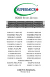
Figure 5-5. Removing the Chassis From the Rack
Removing the Chassis from the Rack
Caution! It is dangerous for a single person to off-load the heavy chassis from the
rack without assistance. Be sure to have sufcient assistance supporting the chassis
when removing it from the rack. Use a lift.
Removing the Chassis from the Rack
1. Pull the chassis forward out the front of the rack until it stops.
2. Press the release latches on each of the inner rails downward simultaneously
and move the chassis forward in the rack.
1
2
Содержание
- User s manual p.1
- Warning handling of lead solder materials used in this product may expose you to lead a chemical known to the state of california to cause birth defects and other reproductive harm p.2
- Warnings p.3
- Preface p.3
- About this manual p.3
- Contents p.4
- Chapter 3 system interface 1 p.4
- Chapter 2 standardized warning statements for ac systems 1 p.4
- Chapter 1 introduction 1 p.4
- Chapter 5 rack installation 1 p.5
- Chapter 4 chassis setup and maintenance 1 p.5
- Appendix e bpn sas3 846el backplane specifications e 1 p.6
- Appendix d sas2 846el backplane specifications d 1 p.6
- Appendix c sas 846el backplane specifications c 1 p.6
- Appendix b sas 846tq backplane specifications b 1 p.6
- Appendix a power supply specifications a 1 p.6
- Contacting supermicro p.7
- Sc846be1c r1k28b p.9
- Sc846be2c r1k28b p.9
- Sc846be26 r920b p.9
- Sc846be26 r1k28b p.9
- Sc846be16 r920b p.9
- Sc846be16 r1k28b p.9
- Sc846ba r920b p.9
- Sc846ba r1k28b p.9
- Sc846 chassis models p.9
- Optimized for enterprise level high capacity storage applications supermicro s sc846 chassis features 24 hot swap 3 sas sata hard drive trays and 2 fixed internal hard drive bays in a 4u form factor the design offers maximum hdd per space ratio high power efficiency optimized hdd signal trace routing and improved hdd tray design to dampen hdd vibrations and maximize performance equipped high efficiency redundant power supplies and five hot swap redundant cooling fans the sc846 is a reliable and trouble free storage system p.9
- Model hdd pci slots power supply p.9
- Introduction p.9
- Chapter 1 introduction p.9
- Chapter 1 p.9
- 1 overview p.9
- Sc846e26 r1200b p.9
- Sc846e16 r1200b p.9
- Power supply p.10
- Drives p.10
- Cooling p.10
- 3 components p.10
- 2 shipping list p.10
- Mounting rails p.11
- Motherboard p.11
- Expansion slots p.11
- 5 returning merchandise for service p.11
- 4 where to get replacement components p.11
- 6 contacting supermicro p.12
- Standardized warning statements for ac systems p.13
- Chapter 2 p.13
- About standardized warning statements p.13
- Warning definition p.13
- ןונקת תורהצהאהרהז ןה תואבה תורהצהא ינפמ שמתשמה תא ריהזהל תנמ לע היישעתה ינקת יפ לע תורהז הלבח ה וא תולאש שיו הדימב תירשפא תיזיפי יהשלכ היעבב תולקתרוציל שי הכימת תקלחמ םע רשק רידגהל וא ןיקתהל םיאשר דבלב םיכמסומ םיאנכט ורקימרפוס לש תינכט תאה םיביכר אורקל שי ורקימרפוס יזראמב םיביכרה תרדגה וא תנקתה ינפל ואולמב חפסנה תא p.14
- ف ك ا ىأ يكو ةلاح ف ببستت ةباصا ة ذسج زهزلا اذه ع زطخ ز ذحت ىأ لبق يأ ىلع لوعت تاذعه كنلع ىلع ي يع ةوجا لا زطاخولاب زئاوذلا ة ئابزهكلا كوة ارد ىلع ي راوولابتاس ة ئاقىلا ل ع وعىقو يأثداىح نقر مذختسا ىا بلا صىص ولا ة اه ف ز ذحت لك رىثعلل اهتوجزت p.15
- لا تاداشرإ رقابيكرت ليصوت لبق ىلإ ماظنلا ةقاطلل ردصم p.16
- אורקל שי רוקמל תכרעמה רוביח ינפל הנקתה תוארוה תאחתמ אורקל שי רוקמל תכרעמה רוביח ינפל הנקתה תוארוה תאחתמ p.16
- Installation instructions p.16
- نم دكأت نأ مييقت زاهجلا لايئاقو سيل نم رثكأ p.17
- جتنملا اذه ىلع دمتعي ثادعم تيامحلا ةريصقلارئاودلا هم اهتيبثت مت يتلا يف ىنبملا p.17
- לע ךמתסמ הז רצומנגהה תעינמל םינבמב תנקתומה יכ אדוול שי ילמשח רצק רצקה ינפמ ןגמה רישכמה ילמשחהמ רתוי אל אוה p.17
- Circuit breaker p.17
- Power disconnection warning p.18
- مصف بجي واظننا عيمج نمرداصم تقاطنا تنازإو ءابرهكنا كهس نم ةدحو دادما تقاطنا مبق ىنإ لىصىنا تيهخادنا قطانمنا نمكيهه تنازإ وأ جيبثتن ثانىكم زاهجلا p.19
- ילמשח קותינ ינפמ הרהזא p.19
- הרהזא למשחה תורוקמ לכמ תכרעמה תא קתנל שי ריסהל שיו קפסהמ ילמשחה לבכ תא נקתה ךרוצל זראמה לש ימינפה קלחל השיג ינפלת רסה ואת םיביכר p.19
- הרהזא שר דבלב ךמסומ תווצתא ףילחהל ןיקתהל יא דויצה רובע תוריש תתל וא דויצה p.20
- Equipment installation p.20
- هيبردملاو و بيكزتللادبتسا وأ ةمدخ ساهجلا اذه حمسي نأ بجي طقف هيلهؤملا هيفظىملل p.20
- Restricted area p.21
- صيصخت ةذحىنا هذه ف اهب كرتن قطانم ةروظحم مت صىنا نكم نإ لى تقطنم ةروظحم طقف واذختسا للاخ نم تصاخ ةادأ وأ أ لان يرخأ ته سو املأم حاتفمو مفق p.22
- תלבגומ השיג םע רוזא הרהזא תרזעב תנתינ השיגה השיג תלבגה םהב שיש םירוזאב הדיחיה תא ןיקתהל שי דכו לוענמ חתפמ דבלב החטבא ילכ p.22
- Battery handling p.22
- رطخ كانه نم لاذبحسا ةلاح يف راجفنا ةيراطبلا ةحيحص ريغ ةقيرطب ليلعف ةيراطبلا لاذبحسا طقف عىنلا سفنب اهلداعي ام وأ اممثصوأ ةعنصملا ةمرشلا هب تايراطبلا نم صلخج ل اقفو ةلمعحسملاةعناصلا ةمرشلا تاميلعح p.23
- הרהזא תנכס תמייקץוציפ הניקת אל ךרדב הפלחוהו הדימב הללוסה לש ףילחהל שי גוסב הללוסה תא מ םאותה תרבחלמומ ןרציתצ תוללוסה קוליס תושמושמה עצבל שי ןרציה תוארוה יפל p.23
- חיה תאי הד p.24
- דחא קפסמ רתוי םייק םא הרהזא קפס לש דחא רוביחמ רתוי שי הדחיל תא ריסהל שי ןקורל תנמ לע םירוביחה לכ p.24
- Redundant power supplies p.24
- دق اذهل نوكي لازاهج تلااصتا ةدع تادحوب ةقاطلا دادما ةلازإ بجي تلااصتلاا ةفاك لسعل لاةدحو نع ءابرهكلا p.25
- Backplane voltage p.25
- كانه زطخ هم يئابزهكلا رايتلا ىلع ةدىجىملا ةقاطلاوأ ةحىللا نىكي امدنعماظنلا لمعي دنع ارذح هك ةمدخ ساهجلا اذه p.26
- ירוחאה לנפב חתמ זא הרה ךלהמב רהזיהל שי תכרעמה לועפת ןמזב ירוחאה לנפב חתמ תנכס תמייק הדובעה p.26
- Comply with local and national electrical codes p.26
- Product disposal p.27
- تادعملا بيكرت ةيئابرهكلا لل لثتمي نأ بجي هيواىقةيىطىلاو ةيلحملا ةقلعتملا ءابرهكلاب p.27
- יצראה למשחה יקוח םואית הרהזא תנקתה םייצראהו םיימוקמה למשחה יקוחל תמאות תויהל תבייח דויצה p.27
- يئاهنلا صلختلا نم جتنملا اذه هعم لماعتلا يغبني ل اقفو عيمجةينطىلا حئاىللاو نيناىقلا دنع p.28
- רצומה קוליס הרהזא ו תויחנהל םאתהב תויהל בייח הז רצומ לש יפוס קוליס הנידמה יקוח p.28
- Hot swap fan warning p.28
- هكممنا هم حوارمنا نأ لاست لا ةنازإ دنعرودت ةهتك ةحورمنا مكيهنا هم بجي ءاقبإ p.29
- عباصلأا ويغاربنا تاكفم ءايشلأا هم اهريغو اديعب هع تاحتفنا يف ةهتك ةحورمنا p.29
- הרהזא יקלח תא םיריסמ רשאכ שי םידבוע ןיידע םיררוואמהו ןכתי זראמהמ ררוואמה קיחרהללררוואמה ךותב םיחתפהמ םינוש הדובע ילכו תועבצאה תא חוטב קחרמ p.29
- Power cable and ac adapter p.30
- System interface p.33
- Chapter 3 p.33
- 1 overview p.33
- 3 control panel leds p.34
- 2 control panel buttons p.34
- Power fail p.35
- Information led p.35
- Sc846 chassis manual p.36
- There are several possible responses if the system overheats p.36
- The chassis includes externally accessible sas sata drives each drive carrier p.36
- Status led p.36
- Some backplanes allow the overheat temperature to be set at 45 50 or 55 by changing a jumper setting for more information consult the backplane user manual at www supermicro com click support then the manuals link p.36
- Responses p.36
- Overheating p.36
- Overheat temperature setting p.36
- Normally p.36
- Led color blinking pattern behavior for device p.36
- If the server overheats p.36
- Displays two status leds on the front of the carrier p.36
- Confirm that the chassis covers are installed properly p.36
- Check the routing of the cables and make sure all fans are present and operating p.36
- Verify that the heatsinks are installed properly p.36
- Activity led p.36
- Use the leds to determine the nature of the overheating condition p.36
- 4 drive carrier leds p.36
- 5 power supply leds p.37
- Chassis setup and maintenance p.39
- Chapter 4 p.39
- 1 overview p.39
- 2 removing power from the system p.40
- 3 removing the chassis cover p.41
- 4 installing front hard drives p.42
- I o shield p.45
- 5 installing the motherboard p.45
- Hard drive p.46
- Figure 4 9 chassis standoffs p.46
- Dvd rom cd rom and floppy drive p.46
- As required by your motherboard install standoffs in any areas that do not p.46
- As described in section 4 1 p.46
- With component placement requirements precautions and cable connections p.46
- Standoffs prevent short circuits by securing space between the motherboard and the chassis surface the sc846 chassis includes permanent standoffs in locations used by most motherboards these standoffs accept the rounded phillips head screws included in the sc846 accessories packaging p.46
- Some motherboards require additional screws for heatsinks general components and or non standard security optional standoffs are included to these motherboards to use an optional standoff you must place the hexagonal screw through the bottom the chassis and secure the screw with the hexagon nut rounded side up p.46
- Sc846 chassis manual p.46
- Review the documentation that came with your motherboard become familiar p.46
- Power down the system as described in section 4 2 and open the chassis cover p.46
- Permanent and optional standoffs p.46
- M b standoffs p.46
- Installing the motherboard p.46
- Have a permanent standoff to do this a place a hexagonal standoff screw through the bottom the chassis b secure the screw with the hexagon nut rounded side up p.46
- 6 expansion card setup p.48
- 7 installing the air shroud p.49
- 8 checking the airflow p.50
- 9 system fans p.51
- 10 power supply p.53
- 11 changing the power distributor p.55
- Fixed internal hard drives p.57
- 12 optional drives p.57
- Installing a dvd drive p.60
- Installing the hot swap hard drive assembly p.64
- 13 accessing the backplane p.68
- Rack installation p.73
- Choosing a setup location p.73
- Chapter 5 p.73
- 2 preparing for setup p.73
- 1 unpacking the system p.73
- Rack precautions p.74
- General server precautions p.74
- 3 warnings and precautions p.74
- Rack mounting considerations p.75
- Circuit overloading p.75
- Ambient operating temperature p.75
- Sufficient airflow p.75
- Reliable ground p.75
- Identifying the inner rack rails p.76
- 4 procedure for rack mounting p.76
- Installing the inner rails on the chassis p.77
- Installing the outer rails onto the rack p.78
- Installing the chassis into a rack p.79
- Removing the chassis from the rack p.80
- Power supply specifications p.81
- Appendix a p.81
- Sas 846tq backplane specifications p.83
- B 2 general safety guidelines p.83
- B 1 esd safety guidelines p.83
- Appendix b p.83
- B 4 introduction to the sas 846tq backplane p.84
- B 3 a note to users p.84
- Front connectors p.85
- B 4 rear connectors and jumpers p.85
- B 5 rear connector and pin definitions p.87
- The sideband headers are designated jp66 jp68 jp75 jp77 jp112 and jp114 for ses 2 to work properly you must connect an 8 pin sideband cable see the table to the right for pin definitions p.88
- The sas ports are used to connect the sas drive cables the twenty four ports are desig nated 0 23 each port is also compatible with sata drives p.88
- The 4 pin connectors designated jp10 jp13 jp46 jp48 jp109 and jp110 provide power to the backplane see the table on the right for pin definitions p.88
- Sc846 chassis manual p.88
- Note sgpio is the default setting for this backplane p.88
- Backplane main power connectors p.88
- 9 sideband headers p.88
- 34 sas ports p.88
- B 6 rear jumper locations and pin definitions p.89
- Fan jumper settings p.90
- C and sgpio modes and jumper settings p.91
- Rear led indicators p.92
- D45 d47 d49 d51 d3 d36 d89 d53 d54 p.92
- Fail 0 p.93
- B 7 front connectors and led indicators p.93
- Sas 846el backplane specifications p.95
- C 2 general safety guidelines p.95
- C 1 esd safety guidelines p.95
- Appendix c p.95
- C 4 introduction to the sas 846el backplane p.96
- C 3 an important note to users p.96
- Rear connectors p.97
- Pwr5 pwr3 p.97
- Fan2 fan1 p.97
- Designed in usa p.97
- C 5 rear connectors and jumpers p.97
- 5v 12v gnd gnd 5v 12v gnd gnd 5v 12v gnd gnd p.97
- 5v 12v gnd gnd 5v p.97
- 5v 12v gnd gnd p.97
- Sec_j2 sec_j1 sec_j0 pri_j2 pri_j1 pri_j0 p.97
- Rev 1 1 p.97
- C 6 rear connector and pin definitions p.98
- Remote_fan_fail_socket1 p.100
- Pwr5 pwr3 p.100
- Pri_ mode1 p.100
- Overheatfail1 fanfail1 p.100
- Figure c 2 rear jumper locations and pin defimitions p.100
- Fan2 fan1 p.100
- Explanation of jumpers p.100
- Designed in usa p.100
- C 7 rear jumper locations and pin definitions p.100
- Buzzer_enb1 p.100
- 5v 12v gnd gnd 5v 12v gnd gnd 5v 12v gnd gnd p.100
- To modify the operation of the backplane jumpers can be used to choose between optional settings jumpers create shorts between two pins to change the function of the connector pin 1 is identified with a square solder pad on the printed circuit board note on two pin jumpers closed means the jumper is on and open means the jumper is off the pins p.100
- 5v 12v gnd gnd 5v p.100
- 5v 12v gnd gnd p.100
- Sec_mode1 p.100
- Sec_j2 sec_j1 sec_j0 pri_j2 pri_j1 pri_j0 p.100
- Sc846 chassis manual p.100
- Rev 1 1 p.100
- Sas 9 sas sata hdd 9 sas 21 sas sata hdd 21 p.102
- Sas 13 p.102
- Sas 8 sas sata hdd 8 sas 20 sas sata hdd 20 p.102
- Sas 12 p.102
- Sas 7 sas sata hdd 7 sas 19 sas sata hdd 19 p.102
- Sas 11 sas sata hdd 11 sas 23 sas sata hdd 23 p.102
- Sas 6 sas sata hdd 6 sas 18 sas sata hdd 18 p.102
- Sas 10 sas sata hdd 10 sas 22 sas sata hdd 22 p.102
- Sas 5 sas sata hdd 5 sas 17 sas sata hdd 17 p.102
- Sas 1 sas sata hdd 1 sas 13 sas sata hdd 13 p.102
- Sas 5 sas 11 sas 17 sas 23 p.102
- Sas 0 sas sata hdd 0 sas 12 sas sata hdd 12 p.102
- Sas 4 sas sata hdd 4 sas 16 sas sata hdd 16 p.102
- Number p.102
- Front sas sata connectors p.102
- Sas 4 sas 10 sas 16 sas 22 p.102
- Figure c 3 front connectors p.102
- Sas 3 sas sata hdd 3 sas 15 sas sata hdd 15 p.102
- Connector p.102
- Sas 21 p.102
- C 8 front connectors and led indicators p.102
- Sas 20 p.102
- Sas 2 sas sata hdd 2 sas 14 sas sata hdd 14 p.102
- Sas 19 p.102
- Sas 18 p.102
- Sc846 chassis manual p.102
- Sas 15 p.102
- Sas drive p.102
- Sas 14 p.102
- The following section contains cascading configurations for the sc846el1 and sc846el2 backplanes p.104
- Single ports p.104
- Sc846 chassis manual p.104
- Sas 846el2 backplanes have dual port expanders that access all twenty four drives these dual port expanders support cascading failover and multipath p.104
- Sas 846el1 backplanes have a single port expander that access all twenty four drives and supports cascading p.104
- J2 j2 j1 p.104
- Figure c 5 sas 846el1 single port configuration p.104
- Figure c 4 sas 846el2 dual port configuration p.104
- Dual ports p.104
- C 9 dual port and cascading configurations p.104
- C 10 single and dual port expanders p.104
- Single host bus adapter failover p.105
- Single host bus adapter p.105
- C 11 failover p.105
- Dual host bus adapter failover p.106
- Dual host bus adapter p.106
- C 12 failover with raid cards and multiple hbas p.106
- Jbpwr2 p.107
- Chassis power card p.107
- C 13 chassis power card and support cables p.107
- Supported internal hba cables p.108
- Connecting an internal host bus adapter to the backplane p.108
- Single external host bus adapter p.110
- Dual external host bus adapter p.110
- Connecting an external host bus adapter to the backplane p.110
- Supported external hba to backplane cable p.111
- External cable p.112
- Connecting multiple backplanes in a single channel environment p.112
- Cbl 0167l p.112
- Cbl 0166l p.112
- With single port assembly p.112
- This section describes the cables used when cascading from a single hba these connections use cbl 0167l internal cables and cbl 0166l external cables p.112
- Sc846 chassis manual p.112
- Power card p.112
- Port b expander 2 port a expander 1 p.112
- Port b expander 2 p.112
- Port a expander 1 p.112
- Internal cable p.112
- Figure c 16 single hba configuration p.112
- Single hba configuration cables p.113
- Connecting multiple backplanes in a dual channel environment p.114
- Dual hba configuration cables p.115
- Cable 0167l p.116
- Cable 0166l p.116
- C 14 supported cascading configurations p.116
- Assembly p.116
- The first backplane in a cascaded system requires a motherboard and hba other servers require a power control card with no motherboard and no hba for more information see the sc846 chassis manual available at www supermicro com p.116
- Single port cable p.116
- Sc846 chassis manual p.116
- Power card p.116
- Port b expander 2 port a expander 1 p.116
- Internal cable p.116
- Figure c 22 simple cascaded configuration p.116
- External cable p.116
- Cascading allows the system to access data at a faster rate by allowing several backplanes to share resources to reduce latency time p.116
- Internal cable p.117
- Figure c 23 cascaded configuration with horizontal branching p.117
- External cable p.117
- Cable 0167l p.117
- Cable 0166l p.117
- Assembly p.117
- Appendix c sas 846el backplane specifications p.117
- The expanders allow horizontal branching this configuration also applies to dual ports p.117
- Single port cable p.117
- Server system with single sas hba p.117
- Power card p.117
- Port a expander 1 p.117
- Port b expander 2 p.118
- Port a expander 1 p.118
- Internal cable p.118
- Important see section c 12 of this manual failover with raid cards and multiple hbas for important information on supported configurations p.118
- Figure c 24 dual sas hba with cascaded configuration p.118
- External cables p.118
- Dual sas hba and cascaded configuration p.118
- Dual port cable p.118
- Cable 0168l p.118
- Cable 0166l p.118
- Assembly p.118
- Sc846 chassis manual p.118
- Power card p.118
- Power card p.119
- Dual sas hba and cascaded configuration with branching p.119
- Sas2 846el backplane specifications p.121
- D 2 general safety guidelines p.121
- D 1 esd safety guidelines p.121
- Appendix d p.121
- D 4 introduction to the sas2 846el backplane p.122
- D 3 an important note to users p.122
- Xxx xx x p.123
- Decimal p.123
- Tolerances p.123
- Date 2010 4 5 p.123
- Tel 408 503 8000 fax 408 503 8008 p.123
- D 5 rear connectors and jumpers p.123
- Specified dimensions unless otherwise p.123
- Bpn sas2 846el2 p.123
- Silkscreen primary side p.123
- Are in inches p.123
- Shen ping desinger p.123
- 5v 12v gnd gnd p.123
- Sec_j0 sec_j1 sec_j2 p.123
- San jose ca 95131 p.123
- Rrrrrrrrrr p.123
- Rev 1 0 p.123
- Rear connectors p.123
- Project name p.123
- Pri_j0 p.123
- Mach finish p.123
- Designed in usa p.123
- Designed by supermicro u s a www supermicro com p.123
- This primary and secondary expander chips allow the backplane to support dual ports cascading and failover p.124
- The epp ports are used for manufacturer diagnostic purposes only p.124
- The 4 pin connectors designated pwr1 pwr2 pwr3 pwr4 pwr5 and pwr6 provide power to the backplane see the table on the right for pin definitions p.124
- Sc846 chassis user s manual p.124
- Primary p.124
- Epp ports p.124
- D 6 rear connector and pin definitions p.124
- C connector is used to monitor the power supply status and to control the fans see the table on the right for pin definitions p.124
- C connector p.124
- Backplane main power connectors p.124
- And 4 primary and secondary expander chips p.124
- Rev 1 0 p.126
- Buzzer_enb1 p.126
- Bpn sas2 846el2 p.126
- Project name p.126
- Are in inches p.126
- Xxx xx x p.126
- Pri_mode2 p.126
- Actled1 p.126
- Uart_p uart_s expdbg1 p.126
- Pri_mode1 p.126
- 5v 12v gnd gnd p.126
- Tolerances p.126
- Pri_j0 p.126
- To modify the operation of the backplane jumpers can be used to choose between optional settings jumpers create shorts between two pins to change the function of the connector pin 1 is identified with a square solder pad on the printed circuit board note on two pin jumpers closed means the jumper is on and open means the jumper is off the pins p.126
- Mach finish p.126
- Tel 408 503 8000 fax 408 503 8008 p.126
- Figure d 2 rear jumper locations and settings p.126
- Specified dimensions unless otherwise p.126
- Fanfail_led_disable p.126
- Silkscreen primary side p.126
- Fan_monitor_disable p.126
- Shen ping desinger p.126
- Explanation of jumpers p.126
- Sec_mode2 p.126
- Expdbg2 p.126
- Sec_mode1 p.126
- Designed in usa p.126
- Sec_j0 sec_j1 sec_j2 p.126
- Designed by supermicro u s a www supermicro com p.126
- Sc846 chassis user s manual p.126
- Decimal p.126
- San jose ca 95131 p.126
- Date 2010 4 5 p.126
- Rrrrrrrrrr p.126
- D 7 rear jumper locations and settings p.126
- Sas 23 p.128
- Project name p.128
- Designed by supermicro u s a www supermicro com p.128
- Tolerances p.128
- Act 12 fail 12 p.128
- Number p.128
- Decimal p.128
- Tel 408 503 8000 fax 408 503 8008 p.128
- Act 11 fail 11 act 9 fail 9 act 8 fail 8 p.128
- Sas 22 p.128
- Mach finish p.128
- Date 2010 4 5 p.128
- Specified dimensions unless otherwise p.128
- Sas 21 p.128
- Front sas sata connectors p.128
- D 9 front connectors and led indicators p.128
- Shen ping desinger p.128
- Sas 20 p.128
- Figure d 3 front connectors p.128
- Connector p.128
- Sc846 chassis user s manual p.128
- Sas 2 sas sata hdd 2 sas 14 sas sata hdd 14 p.128
- Fail 5 act 5 p.128
- Bpn sas2 846el2 p.128
- Sas sas p.128
- Sas 19 p.128
- Are in inches p.128
- Sas drive p.128
- Sas 18 p.128
- Fail 23 p.128
- Act 7 fail 7 act 6 fail 6 p.128
- Sas 9 sas sata hdd 9 sas 21 sas sata hdd 21 p.128
- Sas 15 p.128
- Fail 22 p.128
- Act 4 fail 4 p.128
- Sas 8 sas sata hdd 8 sas 20 sas sata hdd 20 p.128
- Sas 14 p.128
- Fail 21 p.128
- Act 3 fail 3 act 2 fail 2 p.128
- Sas 7 sas sata hdd 7 sas 19 sas sata hdd 19 p.128
- Sas 13 p.128
- Fail 20 act 20 p.128
- Act 23 p.128
- Sas 6 sas sata hdd 6 sas 18 sas sata hdd 18 p.128
- Sas 12 p.128
- Fail 18 p.128
- Sas 5 sas sata hdd 5 sas 17 sas sata hdd 17 p.128
- Sas 11 sas sata hdd 11 sas 23 sas sata hdd 23 p.128
- Fail 13 act 13 p.128
- Act 22 p.128
- Sas 5 sas 11 sas 17 p.128
- Sas 10 sas sata hdd 10 sas 22 sas sata hdd 22 p.128
- Fail 11 act 11 fail 16 act 16 fail 15 act 15 fail 14 p.128
- Act 21 p.128
- Sas 4 sas sata hdd 4 sas 16 sas sata hdd 16 p.128
- Sas 1 sas sata hdd 1 sas 13 sas sata hdd 13 p.128
- Fail 10 act 10 p.128
- Act 19 fail 19 p.128
- Sas 4 sas 10 sas 16 p.128
- Sas 0 sas sata hdd 0 sas 12 sas sata hdd 12 p.128
- Fail 1 p.128
- Act 18 p.128
- Sas 3 sas sata hdd 3 sas 15 sas sata hdd 15 p.128
- San jose ca 95131 p.128
- Fail 0 p.128
- Xxx xx x p.128
- Act 14 p.128
- Rrrrrrrrrr p.130
- Rev 1 0 p.130
- Project name p.130
- Pri_j0 p.130
- Xxx xx x p.130
- Mach finish p.130
- Tolerances p.130
- Figure d 4 dual port cascading configurations p.130
- Dual ports p.130
- Tel 408 503 8000 fax 408 503 8008 p.130
- Designed in usa p.130
- Specified dimensions unless otherwise p.130
- Designed by supermicro u s a www supermicro com p.130
- Single ports p.130
- Decimal p.130
- Silkscreen primary side p.130
- Date 2010 4 5 p.130
- Shen ping desinger p.130
- Sec_j0 sec_j1 sec_j2 p.130
- D 10 single and dual port expanders p.130
- Sc846 chassis user s manual p.130
- Bpn sas2 846el2 p.130
- Sas2 846el2 backplanes have dual port expanders that access all the hard drives these dual port expanders support cascading failover and multipath p.130
- Are in inches p.130
- Sas2 846el1 backplanes have a singld port expander that accesses all hard drives and supports cascading p.130
- 5v 12v gnd gnd p.130
- San jose ca 95131 p.130
- Bpn sas2 846el2 p.131
- Tolerances p.131
- Pri_j0 p.131
- Are in inches p.131
- The sas2 846el2 backplane has two expanders which allow effective failover p.131
- Mach finish p.131
- Appendix d sas2 846el backplane specifications p.131
- Tel 408 503 8000 fax 408 503 8008 p.131
- In a single host bus configuration the backplane connects to one host bus adapter hba p.131
- 5v 12v gnd gnd p.131
- Specified dimensions unless otherwise p.131
- In a dual host bus configuration the backplane connects to two host bus adapters p.131
- Single host bus adapter failover p.131
- If the expander or data path in the primary ports fails the system automati cally switches to secondary ports p.131
- Single host bus adapter p.131
- If the expander or data path in the primary ports fails the system auto matically switches to the secondary ports this maintains a full connection to all drives p.131
- Silkscreen primary side p.131
- Figure d 5 failover configurations p.131
- Shen ping desinger p.131
- Expander 2 p.131
- Secondary ports p.131
- Expander 1 p.131
- Sec_j0 sec_j1 sec_j2 p.131
- Dual host bus adapter failover p.131
- Sas hba p.131
- Dual host bus adapter p.131
- San jose ca 95131 p.131
- Designed in usa p.131
- Rrrrrrrrrr p.131
- Designed by supermicro u s a www supermicro com p.131
- Rev 1 0 p.131
- Decimal p.131
- Project name p.131
- Date 2010 4 5 p.131
- Primary ports p.131
- D 11 failover p.131
- Xxx xx x p.131
- D 12 chassis power card and support cables p.132
- Cse ptjbod cb2 p.132
- Chassis power card p.132
- Tolerances p.133
- Designed in usa p.133
- The following section lists the most common cables used to connect the host bus p.133
- Designed by supermicro u s a www supermicro com p.133
- Tel 408 503 8000 fax 408 503 8008 p.133
- Description this cable has one sff 8484 32 pin connector on one end and ipass sff 8087 mini sas connector 36 pins at the other this cable connects from the hba to the sas2 846el backplane p.133
- Supported internal hba cables p.133
- Decimal p.133
- Specified dimensions unless otherwise p.133
- Date 2010 4 5 p.133
- Connecting an internal host bus adapter to the backplane p.133
- Shen ping desinger p.133
- Cable name ipass to 4 lane p.133
- Sec_j0 sec_j1 sec_j2 p.133
- Bpn sas2 846el2 p.133
- San jose ca 95131 p.133
- Are in inches p.133
- Rrrrrrrrrr p.133
- Appendix d sas2 846el backplane specifications p.133
- Rev 1 0 p.133
- Adapter to the backplane p.133
- Project name p.133
- Pri_j0 p.133
- 5v 12v gnd gnd p.133
- Part cbl 0117l length 46 cm 18 inches p.133
- Mach finish p.133
- Xxx xx x p.133
- Hba hba p.133
- Use the following listed cables to create connections between the internal hba and sas2 846el backplane the cables required depend on the hba connector p.133
- Figure d 7 connecting an internal hba to the backplane p.133
- Supported external hba to backplane cable p.134
- Xxx xx x p.135
- External hba cables p.135
- Tolerances p.135
- External hba cable p.135
- This backplane supports external host bus adapters in this configuration the hba and the backplane are in different physical chassis this allows a jbod configura tion system to connect to the other system that has a hba p.135
- Dual external host bus adapter p.135
- Tel 408 503 8000 fax 408 503 8008 p.135
- Designed in usa p.135
- Specified dimensions unless otherwise p.135
- Designed by supermicro u s a www supermicro com p.135
- Single external host bus adapter p.135
- Decimal p.135
- Shen ping desinger p.135
- Date 2010 4 5 p.135
- Sec_j0 sec_j1 sec_j2 p.135
- Connecting an external host bus adapter to the backplane p.135
- San jose ca 95131 p.135
- Cbl 0200l p.135
- Rrrrrrrrrr p.135
- Bpn sas2 846el2 p.135
- Rev 1 0 p.135
- Are in inches p.135
- Project name p.135
- Appendix d sas2 846el backplane specifications p.135
- Pri_j0 p.135
- 5v 12v gnd gnd p.135
- Power card p.135
- Mach finish p.135
- Figure d 9 connecting single and dual hbas to the backplane p.135
- Supported external hba to backplane cable p.136
- Tolerances p.137
- Internal cable p.137
- This section describes the cables used when cascading from a single hba these connections use cbl 0167l internal cables and cbl 0166l external cables p.137
- Figure d 11 single hba configuration p.137
- Tel 408 503 8000 fax 408 503 8008 p.137
- External cable p.137
- Specified dimensions unless otherwise p.137
- Expander 2 p.137
- Silkscreen primary side p.137
- Designed in usa p.137
- Designed by supermicro u s a www supermicro com p.137
- Shen ping desinger p.137
- Decimal p.137
- Secondary port p.137
- Date 2010 4 5 p.137
- Sec_j0 sec_j1 sec_j2 p.137
- Connecting multiple backplanes in a single channel environment p.137
- San jose ca 95131 p.137
- Cbl 0167l p.137
- Rrrrrrrrrr p.137
- Rev 1 0 p.137
- Cbl 0166l p.137
- Project name p.137
- Bpn sas2 846el2 p.137
- Primary port expander 1 p.137
- Are in inches p.137
- Pri_j0 p.137
- Appendix d sas2 846el backplane specifications p.137
- Xxx xx x p.137
- Power card p.137
- 5v 12v gnd gnd p.137
- With single port assembly p.137
- Mach finish p.137
- Single hba configuration cables p.138
- Shen ping desinger p.139
- Expander 2 p.139
- Secondary port p.139
- Expander 1 p.139
- Secondary p.139
- Designed in usa p.139
- Sec_j0 sec_j1 sec_j2 p.139
- Designed by supermicro u s a www supermicro com p.139
- San jose ca 95131 p.139
- Decimal p.139
- Rrrrrrrrrr p.139
- Date 2010 4 5 p.139
- Rev 1 0 p.139
- Connecting multiple backplanes in a dual channel environment p.139
- Project name p.139
- Cable 0168l p.139
- Primary port expander 1 p.139
- Cable 0166l p.139
- Xxx xx x p.139
- Primary p.139
- Bpn sas2 846el2 p.139
- Pri_j0 p.139
- Are in inches p.139
- With single port assembly p.139
- Power card p.139
- Appendix d sas2 846el backplane specifications p.139
- Tolerances p.139
- Mach finish p.139
- 5v 12v gnd gnd p.139
- This section describes the cables used when cascading from dual hbas these connections use cbl 0168l internal cables and cbl 0166l external cables p.139
- Internal cable p.139
- Tel 408 503 8000 fax 408 503 8008 p.139
- Figure d 14 multiple backplanes in a dual channel environment p.139
- Specified dimensions unless otherwise p.139
- External cable p.139
- Silkscreen primary side p.139
- Dual hba configuration cables p.140
- Rrrrrrrrrr p.141
- Cascading allows the system to access data at a faster rate by allowing several backplanes to share resources to reduce latency time p.141
- Rev 1 0 p.141
- Cable 0167l p.141
- Project name p.141
- Cable 0166l p.141
- Primary port expander 1 p.141
- Bpn sas2 846el2 p.141
- Pri_j0 p.141
- Assembly p.141
- Are in inches p.141
- Xxx xx x p.141
- Power card p.141
- Appendix d sas2 846el backplane specifications p.141
- Tolerances p.141
- Mach finish p.141
- 5v 12v gnd gnd p.141
- The first backplane in a cascaded system requires a motherboard and an hba other servers require a power control card with no motherboard and no hba for more information see the sc846 chassis manual available at www supermicro com p.141
- Internal cable p.141
- Tel 408 503 8000 fax 408 503 8008 p.141
- Figure d 16 simple cascaded configurations p.141
- Specified dimensions unless otherwise p.141
- External cable p.141
- Single port cable p.141
- Expander 2 p.141
- Silkscreen primary side p.141
- Designed in usa p.141
- Shen ping desinger p.141
- Designed by supermicro u s a www supermicro com p.141
- Secondary port p.141
- Decimal p.141
- Sec_j0 sec_j1 sec_j2 p.141
- Date 2010 4 5 p.141
- San jose ca 95131 p.141
- D 13 supported cascading configurations p.141
- Project name p.142
- Cable 0166l p.142
- Primary port expander 1 p.142
- Bpn sas2 846el2 p.142
- Pri_j0 p.142
- Assembly p.142
- Power card p.142
- Are in inches p.142
- Xxx xx x p.142
- Mach finish p.142
- 5v 12v gnd gnd p.142
- Tolerances p.142
- Internal cable p.142
- Tel 408 503 8000 fax 408 503 8008 p.142
- Figure d 17 dual sas hba with cascaded configuration p.142
- Specified dimensions unless otherwise p.142
- External cables p.142
- Silkscreen primary side p.142
- Expander 2 p.142
- Shen ping desinger p.142
- Dual sas hba and cascaded configuration p.142
- Dual port cable p.142
- Secondary port p.142
- Designed in usa p.142
- Sec_j0 sec_j1 sec_j2 p.142
- Designed by supermicro u s a www supermicro com p.142
- Sc846 chassis user s manual p.142
- Decimal p.142
- San jose ca 95131 p.142
- Date 2010 4 5 p.142
- Rrrrrrrrrr p.142
- Rev 1 0 p.142
- Cable 0168l p.142
- Esd safety p.143
- E 1 safety guidelines p.143
- Bpn sas3 846el backplane specifications p.143
- Appendix e p.143
- General safety p.143
- El1 versus el2 p.144
- E 2 version information p.144
- Rev 1 1 p.145
- Rear connectors p.145
- E 3 rear connectors and jumpers p.145
- Designed in usa p.145
- E 4 rear connector and pin definitions p.146
- Led testing only p.147
- Jumper jumper settings note p.147
- Figure e 2 rear jumpers p.147
- Explanation of jumpers p.147
- E 5 rear jumper locations and pin definitions p.147
- Designed in usa p.147
- Appendix e bpn sas3 846el backplane specifications p.147
- Actled p.147
- To modify the operation of the backplane jumpers can be used to choose between optional settings jumpers create shorts between two pins to change the function of the connector pin 1 is identified with a square solder pad on the printed circuit board note on two pin jumpers closed means the jumper is on and open means the jumper is off the pins p.147
- Rev 1 1 p.147
- Open disabled default closed enabled activity led test p.147
- Led testing only actled p.147
- V_led1 on off 5v power status p.148
- V_led1 on off 12v power status p.148
- V_led1 p.148
- Secondary expander heartbeat indicator not present on bpn sas3 846el1 backplanes p.148
- Sc846x chassis manual p.148
- Rev 1 1 p.148
- Rear leds p.148
- Overheatfail1 off on system overheat failure led p.148
- Led normal state p.148
- Figure e 3 rear leds p.148
- E 6 rear led indicators p.148
- Abnormal state specification p.148
- V_led2 blinking steady on or off primary expander heartbeat indicator p.148
- V_led2 blinking steady on or off p.148
- V_led2 5v_led2 p.148
- V_led1 overheatfail1 p.148
- Sas 14 j14 act14 fail14 p.149
- Failure led red p.149
- Act19 fail19 p.149
- Sas 4 j4 act4 fail4 p.149
- Sas 14 p.149
- E 7 front components connectors and led indicators p.149
- Act18 fail18 p.149
- Sas 3 j3 act3 fail3 p.149
- Sas 13 j13 act13 fail13 p.149
- Drive number label p.149
- Act17 fail17 p.149
- Sas 23 p.149
- Sas 13 p.149
- Appendix e bpn sas3 846el backplane specifications p.149
- Act16 fail16 p.149
- Sas 22 p.149
- Act9 fail9 p.149
- Act15 fail15 p.149
- Sas 21 p.149
- Sas 12 j12 act12 fail12 p.149
- Act8 fail8 p.149
- Act14 fail14 p.149
- Sas 20 p.149
- Sas 12 p.149
- Act7 fail7 p.149
- Act13 fail13 p.149
- Sas 2 j2 act 2 fail2 p.149
- Sas 11 j11 act11 fail11 p.149
- Act6 fail6 p.149
- Act12 fail12 p.149
- Sas 19 j19 act19 fail19 p.149
- Sas 11 p.149
- Act5 fail5 p.149
- Act11 fail11 p.149
- Sas 19 p.149
- Sas 10 j10 act10 fail10 p.149
- Act10 fail10 p.149
- Sas 18 j18 act18 fail18 p.149
- Sas 10 p.149
- Act4 fail4 p.149
- Act1 fail1 p.149
- Sas 18 p.149
- Sas 1 j1 act1 fail1 p.149
- Act3 fail3 p.149
- Sas 9 j9 act 9 fail9 p.149
- Act0 fail0 p.149
- Sas 17 j17 act17 fail17 p.149
- Sas 0 j0 act0 fail0 p.149
- Act23 fail23 sas 5 p.149
- Sas 8 j8 act8 fail8 p.149
- Sas 16 j16 act16 fail16 p.149
- J11 sas 17 p.149
- Act22 fail22 p.149
- Sas 7 j7 act7 fail7 p.149
- Sas 16 p.149
- Hdd activity led blue p.149
- Act21 fail21 p.149
- Sas 6 j6 act6 fail6 p.149
- Sas 15 j15 act15 fail15 p.149
- Front sas sata connectors and led indicators p.149
- Act20 fail20 p.149
- Sas 15 p.149
- Figure e 4 front connectors p.149
- Act2 fail2 p.149
- Sas 5 j5 act5 fail5 p.149
- Sc846x chassis manual p.150
- Hdd activity led blue p.150
- Front sas sata connectors and led indicators p.150
- Failure led red p.150
- Drive number label p.150
- Single ports p.151
- Rev 1 1 p.151
- E 8 single and dual port expanders p.151
- Dual ports p.151
- Dual port and cascading configurations p.151
- Designed in usa p.151
- The bpn sas3 846el2 model backplane has two expanders which enable effective failover and recovery p.152
- Single host bus adapter failover p.152
- Single host bus adapter p.152
- Sc846x chassis manual p.152
- Rev 1 1 p.152
- In a single host bus configuration the backplane connects to one host bus adapter p.152
- If the expander or data path in port a fails the system automatically switches to port b with application software or failover support p.152
- Figure e 8 single hba failover p.152
- Figure e 7 single hba p.152
- E 9 failover p.152
- Designed in usa p.152
- E 10 failover with raid cards and multiple hbas p.153
- Dual host bus adapter failover p.153
- Dual host bus adapter p.153
- Designed in usa p.153
- Appendix e bpn sas3 846el backplane specifications p.153
- The bpn sas3 846el backplane may be configured for failover with multiple hbas using either raid controllers or hbas to acheive failover protection p.153
- Rev 1 1 p.153
- Raid controllers if raid controllers are used then the failover is accomplished through port failover on the same raid card p.153
- In a dual host bus configuration the backplane connects to two hba s p.153
- Important for raid controllers redundancy is achieved through port failover for multiple hbas mpio software is required to achieve failover protection p.153
- If the expander or data path in port a fails the system automatically switches to port b this maintains a full connection to all drives p.153
- Hbas if multiple hbas are used to achieve failover protection and load balancing linux mpio software must be installed and correctly configured to perform the load balancing and failover tasks p.153
- Figure e 9 dual hba p.153
- Figure e 10 dual hba failover p.153
- Sc846x chassis manual p.154
- Rev 1 1 p.154
- Figure e 12 dual internal host bus adapter p.154
- Figure e 11 single internal host bus adapter p.154
- E 11 connecting hbas to the backplane p.154
- Designed in usa p.154
- Connecting an internal hba to the backplane p.154
- The following section lists the most common cables used to connect the hba to the backplane p.154
- Supported internal hba cables p.155
- Single external host bus adapter p.156
- Sec pri p.156
- Sc846x chassis manual p.156
- Rev 1 1 p.156
- Jbod control board p.156
- J50 j49 j52 j51 p.156
- J50 j49 p.156
- Important see section 3 3 of this manual failover with raid cards and multiple hbas for important information on supported configurations p.156
- Figure e 14 dual external host bus adapter p.156
- Figure e 13 single external host adapter p.156
- External mini sas hd cable p.156
- Dual external host bus adapter p.156
- Connecting an external hba to the backplane p.156
- Cbl sast 0573 p.156
- This backplane supports external host bus adapters in this configuration the hba and the backplane are in different physical chassis this allows a jbod just a bunch of drives configuration from an existing system p.156
- To external adapter aom sas3 16i16e p.157
- This section describes the cables used when cascading from a single hba these connections use cbl sast 0531 internal cables and cbl sast 0573 external cables p.157
- Rev 1 1 p.157
- Port b expander 2 port a expander 1 p.157
- Port b expander 2 p.157
- Port a expander 1 p.157
- Mini sas hd p.157
- Jbod control board p.157
- J50 j49 p.157
- Internal p.157
- Figure e 15 single hba configuration p.157
- Connecting multiple backplanes in a single channel environment p.157
- Cbl sast 0573 external cable p.157
- Cbl sast 0531 internal cable p.157
- Appendix e bpn sas3 846el backplane specifications p.157
- Single hba configuration cables p.158
- This section describes the cables used when cascading from dual hbas these connections use cbl sast 0531 internal cables and cbl sast 0573 external cables p.159
- Sec pri p.159
- Rev 1 1 p.159
- Port b expander 2 p.159
- Port a expander 1 port b expander 2 p.159
- Port a expander 1 p.159
- J50 j49 j52 j51 p.159
- Important see section 3 3 of this manual failover with raid cards and multiple hbas for important information on supported configurations p.159
- Figure e 18 dual hba configuration p.159
- Connecting multiple backplanes in a dual channel environment p.159
- Cbl sast 0573 external cable p.159
- Cbl sast 0531 internal cable p.159
- Appendix e bpn sas3 846el backplane specifications p.159
Похожие устройства
-
 Supermicro CSE-825TQ-R740LPBИнструкция по эксплуатации
 -
 Supermicro CSE-815TQ-600CBИнструкция по эксплуатации
 -
 Supermicro CSE-732D2-500BИнструкция по эксплуатации
 -
 Supermicro cse-745btq-r1k28b-sqИнструкция по эксплуатации
 -
 Supermicro cse-733tq-500bИнструкция по эксплуатации
 -
Supermicro cse-733t-500bИнструкция по эксплуатации
-
 Supermicro cse-826be16-r1k28lpbИнструкция по эксплуатации
 -
 Supermicro cse-732i-865bИнструкция по эксплуатации
 -
Supermicro cse-732i-500bИнструкция по эксплуатации
-
 Supermicro cse-743tq-865b-sqИнструкция по эксплуатации
 -
 Supermicro cse-835tq-r800bИнструкция по эксплуатации
 -
 Supermicro cse-836be16-r920Инструкция по эксплуатации