
Moxa V2401-CE Руководство по быстрой установке онлайн
– 1 – – 2 – – 3 –
P/N: 1802024010011
V2401/2402
Quick Installation Guide
Second Edition, March 2011
Overview
The V2401/2402 Series embedded computers are based on the
Intel Atom N270 x86 processor, and feature four RS-232/422/485
serial ports, eight RS-232 serial ports, dual Gigabit LAN ports, six
USB 2.0 hosts, and a CompactFlash socket. The V2401 computer
provides VGA, DVI, and LVDS outputs, and the V2402 computer
provides both VGA and DVI outputs, making them particularly
well-suited for industrial applications such as SCADA and
manufacturing automation.
Package Checklist
Before installing the V2401/2402, verify that the package contains
the following items:
• V2401/2402 embedded computer
• Terminal block to power jack converter
• Wall mounting kit
• Quick installation guide
• Documentation and software CD
NOTE: Please notify your sales representative if any of the above
items are missing or damaged.
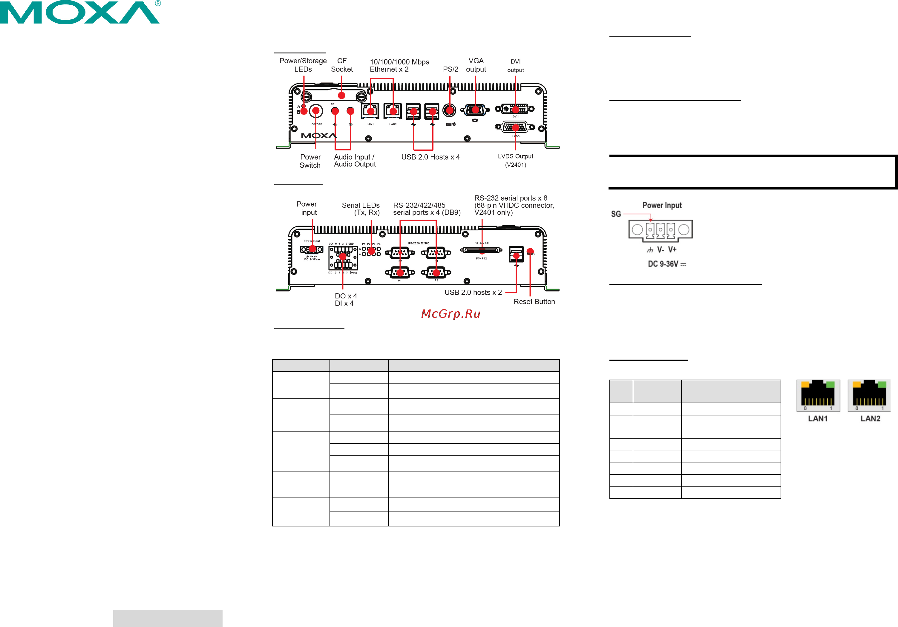
V2401/2402 Panel Layout
The following figures show the panel layouts of the V2401/2402.
Front View
Rear View
LED Indicators
The following table describes the LED indicators located on the
front panel of the V2401/2402.
LED Name LED Color LED Function
Power Green Power is on and functioning normally
Off Power is off or power error exists
Storage Yellow CF/HDD card is detected
Off CF/HDD card is not detected
LAN Green 100 Mbps Ethernet mode
Yellow 1000 Mbps (Gigabit) Ethernet mode
Off No activity or 10 Mbps Ethernet mode
Tx, Tx
(P1-P4)
Green Serial ports P1-P4 transmitting data
Off Serial ports P1-P4 not transmitting data
Rx, Rx
(P1-P4)
Yellow Serial ports P1-P4 receiving data
Off Serial ports P1-P4 not receiving data
Installing the V2401/2402
The V2401/2402 can be DIN-rail mounted, wall mounted and VESA
mounted. Some mounting kits may need to be purchased
separately. Refer to the Hardware User's Manual for detailed
installation instructions.
Connector Description
Power Connector
Connect the 9 to 36 VDC LPS or Class 2 power line to the
V2401/2402’s terminal block. If the power is supplied properly, the
Power LED will light up. The OS is ready when the Ready LED glows
a solid green.
Grounding the V2401/2402
Grounding and wire routing help limit the effects of noise due to
electromagnetic interference (EMI). Run the ground connection
from the ground screw to the grounding surface prior to connecting
the power.
NOTE This product is intended to be mounted to a well-
grounded
mounting surface, such as a metal panel.
SG:
The Shielded Ground (sometimes called
Protected Ground) contact is the right most
of the 3-
pin power terminal block connector
when viewed from the angle shown here.
Connect the SG wire to an appropriate
grounded metal surface.
VGA, DVI and LVDS Outputs
The V2401/2402 comes with a D-Sub 15-pin female connector for
a VGA monitor; it also comes with a DVI-I connector for the DVI
display. The V2401 has even an LVDS interface to connect an LVDS
display. These output interfaces are all located at the front panel.
Use the proper cable to connect.
Ethernet Ports
The 10/100/1000 Mbps Ethernet ports use RJ45 connectors.
Pin 10/100
Mbps
1000 Mbps
1 ETx+ TRD(0)+
2 ETx- TRD(0)-
3 ERx+ TRD(1)+
4 – TRD(2)+
5 – TRD(2)-
6 ERx- TRD(1)-
7 – TRD(3)+
8 – TRD(3)-
Содержание
- Connector description 1
- Ethernet ports 1
- Installing the v2401 2402 1
- Overview 1
- Package checklist 1
- Quick installation guide 1
- Second edition march 2011 1
- V2401 2402 1
- V2401 2402 panel layout 1
- Vga dvi and lvds outputs 1
- Attention 2
- Configuring the ethernet interface 2
- Connecting the v2401 2402 to a pc 2
- Ifdown a disable lan1 lan2 interface first before you reconfigure the lan settings lan1 eth0 lan2 eth1 vi etc network interfaces check the lan interface first 2
- Powering on the v2401 2402 2
- Sync ifup a 2
Похожие устройства
- Moxa V2401-LX Инструкция по эксплуатации
- Moxa V2401-LX Руководство по программной части (Windows)
- Moxa V2401-LX Руководство по программной части (Linux)
- Moxa V2401-LX Руководство по быстрой установке
- Moxa V2401-LX Технические характеристики
- Moxa V2401-XPE Инструкция по эксплуатации
- Moxa V2401-XPE Руководство по программной части (Windows)
- Moxa V2401-XPE Руководство по программной части (Linux)
- Moxa V2401-XPE Руководство по быстрой установке
- Moxa V2401-XPE Технические характеристики
- Moxa V2402-CE Инструкция по эксплуатации
- Moxa V2402-CE Руководство по программной части (Windows)
- Moxa V2402-CE Руководство по программной части (Linux)
- Moxa V2402-CE Руководство по быстрой установке
- Moxa V2402-CE Технические характеристики
- Moxa V2402-LX Инструкция по эксплуатации
- Moxa V2402-LX Руководство по программной части (Windows)
- Moxa V2402-LX Руководство по программной части (Linux)
- Moxa V2402-LX Технические характеристики
- Moxa V2402-LX Руководство по быстрой установке