![Citizen CL-E720 — настройки режима работы принтера: изменение значений меню [36/90]](/img/pdf.png)
Citizen CL-E720 — настройки режима работы принтера: изменение значений меню [36/90]
![Citizen CL-E720 [36/90] Example of changing a menu](/views2/1204394/page36/bg24.png)
36
Chapter 2 Printer Operation
Mode Settings
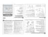
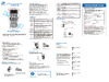
Example of changing a menu
This is an explanation of the method of changing the set value of print
darkness from “10” to “12” in a case where the main menu is “Page Setup”
and the sub menu is “Print Darkness”.
1. Entering Menu Setup Mode.
Ensure LCD displays “Ready”. Then press the MENU key to
enter ‘menu setup mode’ where the printers settings can be
changed or conrmed.
MENU
CL-E720
Ready
The current main menu is displayed.
The following are the functions of each key.
MENU key: displays the previous menu item
Feed key (
): displays the next menu item
Stop key (): enters the Page Setup menu
Pause key (): enters the Save Settings section
Main Menu
Page Setup
1
2
1
2
3
4
4 3
<Main menu item ow>
Displays/changes Page Setup
Displays/changes System Setup
Displays/changes After-Print Action Setup
Displays/changes Interface Setup
Displays machine information
Displays/changes set numbers
Page Setup
Global Cong
System Setup
After Print
Machine Info
Test ModeTest mode
Interface
Displays/changes of Option Inter
face Setup
Option Interface
Press MENU key
Press MENU keyPress Feed key
Press Feed key
Press Feed key
Содержание
- Cl e700 series p.1
- Chapter 1 setup p.2
- Contents p.2
- Chapter 3 printer adjustments p.2
- Chapter 2 printer operation p.2
- Appendixes p.2
- Main features p.3
- Introduction p.3
- Before operation p.3
- Optimal ribbon tension through arcp p.3
- Gs mark statement p.5
- Fcc compliance statement for american users p.5
- Compliance statementfor european users p.5
- Compliance statement for european users p.5
- Etat de conformite emi a l usage des utilisateurs canadiens p.6
- Emi compliance statement for canadian users p.6
- Important safety instructions p.7
- Visit the following site to get documentation drivers utilities and other information http www citizen systems co jp english support index html p.8
- Notice p.8
- Which must be strictly observed p.9
- Warning warning p.9
- Warning p.9
- Safety instructions p.9
- Caution caution p.9
- Caution p.10
- Precautions when installing the printer p.10
- General precautions p.10
- Note the empty carton and packing materials should be stored for future shipping of the printer p.11
- Confirmation of carton contents p.11
- Check that the following accessories are included with the printer in the carton p.11
- Chapter 1 setup p.11
- Confirmation of carton contents p.12
- Chapter 1 setup p.12
- Caution p.12
- Part names and functions p.13
- Front view p.13
- Chapter 1 setup p.13
- Inside the printer p.14
- Chapter 1 setup p.14
- Chapter 1 setup p.15
- Chapter 1 setup p.16
- Chapter 1 setup p.17
- Operation panel p.18
- Chapter 1 setup p.18
- Rear view p.19
- Chapter 1 setup p.19
- Insert the plug of the power cord in the ac outlet p.20
- Driver installation p.20
- Connection to power p.20
- Connect the connector of the power cord to the power cord inlet on the printer p.20
- Check that the power switch to the printer is turned off p.20
- Chapter 1 setup p.20
- Caution p.20
- Connect the other end of the interface cable to the interface connector on the computer and secure it with locks or locking screws where available p.21
- Connect one end of the interface cable to the interface connector on the back of the printer and secure it with locks or locking screws where available p.21
- Chapter 1 setup p.21
- Caution p.21
- Turn off both power switches of the printer and the computer p.21
- Connection to a computer p.21
- Power on off p.22
- Chapter 2 printer operation p.22
- Stop key it stops printing and cancels the alarm p.23
- Pause key temporarily pauses printing p.23
- Normal operating mode p.23
- Menu key p.23
- Feed key feeds media p.23
- Chapter 2 printer operation p.23
- Table of alarm and error indications p.24
- Normal operating mode p.24
- Led functions p.24
- In addition to normal operating mode when an abnormal condition is detected in the printer an alarm sounds and the led lights up red to indicate the type of error the lcd indicates the error message p.24
- Chapter 2 printer operation p.24
- Chapter 2 printer operation p.25
- The position of label and tag media is sensed by either a transparent sensor or a reflective sensor transparent sensor detects the gaps between label media and notches of tag media reflective sensor detects the black mark p.25
- Setting the media p.25
- Menu setting table p 1 p.25
- Media sizes p.25
- Installing the media p.26
- Chapter 2 printer operation p.26
- The path of the media varies according to the orientation of the printing surface set the media according to the diagram shown below p.27
- Setting the media p.27
- Chapter 2 printer operation p.27
- Setting the media p.28
- Setting sensor positions p.28
- Sensor selection method transparent reflective p 5 p.28
- Chapter 2 printer operation p.28
- Adjusting the transparent sensor p 6 p.28
- Adjusting the reflective sensor p 7 p.28
- Chapter 2 printer operation p.29
- Setting the ribbon p.30
- Setting method p.30
- Place the attached ribbon and paper core separately on one of the two attached ribbon holders insert the two ribbon holders into the ribbon and paper cores ensuring that they are pushed in all the way p.30
- Chapter 2 printer operation p.30
- Chapter 2 printer operation p.31
- Chapter 2 printer operation p.32
- When using label media p.33
- When using continuous media p.33
- Operation panel p 8 p.33
- Mode settings p.33
- Hex dump mode p.33
- Chapter 2 printer operation p.33
- Mode settings p.34
- Media width adjustment p 0 p.34
- Media thickness adjustment p 9 p.34
- Chapter 2 printer operation p.34
- When using label media p.34
- When using continuous media p.34
- Setting the media p 5 p.34
- Self print mode p.34
- Stop key enter save p.35
- Pause key exit p.35
- Mode settings p.35
- Menu setup mode p.35
- Menu key shift change p.35
- Functions of the keys p.35
- Feed key shift change p.35
- Chapter 2 printer operation p.35
- Caution p.35
- Entering menu setup mode ensure lcd displays ready then press the menu key to enter menu setup mode where the printers settings can be changed or confirmed p.36
- Chapter 2 printer operation p.36
- After print p.36
- This is an explanation of the method of changing the set value of print darkness from 10 to 12 in a case where the main menu is page setup and the sub menu is print darkness p.36
- Mode settings p.36
- Example of changing a menu p.36
- To change the value of print darkness to 12 press the menu key two times to display 12 on the screen then press the stop key g to temporarily save the value into the printer ram p.37
- Selecting print darkness from the sub menu press the feed key p.37
- One time to display print darkness it is the second item within page setup p.37
- Mode settings p.37
- Entering sub menu press the stop key g the currently set item print speed is displayed p.37
- Displaying the set value of print darkness press the stop key g and the value 10 the currently set value is displayed p.37
- Chapter 2 printer operation p.37
- Save changes to settings unless you save your settings your changes will be lost when you turn off the printer p.38
- Mode settings p.38
- Chapter 2 printer operation p.38
- Mode settings p.39
- Example of changing a menu p 6 p.39
- Chapter 2 printer operation p.39
- You can get a list of the configuration settings in two ways press menu key whilst turning the printer on the led lights up and print settings is displayed on the lcd after printing the printer will enter menu setup mode you can access the configuration print via the test mode print pattern current config from the setup menu p.39
- Printing a list of settings p.39
- Note citizen continually enhances its printers with new options and settings based on our customer s requests extra or changed menu items may appear on the above print out in some cases the set value of option interface is printed even if optional interface is not installed p.39
- The printer can store three sets of configuration settings that can be recalled quickly and easily each config set 1 2 or 3 can contain completely different configuration settings for all menu parameters for example config set 1 could be configured for 6 ips print speed print darkness 10 config set 2 next could be 5 ips continuous card media with black mark print darkness 12 the ability of having three sets of settings is ideal for someone who prints on different media types regularly for example in a label printing bureau global config settings can be printed using the test mode print pattern global config menu option it will also display the currently active config set p.40
- Mode settings p.40
- Global menu settings p.40
- Global configuration sets p.40
- Chapter 2 printer operation p.40
- Top menu sub menu default menu remarks p.41
- Press the menu key in print possible status to enter menu setup mode use the keys on the operation panel according to the lcd display to setup the printer the contents that can be setup on the printer are shown below and the items that are actually displayed on the lcd are shown in p.41
- Page setup menu allows you to change settings related to the media or print quality system setup menu allows you to change settings for the printer hardware and basic control systems after print menu changes how the printer reacts after the label has been printed interfaces changes interface parameters such as baud rate option interfaces communication settings of option interfaces machine information test mode allows you to check and or print test pages and information about the printer global config menu allows you to switch between 3 complete config sets contained within the printer p.41
- Mode settings p.41
- Menu setting table p.41
- For datamax emulation p.41
- Chapter 2 printer operation p.41
- Chapter 2 printer operation p.42
- Top menu sub menu default menu remarks p.42
- Sensor monitor p.42
- Sensor level p.42
- Mode settings datamax emulation p.42
- Top menu sub menu default menu remarks p.43
- Mode settings datamax emulation p.43
- Chapter 2 printer operation p.43
- Top menu sub menu default menu remarks p.44
- Mode settings datamax emulation p.44
- Chapter 2 printer operation p.44
- Top menu sub menu default menu remarks p.45
- Mode settings datamax emulation p.45
- Chapter 2 printer operation p.45
- Top menu sub menu default menu remarks p.46
- Mode settings datamax emulation p.46
- Chapter 2 printer operation p.46
- Top menu sub menu default menu remarks p.47
- Sensor monitor p.47
- Sensor level p.47
- Page setup p.47
- Mode settings p.47
- For zebra emulation p.47
- Chapter 2 printer operation p.47
- Top menu sub menu default menu remarks p.48
- Mode settings zebra emulation p.48
- Chapter 2 printer operation p.48
- Top menu sub menu default menu remarks p.49
- Mode settings zebra emulation p.49
- Chapter 2 printer operation p.49
- Top menu sub menu default menu remarks p.50
- Mode settings zebra emulation p.50
- Chapter 2 printer operation p.50
- Top menu sub menu default menu remarks p.51
- Mode settings zebra emulation p.51
- Chapter 2 printer operation p.51
- Setting method p.52
- Quick setup of the print method p.52
- Menu setup mode p 5 p.52
- Chapter 2 printer operation p.52
- Caution p.52
- Menu setting table p 1 p.53
- Emulation auto detect cross emulation tm p.53
- Emulation auto detect cross emulation p.53
- Chapter 2 printer operation p.53
- Emulation auto detect cross emulation p.54
- Chapter 2 printer operation p.54
- Chapter 3 printer adjustments p.55
- After sensor cal mode lights up release the keys to change the printer to sensor adjustment setting mode p.55
- Turn on the power while pushing the pause key feed key and stop key simultaneously p.55
- Sensor selection method transparent reflective p.55
- Sensor adjustments p.55
- Entering sensor adjustment mode p.55
- Chapter 3 printer adjustments p.56
- Adjusting the transparent sensor p.56
- With the reflective sensor selected install the label media so that it is between the platen roller and the media sensor be careful that black mark and media gap do not pass the media sensor p.57
- The reflective sensor is selected p.57
- Sensor adjustments p.57
- Installing the media p 6 sensor selection method transparent reflective p 5 p.57
- Chapter 3 printer adjustments p.57
- Adjusting the reflective sensor p.57
- Chapter 3 printer adjustments p.58
- Media thickness adjustment p.59
- Installing the media p 6 p.59
- Chapter 3 printer adjustments p.59
- When using thicker media tags card etc p.59
- When using standard label media high quality media or direct thermal media p.59
- Self print mode p 4 p.59
- When using narrow media be sure to make this adjustment if you do not the head may be damaged by jamming etc p.60
- The head pressure varies according to the width of the media being printed the head pressure balance must be adjusted according to media width so that constant head pressure is applied to the head with this printer it can be adjusted easily by turning the media width adjustment dial if the printing is blurred or lightly printed on one side or the media moves in a zigzag pattern adjust the head pressure balance after making an adjustment confirm the output quality with a test print p.60
- The following values are criteria dial adjustment may be required depending on the thickness of print and occurrence of ribbon wrinkles p.60
- Self print mode p 4 p.60
- Media width adjustment p.60
- Installing the media p 6 p.60
- Chapter 3 printer adjustments p.60
- Caution p.60
- Setting the ribbon p 0 p.61
- Ribbon tension adjustment p.61
- Chapter 3 printer adjustments p.61
- Adjustment in the winding side front side p.61
- Adjusting the ribbon p.61
- Self print mode p 4 p.62
- Confirmation of printing after adjustment p.62
- Chapter 3 printer adjustments p.62
- After adjustment perform a test printing again and confirm that there are no wrinkles on the ribbon p.62
- Adjustment in the feeding side rear side p.62
- Adjusting the ribbon p.62
- Ribbon balance adjustment p.63
- Chapter 3 printer adjustments p.63
- Make adjustment according to the position at which looses occur in the ribbon by using the following procedure p.64
- Chapter 3 printer adjustments p.64
- Adjusting the ribbon p.64
- Loosen the screw on the ribbon guide adjusting cam p.65
- Loosen the ribbon guide fixing screws 2 places p.65
- Chapter 3 printer adjustments p.65
- Change the inclination of the ribbon guide by sliding the ribbon guide adjustment cam p.65
- Adjusting the ribbon p.65
- Ribbon guide adjustment p.65
- Perform print and confirm that there are no wrinkles if there are wrinkles make adjustments again p.66
- Once the angle is appropriate tighten all the screws that were loosened p.66
- Media width adjustment p 0 media thickness adjustment p 9 p.66
- Chapter 3 printer adjustments p.66
- Adjusting the ribbon p.66
- Cleaning p.67
- Chapter 3 printer adjustments p.67
- Caution p.67
- Troubleshooting p.68
- Items to check when a malfunction occurs p.68
- Appendixes p.68
- Media width adjustment p 0 p.69
- Media thickness adjustment p 9 p.69
- Cleaning p 7 p.69
- Appendixes p.69
- Troubleshooting p.69
- Setting the ribbon p 0 p.69
- Setting the media p 5 setting the ribbon p 0 p.69
- Menu setting table p 1 p.69
- Troubleshooting p.70
- Setting the ribbon p 0 p.70
- Ribbon tension adjustment p 1 p.70
- Ribbon balance adjustment p 3 p.70
- Menu setting table p 1 p.70
- Led functions p 4 p.70
- Installing the media p 6 setting the ribbon p 0 p.70
- Cleaning p 7 p.70
- Appendixes p.70
- Specifications p.71
- Appendixes p.71
- Appendixes p.72
- Specifications p.72
- Specifications p.73
- Appendixes p.73
- Specifications p.74
- Appendixes p.74
- Usb interface p.75
- This printer is connected to a computer and prints according to commands sent from the computer there are two methods of interface with a computer and it can be connected to any equipment that supports these methods you can also connect to the computer with serial parallel and wireless lan p.75
- Specifications p.75
- Signal line and pin arrangement p.75
- Interfaces p.75
- Appendixes p.75
- Interfaces p.76
- Http server p.76
- Ethernet interface p.76
- By snmp agent function p.76
- Appendixes p.76
- Support protocol p.76
- Snmp agent p.76
- Settings of printer unit and network are done by linkserver web interface for details see linkserver web interface configuration p.76
- Raw socket port p.76
- Perform two way communication of print data and printer status p.76
- Ip address is automatically obtained from dhcp server within 60 seconds after power is connected if the address cannot be obtained automatically fixed ip address default value 169 54 0 is applied p.76
- The indications by led are given below p.77
- Note please do not insert the usb cable by mistake doing so may damage the cable and connector p.77
- Network status display p.77
- Network communication speed display p.77
- Interfaces p.77
- Function of led p.77
- Connecting the connector p.77
- Compatible connectors printer rj 45 connector p.77
- Appendixes p.77
- Appendixes p.78
- The integral linkserver web configuration interface can be used to adjust settings of the printer and its interfaces p.78
- Linkserver web interface configuration p.78
- Interfaces p.78
- Interfaces p.79
- Appendixes p.79
- Interfaces p.80
- Appendixes p.80
- Screen and url in linkserver p.81
- Note the operation of linkserver has been verified in internet explorer 10 11 and google chrome 21 p.81
- Interfaces p.81
- Appendixes p.81
- Signal line and pin arrangement p.82
- Serial interface option p.82
- Serial interface p.82
- Interfaces p.82
- Appendixes p.82
- Specifications p.82
- Respective functions of the switches are as follows p.83
- Interfaces p.83
- Dip switch p.83
- Communication conditions settings can be changed by using the dip switch available on the interface board p.83
- Baud rate selection p.83
- Appendixes p.83
- Requirements to output the x off code p.84
- Xon xoff protocol p.84
- Requirements to output x on code p.84
- Interfaces p.84
- Dtr protocol p.84
- Conditions when the dtr signal is ready high p.84
- Conditions when dtr signal is busy low p.84
- Appendixes p.84
- Appendixes p.85
- Specifications p.85
- Signal line and pin assignment table p.85
- Parallel interface option p.85
- Parallel interface p.85
- Interfaces p.85
- Note busy rises when strobe signal starts and data is latched with strobe signal starts p.86
- Parallel port status signals when an error occurs p.86
- While receiving data p.86
- When power is on time it goes off line p.86
- The status of a signal line will not be changed in bi directional mode such as nibble or ecp mode p.86
- Interfaces p.86
- Compatible timing specification p.86
- Appendixes p.86
- Interfaces p.87
- Center ack p.87
- Appendixes p.87
- While receiving init signal p.87
- Relation of the timing of the busy signal and the ack signal p.87
- Note if the init signal does not have width of 10 to 15μsec or more it cannot act as an init signal if it is lower the init signal is ignored busy starts up when the init signal is perceived p.87
- Replacing the interface board p.88
- Replacement method p.88
- Remove the screws 2 nos that the fixing the interface cover p.88
- Insert the interface port into the slot and connect to the interface connector inside the printer p.88
- Caution p.88
- Appendixes p.88
- Replacing the interface board p.89
- Fix the interface port to the printer by using the removed screw 2 nos p.89
- Appendixes p.89
Похожие устройства
-
 Citizen CL-E720Command Reference DMX
 -
 Citizen CL-E720Утилита для печати этикеток
 -
 Citizen CL-E720Command Reference ZPL
 -
 Citizen CL-E720Autocutter
 -
 Citizen CL-E720Сетевые карты
 -
 Citizen CL-S700Описание системы команд
 -
 Citizen CL-S700Краткая инструкция
 -
 Citizen CL-S700Руководство пользователя
 -
 Citizen CL-S700Брошюра
 -
 Citizen CL-E720Брошюра
 -
 Epson P-1000LWИнструкция по монтажу
 -
 Puty PT100ECH, русский/английский, для печати на лентах Vell CHИнструкция
Узнайте, как изменить настройки яркости печати на принтере. Пошаговая инструкция по входу в меню и изменению параметров для оптимизации работы устройства.