
Asus V8-P8H67E Инструкция по эксплуатации онлайн


Содержание
- Second edition march 2011 2
- Chapter 1 system introduction 3
- Chapter 2 starting up 3
- Chapter 3 motherboard info 3
- Table of contents 3
- Chapter 4 bios setup 4
- Table of contents 4
- Table of contents 5
- Canadian department of communications statement 6
- Federal communications commission statement 6
- Notices 6
- Class 1 laser product 7
- Electrical safety 7
- Operation safety 7
- Safety information 7
- About this guide 8
- Audience 8
- Conventions used in this guide 8
- How this guide is organized 8
- Where to find more information 8
- Check your v series p8h67e system package for the following items 9
- If any of the items is damaged or missing contact your retailer immediately 9
- System package contents 9
- Chapter 1 11
- System introduction 11
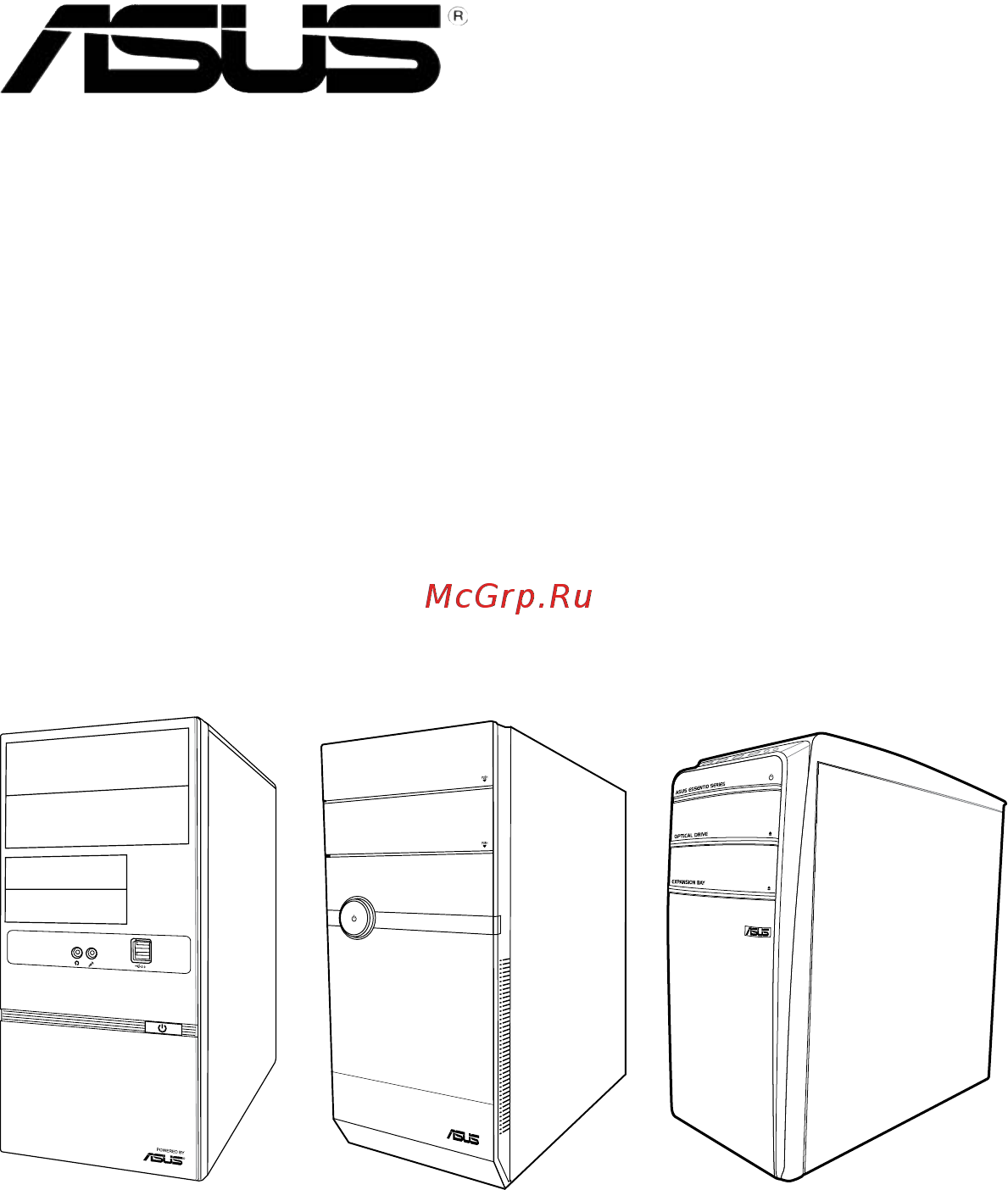
- Front panel 12
- V6 p8h67e front panel 12
- Welcome 12
- V7 p8h67e front panel 13
- V9 v8 p8h67e front panel 14
- Rear panel 15
- 7 asus v series p8h67e 17
- Act link 17
- Audio 2 4 6 or 8 channel configuration 17
- Chassis fan vent this vent is for the fan that provides ventilation inside the system chassis 17
- Expansion slot covers remove these covers when installing expansion cards 17
- Lan port 17
- Lan port led indications 17
- Lan rj 45 port this port allows gigabit connection to a local area network lan through a network hub refer to the table below for the lan port led indications 17
- Optical s pdif out port this port connects an external audio output device via an optical s pdif cable 17
- Power supply unit fan vent this vent is for the psu fan that provides ventilation inside the power supply unit 17
- Power switch this switch is for switching on off the power supply unit 17
- Video graphics adapter vga port this 15 pin port is for a vga monitor or other vga compatible devices 17
- Voltage selector 18
- Internal components 19
- 10 chapter 1 system introduction 20
- Continued on the next page 20
- Ddr3 1333 mhz capability 20
- Qualifiedvendorslists qvl 20
- 11 asus v series p8h67e 21
- Ddr3 1333 mhz capability 21
- 12 chapter 1 system introduction 22
- A one 1 module inserted into any slot as single channel memory configuration we 22
- B two 2 modules inserted into either the blue slots or the black slots as one pair of 22
- C four 4 modules inserted into both the blue slots and the black slots as two pairs of 22
- Ddr3 1066mhz capability 22
- Dimm support 22
- Dual channel memory configuration 22
- Dual channel memory configuration we suggest that you install the modules into slots a2 and b2 for better compatibility 22
- Ss single sided ds double sided 22
- Suggest that you install the module into a2 slot 22
- Visit the asus website at www asus com for the latest qvls 22
- Chapter 2 23
- Starting up 23
- Installing an operating system 24
- Powering up 24
- Press the system power button to enter the os 24
- Support dvd information 24
- The barebone system supports window 24
- The support dvd that came with the system contains useful software and several utility drivers that enhance the system features 24
- Xp vista 7 operating systems os always install the latest os version and corresponding updates so you can maximize the features of your hardware 24
- Asus install 25
- Browser configuration utility 25
- Intel chipset driver 25
- Intel graphics accelerator driver 25
- Management engine interface 25
- Reaktek audio driver 25
- Realtek lan driver 25
- Running the support dvd 25
- Usb 3 driver 25
- Adobe reader 9 26
- Asus ai manager 26
- Asus ai suite ii 26
- Asus install 26
- Internet radio 26
- Pc cillin 2010 26
- Realtek ethernet utility 26
- Utilities menu 26
- Make disk menu 27
- Manual menu 27
- Asus contact information 28
- Motherboard info 28
- Other information 28
- Browse this dvd 29
- Filelist 29
- Ai suite ii 30
- Installing ai suite ii 30
- Software information 30
- Using ai suite ii 30
- Probe ii 32
- Sensor recorder 33
- Cpu frequency 34
- Monitor 34
- Sensor 34
- Asus update 35
- Update 35
- Updating the bios through the internet 35
- Updating the bios through a bios file 36
- System information 37
- Settings 38
- Asus ai manager 39
- Installing ai manager 39
- Launching ai manager 39
- Ai disk allows you to easily clear temporary ie files ie cookies ie urls ie history or the recycle bin click the ai disk icon on the quick bar to display the full ai disk window and select the items you want to clear click apply when done 40
- Ai manager quick bar 40
- Ai security enables you to set a password to secure your devices such as usb flash disks and cd dvd disks from unauthorized access 41
- To change password 41
- To lock a device to lock a device 41
- To unlock the selected device 41
- Ai booting allows you to specify the boot device priority sequence 42
- My favorites 42
- To add an application 42
- To specify the boot sequence to specify the boot sequence 42
- Information 43
- Support 43
- Chapter 3 45
- Motherboard info 45
- 2 chapter 3 motherboard info 46
- Introduction 46
- Motherboard layout 46
- P8h67 m pro 46
- The vintage v series p8h67e barebone system comes with an asus motherboard this chapter provides technical information about the motherboard for future upgrades or system reconfiguration 46
- Jumper 47
- P8h67 m pro clear rtc ram 47
- 4 chapter 3 motherboard info 48
- Connectors 48
- Ich7 serial ata connectors 7 pin sata1 sata2 sata3 sata4 48
- Install the window 48
- Never connect a 1394 cable to the usb connectors doing so will damage the motherboard 48
- P8h67 m pro sata connectors 48
- P8h67 m pro usb2 connectors 48
- The usb module is purchased separately 48
- These connectors are for the serial ata signal cables for serial ata hard disk drives 48
- These connectors are for usb 2 ports connect the usb module cable to any of these connectors are for usb 2 ports connect the usb module cable to any of these connectors then install the module to a slot opening at the back of the system chassis these usb connectors comply with usb 2 specification that supports up to 480 mbps connection speed 48
- Usb connectors 10 1 pin usb56 usb78 usb910 48
- Xp service pack 2 or later version before using serial ata 48
- Connect the fan cables to the fan connectors on the motherboard ensuring that the connect the fan cables to the fan connectors on the motherboard ensuring that the black wire of each cable matches the ground pin of the connector 49
- Cpu chassis and power fan connectors 4 pin cpu_fan 3 pin cha_fan 3 pin pwr_fan 49
- P8h67 m pro fan connectors 49
- 6 chapter 3 motherboard info 50
- By default this connector is set to hd audio if you want to connect a high definition 50
- Connector to avail of the motherboard s high definition audio capability 50
- Digital audio connector 4 1 pin spdif_out 50
- Front panel audio connector 10 1 pin aafp 50
- Front panel audio module to this connector set the hd audio controller item in the bios to enabled see section 4 onboard devices configuration for details 50
- P8h67 m pro analog front panel connector 50
- P8h67 m pro digital audio connector 50
- The s pdif out module is purchased separately 50
- This connector is for a chassis mounted front panel audio i o module that supports either this connector is for a chassis mounted front panel audio i o module that supports either hd audio or legacy ac 97 audio standard 50
- This connector is for the s pdif audio module to allow digital sound output connect this connector is for the s pdif audio module to allow digital sound output connect one end of the s pdif audio cable to this connector and the other end to the s pdif module 50
- We recommend that you connect a high definition front panel audio module to this 50
- 7 asus v series p8h67e 51
- Atx power connectors 24 pin eatxpwr 8 pin atx12v 51
- Do not forget to connect the 4 pin atx12v power plug otherwise the system will not 51
- Eatx12v 51
- Eatxpwr 51
- F you are uncertain about the minimum power supply requirement for your system 51
- If you intend to use a psu with 20 pin and 4 pin power plugs make sure that the 20 pin 51
- P8h67 m pro atx power connectors 51
- Power plug can provide at least 15 a on 12 v and that the psu has a minimum power rating of 300 w the system may become unstable or may not boot up if the power is inadequate 51
- Psu with a minimum of 300w power rating this psu type has 24 pin and 4 pin power plugs 51
- Refer to the recommended power supply wattage calculator at http support asus com powersupplycalculator pscalculator aspx slanguage en us for details 51
- System with more power consuming devices or when you intend to install additional devices the system may become unstable or may not boot up if the power is inadequate 51
- These connectors are for atx power supply plugs the power supply plugs are these connectors are for atx power supply plugs the power supply plugs are designed to fit these connectors in only one orientation find the proper orientation and push down firmly until the connectors completely fit 51
- We recommend that you use a psu with higher power output when configuring a 51
- We recommend that you use an atx 12v specification 2 compliant power supply unit 51
- P8h67 m pro system panel connector 52
- Installing dimms that are incompatible with the motherboard may cause system boot failure and the dram_led near the memok switch lights continuously press and hold the memok switch until the dram_led starts blinking to begin automatic memory compatibility tuning for successful boot 53
- Memok switch 53
- P8h67 m pro memok switch 53
- Dram led 54
- P8h67 m pro dram led 54
- Bios setup 55
- Chapter 4 55
- An error message appears on the screen during the system startup and requests you to run the bios setup 56
- Bios basic input and output system stores system settings such as storage device configuration overclocking settings advanced power management and boot device configuration that are needed for system startup in the motherboard cmos in normal circumstances the default bios settings apply to most conditions to ensure optimum performance do not change the default bios settings except in the following circumstances 56
- Managing and updating your bios 56
- You have installed a new system component that requires further bios settings or update 56
- Asus update utility 57
- Installing asus update 57
- Updating the bios 57
- Asus ez flash 2 58
- Asus crashfree bios 3 59
- Recovering the bios 59
- Asus bios updater 60
- Asus v series p8h67e 4 7 61
- Backing up the current bios 61
- Ensure that the usb flash drive is not write protected and has at least 1024kb free space to save the file 61
- Filename extension 61
- The bios updater backup screen appears indicating the bios backup process when bios backup is done press any key to return to the dos prompt 61
- The filename is any user assigned filename with no more than eight alphanumeric the filename is any user assigned filename with no more than eight alphanumeric characters for the filename and three alphanumeric characters for the extension 61
- To backup the current bios file using the bios updater 61
- 8 chapter 4 bios setup 62
- After updating bios 62
- Bios updater checks the selected bios file and prompts you to confirm bios update 62
- Disconnected them 62
- Do not shut down or reset the system while updating the bios to prevent system boot failure 62
- Ensure to connect all sata hard disk drives after updating the bios file if you have 62
- Ensure to load the bios default settings to ensure system compatibility and stability 62
- For bios updater version 1 4 or later the utility automatically exits to the dos prompt 62
- Select the load optimized defaults item under the exit menu refer to section 4 exit menu for details 62
- The bios updater screen appears as below 62
- To exit bios updater restart your computer 62
- To update the bios file using bios updater 62
- Updating the bios file 62
- Bios menu screen 63
- Bios setup program 63
- Entering bios setup after post 63
- Entering bios setup at startup 63
- Post continues with its routines 63
- Press the power button to turn the system off then turn it back on do this option only if you failed to enter bios setup using the first two options 63
- Press the reset button on the system chassis 63
- Simultaneously 63
- The bios setup program can be used under two modes ez mode and advanced mode you can change modes from the exit menu or from the exit advanced mode button in the ez mode advanced mode screen 63
- To enter bios setup after post do any of the following 63
- To enter bios setup at startup 63
- Use the bios setup program to update the bios or configure its parameters the bios screens include navigation keys and brief online help to guide you in using the bios setup program 63
- 10 chapter 4 bios setup 64
- By default the ez mode screen appears when you enter the bios setup program the ez mode provides you an overview of the basic system information and allows you to select the display language system performance mode and boot device priority to access the advanced mode click exit advanced mode then select advanced mode 64
- Displays the cpu motherboard temperature cpu 5v 3 v 12v voltage output cpu chassis power fan speed 64
- Displays the system properties of the selected mode on the right hand side 64
- Efi bios utility ez mode 64
- Exits the bios setup program without saving the changes saves the changes and resets the system or enters the advanced mode 64
- Ez mode 64
- Loads optimized default selects the boot device priority 64
- Normal mode asus optimal mode 64
- Power saving mode 64
- Selects the boot device priority 64
- Selects the display language of the bios setup program 64
- System 64
- The boot device options vary depending on the devices you installed to the system 64
- The boot menu f8 button is available only when the boot device is installed to the 64
- The default screen for entering the bios setup program can be changed refer to the setup mode item in section 4 boot memu for details 64
- Advanced for changing the advanced system settings 65
- Advanced mode 65
- Ai tweaker for changing the overclocking settings 65
- Asus v series p8h67e 4 11 65
- Back button 65
- Boot for changing the system boot configuration 65
- Configuration fields 65
- Exit for selecting the exit options and loading default settings 65
- General help menu bar 65
- Main for changing the basic system configuration 65
- Menu bar 65
- Menu items scroll bar 65
- Monitor for displaying the system temperature power status and changing the fan settings 65
- Navigation keys 65
- Pop up window 65
- The advanced mode provides advanced options for experienced end users to configure the bios settings the figure below shows an example of the advanced mode refer to the following sections for the detailed configurations 65
- The menu bar on top of the screen has the following main items 65
- To access the ez mode click exit then select asus ez mode 65
- Tool for configuring options for special functions 65
- Back button 66
- Configuration fields 66
- General help 66
- Menu items 66
- Navigation keys 66
- Pop up window 66
- Scroll bar 66
- Submenu items 66
- Allows you to choose the bios language version from the options configuration options english 67
- Allows you to set the system date 67
- Allows you to set the system time 67
- Asus v series p8h67e 4 13 67
- If you have forgotten your bios password erase the cmos real time clock rtc 67
- Installed after you set a password these items show installed 67
- Main menu 67
- Ram to clear the bios password see section 3 jumper for information on how to erase the rtc ram 67
- Security 67
- System date day xx xx xxxx 67
- System language english 67
- System time xx xx xx 67
- The administrator or user password items on top of the screen show the default not 67
- The main menu screen appears when you enter the advanced mode of the bios setup program the main menu provides you an overview of the basic system information and allows you to set the system date time language and security settings 67
- The security menu items allow you to change the system security settings 67
- Administrator password 68
- User password 68
- Advanced menu 69
- Cpu configuration 69
- Cpu ratio auto 69
- Disabled disables the cpu thermal monitor function 69
- Enabled enables the overheated cpu to throttle its clock speed to cool down 69
- Intel adaptive thermal monitor enabled 69
- Keys or the numeric keypad to adjust the ratio the valid value ranges vary according to your cpu model 69
- The advanced menu items allow you to change the settings for the cpu and other system devices 69
- The items in this menu show the cpu related information that the bios automatically detects 69
- Active processor cores all 70
- Execute disable bit enabled 70
- Hyper threading enabled 70
- Igpu memory 64m 70
- Igpu multi monitor disabled 70
- Initiate graphic adapter peg pci 70
- Intel r virtualization technology disabled 70
- Limit cpuid maximum disabled 70
- Render standby enabled 70
- System agent configuration 70
- High precision timer enabled 71
- Pch configuration 71
- S m a r t status check enabled 71
- Sata configuration 71
- Sata mode ide mode 71
- Serial ata controller 0 enhanced 71
- Serial ata controller 1 enhanced 71
- Asmedia usb 3 controller enabled 72
- Ehci hand off disabled 72
- Hd audio controller enabled 72
- Legacy usb support enabled 72
- Onboard devices configuration 72
- Reaktek lan controller enabled 72
- Realtek pxe oprom disabled 72
- Usb configuration 72
- Xhci hand off enabeled 72
- Asmedia usb 3 battery charging support enabled 73
- Power on by pci disabled 73
- Power on by pcie disabled 73
- Power on by ps 2 keyboard disabled 73
- Power on by ps 2 mouse disabled 73
- Power on by rtc disabled 73
- Restore ac power loss power off 73
- Wol include ac power loss disabled 73
- 20 chapter 4 bios setup 74
- Cpu chassis power fan speed xxxx rpm or ignore n a 74
- Cpu temperature mb temperature xxxºc xxxºf 74
- Monitor menu 74
- The monitor menu displays the system temperature power status and allows you to change the fan settings 74
- The onboard hardware monitor automatically detects and displays the cpu and motherboard temperatures select ignore if you do not wish to display the detected temperatures 74
- The onboard hardware monitor automatically detects and displays the cpu chassis and power fan speeds in rotations per minute rpm if the fan is not connected to the motherboard the field shows n a select ignore if you do not wish to display the detected speed 74
- Anti surge support enabled 75
- Chassis q fan control enabled 75
- Cpu q fan control enabled 75
- Cpu voltage 3 v voltage 5v voltage 12v voltage 75
- 22 chapter 4 bios setup 76
- Advanced mode sets advanced mode as the default screen for entering the bios setup 76
- Boot menu 76
- Bootup numlock state on 76
- Disabled disables the full screen logo display feature 76
- Enabled enables the full screen logo display feature 76
- Ez mode sets ez mode as the default screen for entering the bios setup program 76
- Force bios the third party rom messages will be forced to display during the boot sequence 76
- Full screen logo enabled 76
- Keep current the third party rom messages will be displayed only if the third party manufacturer had set the add on device to do so 76
- Off sets the power on state of the numlock to off 76
- On sets the power on state of the numlock to on 76
- Option rom messages force bios 76
- Program 76
- Set this item to enabled to use the asus mylogo 2 feature 76
- Setup mode ez mode 76
- The boot menu items allow you to change the system boot options 76
- Asus ez flash 2 77
- Boot option priorities 77
- Boot override 77
- Tools menu 77
- Asus ez mode 78
- Discard changes exit 78
- Exit menu 78
- Launch efi shell from filesystem device 78
- Load optimized defaults 78
- Save changes reset 78
- Asus computer gmbh germany and austria 79
- Asus computer international america 79
- Asus contact information 79
- Asustek computer inc 79
- Eur 0 4 minute from a german fixed landline eur 0 2 minute from a mobile phone 79
- Technical support 79
Похожие устройства
- Asus EEEBOX PC EB1007 Инструкция по эксплуатации
- Asus EEEBOX PC EB1012 Инструкция по эксплуатации
- Asus EEEBOX PC EB1012P Инструкция по эксплуатации
- Asus EEEBOX PC EB1012U Инструкция по эксплуатации
- Asus EEEBOX PC EB1020 Инструкция по эксплуатации
- Asus EEEBOX PC EB1021 Инструкция по эксплуатации
- Asus EEEBOX PC EB1501 Инструкция по эксплуатации
- Asus EEEBOX PC EB1501P Инструкция по эксплуатации
- Asus EEEBOX PC EB1501U Инструкция по эксплуатации
- Asus EEE PC X101CH Инструкция по эксплуатации
- Asus EEE PC X101H Инструкция по эксплуатации
- Asus EEE PC X101 Инструкция по эксплуатации
- Asus EEE PC 1025CE Инструкция по эксплуатации
- Asus EEE PC 1015T Инструкция по эксплуатации
- Asus EEE PC 1015PW Инструкция по эксплуатации
- Asus EEE PC 1015PEM Инструкция по эксплуатации
- Asus EEE PC 1015PED Инструкция по эксплуатации
- Asus EEE PC 1015PE (SEASHELL) Инструкция по эксплуатации
- Asus EEE PC 1015P (SEASHELL) Инструкция по эксплуатации
- Asus EEE PC 1015BX Инструкция по эксплуатации