
Airwell VLR 524 Инструкция по эксплуатации онлайн
English
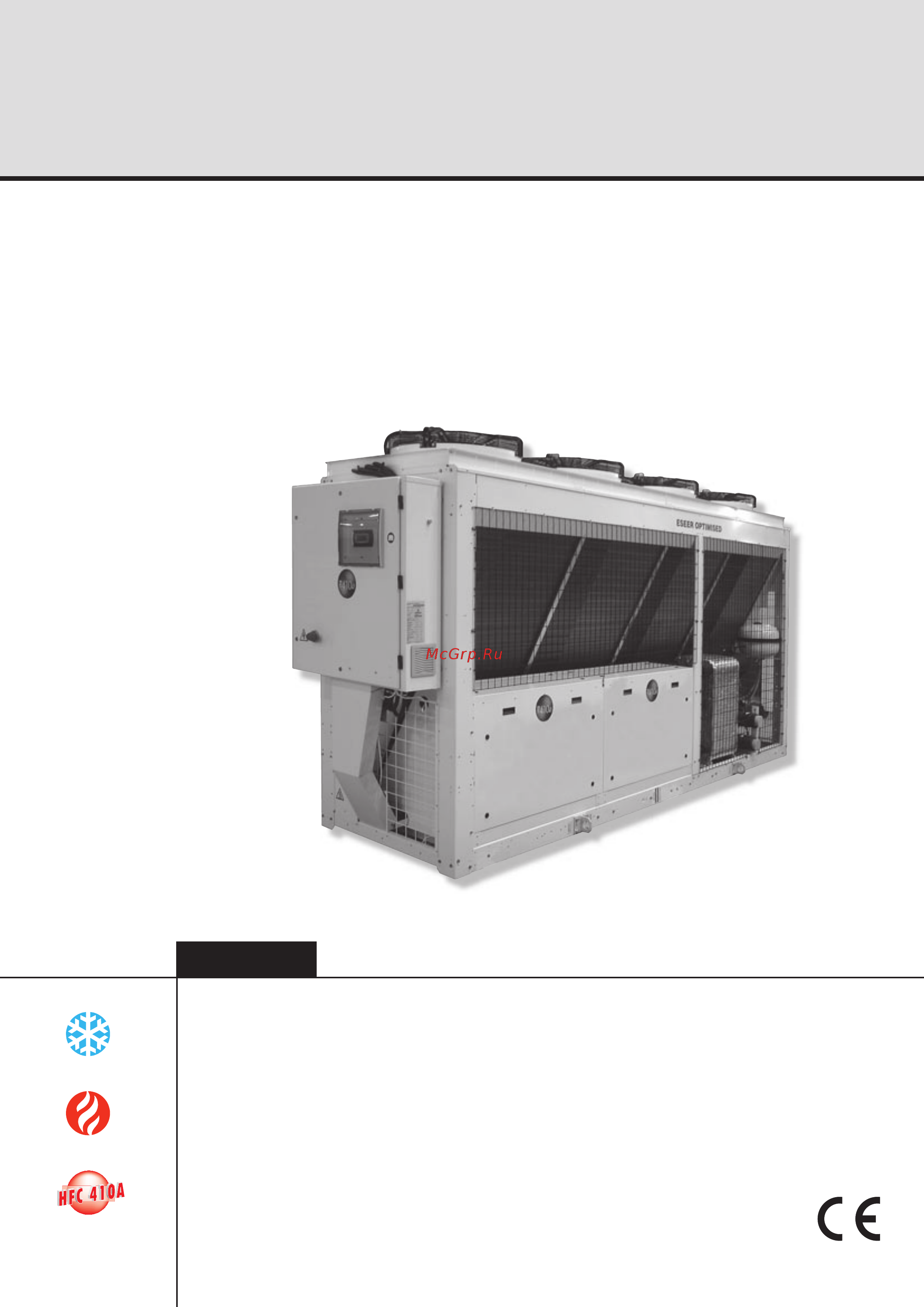
Air cooled water chillers, air cooled condensing units and air-to-water
reverse cycle heat pumps
Installation and maintenance manual
IOM VL410-N.1GB
Date : July 2007
Supersedes : None
VLS / VLC / VLH / VLR
524 ÷ 1204
137
308 kW
150
336 kW
Содержание
- Air cooled water chillers air cooled condensing units and air to water reverse cycle heat pumps 1
- English 1
- Installation and maintenance manual 1
- Iom vl410 n gb 1
- Vls vlc vlh vlr 1
- Control 2
- English 2
- Foreword 2
- General description 2
- Installation 2
- Safety 2
- Start up 2
- Table of contents 2
- Technical data 2
- Transport lifting and positioning 2
- Dismantling demolition and scrapping 3
- Maintenance 3
- Spare parts 3
- Table of contents 3
- Troubleshooting 3
- An introduction to the manual 4
- Emergency stop normal stop 4
- English 4
- Foreword 4
- Introduction 4
- Warranty 4
- Definitions 5
- Foreword 5
- Safety 5
- Access to the unit 6
- English 6
- General precautions 6
- Precautions against residual risks 6
- Safety 6
- Safety 7
- English 8
- Keep lift hook on this line 8
- Safety 8
- Safety labels 8
- Tenere su questa linea gancio di sollevamento 8
- Aus outlet 9
- Ein inlet 9
- Entrée entrata 9
- Safety 9
- Sortie uscita 9
- English 10
- Safety 10
- Safety regulations 10
- Safety 11
- English 12
- Safety 12
- Inspection 13
- Lifting 13
- Transport lifting and positioning 13
- Anchoring 14
- English 14
- Storage 14
- Transport lifting and positioning 14
- Installation 15
- Positioning of the unit 15
- Spring isolator installation 15
- English 16
- External hydraulic circuit 16
- Installation 16
- Draining the defrosting waste water for heat pump unit only 17
- Hydraulic connection 17
- Installation 17
- Installation flow switch 17
- Electrical connections 18
- English 18
- Installation 18
- Power supply 18
- Installation 19
- Vls vlh vlc version electrical connections 19
- English 20
- Installation 20
- Page 19 20
- Vlr version electrical connections 20
- Y morsettiere utente 20
- Connecting plate type evaporator temperature sensors 21
- Forced shuttering 21
- Installation 21
- Temperature sensors 21
- Three way valve 21
- Total heat recovery features 21
- English 22
- Preliminary check 22
- Start up 22
- Checking the operation 23
- Delivery to the customer 23
- Start up 23
- Control 24
- Control of vls vlh vlc with 4 compressors the chiller control system 24
- English 24
- General information 24
- Introduction 24
- Keyboard display terminal 24
- Main characteristics 24
- Terminal key board description 24
- Control 25
- Display 25
- Keyboard 25
- Alarms 26
- Control 26
- English 26
- Page 25 26
- Control 27
- Page 26 27
- Pressing the set key allows you to enter the set point level accessible to the user the parameters that can be set are listed below along with the limit values and the default values standard shop settings 27
- Setpoint 27
- Control 28
- English 28
- Protection and safety equipment 28
- Control 29
- Page 28 29
- Sif version configuration 29
- The table below shows the correspondance between chiller model fan rpm high static pressu re 29
- Units equipped with special inverter fans sif can be set up on the field to give the unit a specific sta tic pressure by entering parameter in service level max speed vdc it is possible to modify high static pressure 29
- Compressors 30
- English 30
- General description 30
- General specifications 30
- Introduction 30
- Refrigeration circuits 30
- Water heat exchanger 30
- Air heat exchanger 31
- Coils are made of copper pipes in staggered rows mechanically expanded inside an aluminium finned pack 31
- Fans are of directly coupling propeller type provi ded with aluminium blade with wing profile each fan is provided with galvanised steel accident prevention guard finally motors are completely closed protection class ip54 protection thermostat immersed in win dings 31
- General description 31
- Page 30 31
- The hydraulic connections to the evaporator are of 2 31
- Victaulic type on 504 804 units and 3 victaulic type on 904 1204 units 31
- Vlh refrigeration diagram 31
- Vls refrigeration diagram 31
- English 32
- General description 32
- Page 31 32
- Vlc refrigeration diagram 32
- Vlr refrigeration diagram 32
- Accessories 33
- Electric power supply and control system 33
- General description 33
- English 34
- Pressure drops 34
- Technical data 34
- 1 indicative value always refer to the value specified on the unit s label high efficiency units hse with inverter fans sif units with high static pressure fans 35
- Page 34 35
- Technical data 35
- 1 indicative value always refer to the value specified on the unit s label high efficiency units hse with inverter fans sif units with high static pressure fans 36
- English 36
- Page 35 36
- Technical data 36
- 1 indicative value always refer to the value specified on the unit s label high efficiency units hse with inverter fans 37
- Page 36 37
- Technical data 37
- 1 indicative value always refer to the value specified on the unit s label high efficiency units hse with inverter fans 38
- English 38
- Page 37 38
- Technical data 38
- 1 indicative value always refer to the value specified on the unit s label high efficiency units hse with inverter fans 39
- Page 38 39
- Technical data 39
- 1 indicative value always refer to the value specified on the unit s label high efficiency units hse with inverter fans 40
- English 40
- Page 39 40
- Technical data 40
- 1 indicative value always refer to the value specified on the unit s label 41
- Page 40 41
- Technical data 41
- 1 indicative value always refer to the value specified on the unit s label 42
- English 42
- Page 41 42
- Technical data 42
- 1 indicative value always refer to the value specified on the unit s label high efficiency units hse with inverter fans sif units with high static pressure fans 43
- Page 42 43
- Technical data 43
- 1 indicative value always refer to the value specified on the unit s label high efficiency units hse with inverter fans sif units with high static pressure fans 44
- English 44
- Page 43 44
- Technical data 44
- 1 indicative value always refer to the value specified on the unit s label high efficiency units hse with inverter fans 45
- Page 44 45
- Technical data 45
- 1 indicative value always refer to the value specified on the unit s label high efficiency units hse with inverter fans 46
- English 46
- Page 45 46
- Technical data 46
- 1 indicative value always refer to the value specified on the unit s label high efficiency units hse with inverter fans 47
- Page 46 47
- Technical data 47
- 1 indicative value always refer to the value specified on the unit s label high efficiency units hse with inverter fans 48
- English 48
- Page 47 48
- Technical data 48
- 1 indicative value always refer to the value specified on the unit s label 49
- Page 48 49
- Technical data 49
- 1 indicative value always refer to the value specified on the unit s label 50
- English 50
- Page 49 50
- Technical data 50
- High efficiency units hse with inverter fans sif units with high static pressure fans 51
- Page 50 51
- Technical data 51
- English 52
- High efficiency units hse with inverter fans sif units with high static pressure fans 52
- Page 51 52
- Technical data 52
- High efficiency units hse with inverter fans 53
- Page 52 53
- Technical data 53
- English 54
- High efficiency units hse with inverter fans 54
- Page 53 54
- Technical data 54
- High efficiency units hse with inverter fans 55
- Page 54 55
- Technical data 55
- English 56
- High efficiency units hse with inverter fans 56
- Page 55 56
- Technical data 56
- Page 56 57
- Technical data 57
- English 58
- Page 57 58
- Technical data 58
- 1 indicative value always refer to the value specified on the unit s label high efficiency units hse with inverter fans sif units with high static pressure fans 59
- Page 58 59
- Technical data 59
- 1 indicative value always refer to the value specified on the unit s label high efficiency units hse with inverter fans sif units with high static pressure fans 60
- English 60
- Page 59 60
- Technical data 60
- Page 60 61
- Technical data 61
- Unit electrical data 61
- English 62
- Page 61 62
- Technical data 62
- Compressors electrical data 63
- Page 62 63
- Technical data 63
- English 64
- Fans electrical data 64
- Page 63 64
- Technical data 64
- Page 64 65
- Position of shock absorbers and weight distribution on supports 65
- Technical data 65
- Vlc 524 604 al cu bln ln eln ht version 65
- Vlh 524 604 al cu bln ln eln ht version 65
- Vlr 524 604 al cu bln ln eln ht version 65
- Vls 524 604 al cu bln ln eln ht version 65
- Vls vlh vlc 524 604 bln ln eln ht version 65
- Dimensions are referred to unit with antivibration mounted isolators 66
- English 66
- Page 65 66
- Technical data 66
- Vlc 524 604 cu cu bln ln eln ht version 66
- Vlh 524 604 cu cu bln ln eln ht version 66
- Vlr 524 604 cu cu bln ln eln ht version 66
- Vls 524 604 cu cu bln ln eln ht version 66
- Dimensions are referred to unit with antivibration mounted isolators 67
- Page 66 67
- Technical data 67
- Vlc 704 1204 al cu bln ln eln ht version 67
- Vlh 704 1204 al cu bln ln eln ht version 67
- Vls 704 1204 al cu bln ln eln ht version 67
- Vls vlh vlc 704 1204 bln ln eln ht version 67
- Dimensions are referred to unit with antivibration mounted isolators 68
- English 68
- Page 67 68
- Technical data 68
- Vlc 704 1204 cu cu bln ln eln ht version 68
- Vlh 704 1204 cu cu bln ln eln ht version 68
- Vlr 704 1204 al cu bln ln eln ht version 68
- Vlr 704 1204 cu cu bln ln eln ht version 68
- Vls 704 1204 cu cu bln ln eln ht version 68
- Overall dimensions 69
- Technical data 69
- Vls vlh 524 604 bln ln eln ht 69
- 804 904 1204 70
- English 70
- Technical data 70
- Vls vlh 704 1204 bln ln eln ht 70
- Page 70 71
- Technical data 71
- Vlc 524 604 bln ln eln ht 71
- Vls eng qxp 12 04 2007 14 43 pagina 70 71
- English 72
- Page 71 72
- Technical data 72
- Vlc 704 1204 bln ln eln ht 72
- Page 72 73
- Technical data 73
- Vlr 524 604 bln ln eln ht 73
- Water connections 73
- 804 904 1204 74
- English 74
- Page 73 74
- Technical data 74
- Vlr 704 1204 bln ln eln ht 74
- Page 74 75
- Technical data 75
- Vls vlh 524 604 with hydrokit 75
- Water connections 75
- 804 904 1204 76
- English 76
- Page 75 76
- Technical data 76
- Vls vlh 704 1204 with hydrokit 76
- Installation of several units 77
- Installation of single units 77
- Page 76 77
- Service spaces 77
- Technical data 77
- Vls vlc vlh vlr all models 77
- English 78
- General requirements 78
- Maintenance 78
- Planned maintenance 78
- Compressor 79
- Condenser 79
- Maintenance 79
- Refrigerant charge 79
- Dehydrating filter 80
- English 80
- Evaporator 80
- Maintenance 80
- Sight glass 80
- Thermostatic expansion valve 80
- Troubleshooting 81
- English 82
- Troubleshooting 82
- Oil for compressors 83
- Spare part list 83
- Spare parts 83
- Wiring diagrams 83
- Dismantling demolition and scrapping 84
- English 84
- Generalities 84
- Itelco industry 85
Похожие устройства
- Airwell VLR 524 Техническое описание
- Airwell VLR 524 Инструкция по эксплуатации
- Airwell VLR 604 Инструкция по эксплуатации
- Airwell VLR 604 Техническое описание
- Airwell VLR 604 Инструкция по эксплуатации
- Airwell VLR 704 Инструкция по эксплуатации
- Airwell VLR 704 Техническое описание
- Airwell VLR 704 Инструкция по эксплуатации
- Airwell VLR 804 Инструкция по эксплуатации
- Airwell VLR 804 Техническое описание
- Airwell VLR 804 Инструкция по монтажу
- Airwell VLR 904 Инструкция по эксплуатации
- Airwell VLR 904 Техническое описание
- Airwell VLR 904 Инструкция по монтажу
- Airwell VLR 1004 Инструкция по эксплуатации
- Airwell VLR 1004 Техническое описание
- Airwell VLR 1004 Инструкция по монтажу
- Airwell VLR 1104 Инструкция по эксплуатации
- Airwell VLR 1104 Техническое описание
- Airwell VLR 1104 Инструкция по монтажу