![D-Link DGS-1210-12TS/ME [110/159] Security access authentication control login method lists](/img/pdf.png)
D-Link DGS-1210-12TS/ME [110/159] Security access authentication control login method lists
Содержание
- D link 1
- Dgs 1 2 1 о м e series 1
- Table of contents 2
- Table of contents 3
- Table of contents 4
- Table of contents 5
- Table of contents 6
- Table of contents 7
- About this guide 8
- Copyright and trademarks 8
- Copyright and trademarks_________________________________________________________ 8
- Terms usage 8
- 12ts 20 28x 28xs 52 me only 9
- Connecting the dps 200a 500a 500dc to the rps port for dgs 1210 9
- Front panel description 9
- Front panel description____________________________________ 9
- Installing the rps into the rack mount chassis for dgs 1210 10 12ts 20 28x 28xs 52 me only 9
- Product introduction 9
- Side panel description 9
- Switch description 9
- Switch description front panel description led indicators rear panel description 9
- Switch description________________________________________________________________ 9
- D link n n 10
- Product introduction 10
- Product introduction 11
- Product introduction 12
- Led indicators 13
- Led indicators___________________________________________________________________ 13
- Product introduction 13
- Product introduction 14
- Product introduction 15
- Rear panel description 15
- Product introduction 16
- Dgs 1210 52 me 17
- Dgs 1210 52mp me 17
- Dgs 1210 52mpp me 17
- Dgs 1210 52p me 17
- Dgs 1210 series metro ethernet managed switch user manual 17
- Figure 1 4 dgs 1210 52 me rear panel 17
- Figure 1 5 dgs 1210 52p me rear panel 17
- Figure 1 6 dgs 1210 52mp me rear panel 17
- Figure 1 7 dgs 1210 52mpp me rear panel 17
- Figure 1 8 side panels of the dgs 1210 me series 17
- Gigabit fiber ports 17
- Product introduction 17
- Side panel description 17
- The dgs 1210 me series features support four small form factor portable sfp ports optional see the diagram below to view the four sfp port modules being plugged into the switch 17
- The left and right hand panels of the switch have heat vents to dissipate heat do not block these openings and leave at least 6 inches of space at the rear and sides of the switch for proper ventilation be reminded that without proper heat dissipation and air circulation system components might overheat which could lead to system failure 17
- Connecting the d ps 200a 500a 500dc to the rps port for dgs 1210 10 12ts 20 28 28x 28xs 52 me only 18
- Connecting the dps 200a 500a 500dc to the rps port for dgs 1210 10 12ts 20 28 28x 28xs 52 me only 18
- Product introduction 18
- Dps 800 rack mount chassis 19
- Installing the rps into a rack mount chassis for dgs 1210 10 12ts 20 28 28x 28xs 52 me only 19
- Installing the rps into a rack mount chassis for dgs 1210 10 12ts 20 28 28x 28xs 52 me only ___________________________________________________________________________ 19
- Product introduction 19
- Desktop or shelf installation 20
- Hardware installation 20
- Rack installation 20
- Step 1 unpacking 20
- Step 2 switch installation 20
- Step 2 switch installation__________________________________________________ 20
- Hardware installation 21
- Step 3 plugging in the ac power cord 21
- Hardware installation 22
- Power failure 22
- Connecting to the console port 23
- Connecting to the switch 23
- Getting started 23
- Management options 23
- Management options using web based management 23
- Management options______________________________________________________________ 23
- Supported web browsers 23
- Using web based management interface 23
- Using web based management interface______________________________________________ 23
- Accessing the web based management interface 24
- D link network assistant dna 24
- D link network assistant dna _____________________________________________________ 24
- Getting started 24
- Web based management 24
- Getting started 25
- Configuration 26
- D link 26
- Tl ill j mm 111 26
- Web based management 26
- Configuration 27
- Reset system 27
- Save configuration 27
- Save log 27
- Save menu 27
- Tool bar save menu 27
- Tool bar tool menu 27
- Tool menu 27
- Configuration 28
- Configuration backup restore 28
- Reboot device 28
- Configuration 29
- Firmware backup upgrade 29
- Configuration 30
- Flash information 30
- Function tree 30
- Online help____________________ 30
- Tool bar online help 30
- Configuration 31
- Device information 31
- Dgs 1210 series metro ethernet managed switch user manual 31
- Igmp snooping default is disabled 31
- It also offers an overall status of common software features 31
- Jumbo frame default is disabled 31
- Port mirroring default is disabled 31
- Power saving default is disabled 31
- Safeguard engine default is enabled 31
- Snmp global state default is enabled 31
- Stp bridge global settings default is disabled 31
- System settings 31
- System settings default is disabled 31
- System system settings 31
- The device information provides an overview of the switch including essential information such as firmware hardware information and ip address 31
- The system setting allows the user to configure the ip address and the basic system information of the switch 31
- X settings default is disabled 31
- Configuration 32
- System firmware information 32
- Configuration 33
- System ip interface 33
- System serial port settings 33
- Configuration 34
- System ipv6 system settings 34
- System static arp settings 34
- Configuration 35
- System ipv6 neighbor settings 35
- Click clear to clear all the information entered in the fields 36
- Click find to locate a specific entry based on the information entered 36
- Configuration 36
- Dgs 1210 series metro ethernet managed switch user manual 36
- Dhcp auto configuration 36
- Dhcp auto image 36
- Dhcp auto image _________________________________ 3 ggfcauord 36
- In the port setting page the status of all ports can be monitored and adjusted for optimum configuration by selecting a range of ports from port and to port the speed can be set for all selected ports by clicking apply press the refresh button to view the latest information 36
- Interface name specifies the interface name of the ipv6 neighbor to search for all the current interfaces on the switch go to the second interface name field in the middle part of the window tick the all check box tick the hardware option to display all the neighbor cache entries which were written into the hardware table 36
- Media depending on the selected port type two options for user copper and fiber_1g 36
- Pori settings o safc jard 36
- Port settings 36
- State enable or disable the state of specified ports 36
- State use the drop down menu to select all address static or dynamic when the user selects address from the drop down menu the user will be able to enter an ip address in the space provided next to the state option 36
- System dhcp auto configuration 36
- System dhcp auto image 36
- System port configuration port settings 36
- The dhcp auto configuration page allows user to enable the dhcp auto configuration feature on the switch when enabled the switch becomes a dhcp client and gets the configuration file from a tftp server automatically on next boot up to accomplish this the dhcp server must deliver the tftp server ip address and configuration file name information in the dhcp reply packet the tftp server must be up and running and store the necessary configuration file in its base directory when the request is received from the switch 36
- The dhcp auto image page allows user to automatically download fw image and upgrade the different firmware version image into the switch 36
- Un stax c 36
- Configuration 37
- System port configuration port description 37
- System port configuration port error disabled 37
- Configuration 38
- System port configuration port media type 38
- System snmp settings snmp global state 38
- System snmp settings snmp user table 38
- Configuration 39
- System snmp settings snmp group table 39
- Configuration 40
- System snmp settings snmp community table 40
- System snmp settings snmp host table 40
- System snmp settings snmp view table 40
- Configuration 41
- System snmp settings snmp engine id 41
- System snmp settings snmp trap settings 41
- Configuration 42
- System mac address aging time 42
- System user accounts 42
- Configuration 43
- System arp aging time settings 43
- System pppoe circuit id insertion settings 43
- Configuration 44
- System password encryption 44
- System ping test 44
- System telnet settings 44
- System web settings 44
- Configuration 45
- System mac notification settings 45
- System system log configuration system log settings 45
- Configuration 46
- System system log configuration system log server 46
- System time profile 46
- Configuration 47
- System ieee802 az eee settings 47
- System power saving 47
- Configuration 48
- System smtp service smtp server settings 48
- System smtp service smtp service 48
- Configuration 49
- System d link discover protocol settings 49
- Configuration 50
- Configuration 802 q vlan 50
- Configuration jumbo frame 50
- Configuration 51
- Configuration 52
- Configuration private vlan private vlan settings 52
- Configuration 53
- Configuration private vlan private vlan trunk 53
- Configuration 54
- Configuration vlan status 54
- Configuration 55
- Configuration gvrp settings 55
- Configuration mac based vlan settings 55
- Configuration 56
- Configuration gvrp timer settings 56
- Configuration qinq qinq settings 56
- Configuration 57
- Configuration qinq vlan translation cvid entry settings 57
- Configuration 58
- Configuration layer 2 protocol tunneling settings 58
- Configuration 59
- Configuration 802 v protocol vlan 802 v protocol group settings 59
- Configuration 802 v protocol vlan 802 v protocol vlan settings 59
- Configuration 60
- Configuration link aggregation port trunkings 60
- Configuration vlan trunk settings 60
- Configuration 61
- Configuration bpdu protection settings 61
- Configuration link aggregation lacp port settings 61
- Block drop all packets includes bpdu and normal packets when the port enters under attack state 62
- Bpdu protection settings 62
- Click apply for changes to take effect 62
- Configuration 62
- Configuration igmp snooping igmp snooping 62
- Dgs 1210 series metro ethernet managed switch user manual 62
- Drop drop all received bpdu packets when the port enters under attack stats 62
- From port to port specify the port ranges to be configured 62
- Igmp snooping 62
- Igmp snooping can help reduce cluttered traffic on the lan with igmp snooping enabled globally the dgs 1210 me metro ethernet switch will forward multicast traffic only to connections that have group members attached 62
- Log status specify the log status when attack detected attack cleared none or both 62
- Mode specify the bpdu protection mode the default mode is shutdown 62
- Recover time 60 1000000 specify the bpdu protection auto recovery timer the range is from 60 to 1000000 and default is 60 seconds or select infinite 62
- Shutdown shut down the port when the port enters under attack state 62
- State to enabled or disable the protection mode for a specific port 62
- The settings of igmp snooping is set by each vlan individually 62
- Trap status specify to send trap packet when attack detected attack cleared none or both 62
- With internet group management protocol igmp snooping the dgs 1210 me metro ethernet switch can make intelligent multicast forwarding decisions by examining the contents of each frame s layer 2 mac header 62
- Configuration 63
- A router port configured manually is a static router port a forbidden router port and a dynamic router port is dynamically configured by the switch when a query control message is received press apply for changes to take effect 64
- Click edit button to enter the router port settings page and the ports to be assigned as router ports for igmp snooping for the vlan 64
- Configuration 64
- Configuration igmp snooping igmp access control settings 64
- Dgs 1210 series metro ethernet managed switch user manual 64
- Igmp access control settings 64
- Igmp snooping muitieast entry table 64
- Igmp snooping parameters settings 64
- Igmp snooping router port settings 64
- Multicast entry 64
- Previous page apply 64
- The igmp access control settings page is used to enable or disable the igmp access control of selected ports 64
- To view the multicast entry table for a given vlan press the view button 64
- Configuration 65
- Configuration igmp snooping ism vlan settings 65
- Configuration 66
- Configuration igmp snooping host table 66
- Configuration igmp snooping ip multicast profile settings 66
- Click add to create a new ip multicast profile or click delete all to clear all the entries 67
- Click add to create the profile id with specified ports or click delete to remove the ports 67
- Configuration 67
- Configuration igmp snooping limited multicast range settings 67
- Configuration igmp snooping max multicast group settings 67
- Dgs 1210 series metro ethernet managed switch user manual 67
- From port to port specify the port ranges to be configured 67
- L 1_________________ rj ipv4 67
- Limited multicast range settings 67
- Limited multicast range settings o 67
- Max multicast group settings 67
- Profile id specify the profile id 67
- Profile type specify the profile type is ipv4 or ipv6 67
- The limited multicast range settings page allows user to configure the limited multicast specify the port range select access ip type is ipv4 or ipv6 and select the access is deny or permit then click apply to make the configurations take effect 67
- The max multicast group settings page allows user to configure the max multicast group for igmp snooping 67
- Configuration 68
- Configuration igmp snooping igmp snooping static group settings 68
- Configuration 69
- Configuration mld snooping mld snooping settings 69
- Configuration 70
- Configuration loopback detection 70
- Configuration mld snooping mld host table 70
- Configuration port mirroring 70
- Configuration 71
- Configuration sntp settings time settings 71
- Configuration 72
- Configuration sntp settings timezone settings 72
- Configuration 73
- Configuration dhcp bootp relay dhcp bootp relay global settings 73
- Configuration 74
- Configuration dhcp bootp relay dhcp bootp relay interface settings 74
- Configuration 75
- Configuration dhcp local relay settings 75
- Configuration dhcpv6 relay settings 75
- Configuration 76
- Configuration dhcpv6 relay option38 settings 76
- Configuration spanning tree stp bridge global settings 76
- Configuration 77
- An stp group spanning tree works in the same way as the switch level spanning tree but the root bridge concept is replaced with a root port concept a root port is a port of the group that is elected based on port priority and port cost to be the connection to the network for the group redundant links will be blocked just as redundant links are blocked on the switch level 78
- Click apply for the settings to take effect click refresh to renew the page 78
- Configuration 78
- Configuration spanning tree stp port settings 78
- Dgs 1210 series metro ethernet managed switch user manual 78
- Disabled bpdu forwarding is enabled on the port if stp is disabled 78
- Enabled bpdu filtering is enabled on the port 78
- Forward delay 4 30 sec this sets the maximum amount of time that the root device will wait before changing states the default is 15 seconds 78
- Forwarding bpdu bridges use bridge protocol data units bpdu to provide spanning tree information stp bpdus filtering is useful when a bridge interconnects two regions each region needing a separate spanning tree bpdu filtering functions only when stp is disabled either globally or on a single interface 78
- From port to port a consecutive group of ports may be configured starting with the selected port 78
- Hello time 1 10 sec the user may set the time interval between transmissions of configuration messages by the root device thus stating that the switch is still functioning the default is 2 seconds 78
- It is advisable to define an stp group to correspond to a vlan group of ports 78
- Maximum hop 6 40 secs specifies the number of hops between devices in a spanning tree region before the bpdu bridge protocol data unit packet sent by the switch will be discarded each switch on the hop count will reduce the hop count by one until the value reaches zero the switch will then discard the bpdu packet and the information held for the port will age out the user may set a hop count from 6 to 40 the default is 20 78
- Root bridge displays the mac address of the root bridge 78
- Root cost defines a metric that indicates the relative cost of forwarding packets to the specified port list port cost can be set automatically or as a metric value the default value is 0 auto 78
- Root forward delay displays the forward delay of the root bridge the default is 15 78
- Root maximum age displays the maximum age of the root bridge the default is 20 78
- Root port displays the root port 78
- Stp can be set up on a port per port basis in addition to setting spanning tree parameters for use on the switch level the switch allows for the configuration of the groups of ports each port group of which will have its own spanning tree and will require some of its own configuration settings 78
- Stp port settings 78
- The stp on the switch level blocks redundant links between switches and similar network devices the port level stp will block redundant links within an stp group 78
- To become the root bridge if it turns out that the switch has the lowest bridge identifier it will become the root bridge a time interval may be chosen between 6 and 40 seconds the default value is 20 max age has to have a value bigger than hello time 78
- Configuration 79
- Configuration spanning tree mst configuration identification 79
- Configuration 80
- Configuration spanning tree stp instance settings 80
- Configuration 81
- Configuration ethernet oam ethernet oam port settings 81
- Configuration spanning tree mstp port information 81
- Click apply to make the configurations take effect 82
- Configuration 82
- Configuration ethernet oam ethernet oam event configuration 82
- Dgs 1210 series metro ethernet managed switch user manual 82
- Ethernet oam event configuration 82
- Ethernet oam port settings 82
- Ethernet oam port settings__________________________________________________________________ o satesuara 82
- From port to port select a range of ports to be configured 82
- I agpl 82
- Ignore select to ignore the received ethernet oam remote loopback command 82
- Mode use the drop down menu to select to operate in either active or passive the default mode is active 82
- None select to disable the remote loopback 82
- Process select to process the received ethernet oam remote loopback command 82
- Received remote loopback to configure the client to process or to ignore the received ethernet oam remote loopback command 82
- Remote loopback specifies the ethernet oam remote loopback is none or start 82
- Start select to request the peer to change to the remote loopback mode 82
- State use the drop down menu to enable or disable the oam function 82
- The ethernet oam event configuration page allows user to configure the ethernet oam configuration settings 82
- Configuration 83
- Configuration ddm ddm settings 83
- Configuration ddm ddm temperature threshold settings 83
- Ddm settings o sateguard 83
- Configuration 84
- Configuration ddm ddm voltage settings threshold settings 84
- Ddm temperature settings 0 safeguard 84
- Configuration 85
- Configuration ddm ddm bias current threshold settings 85
- Configuration ddm ddm tx power threshold settings 85
- Configuration 86
- Configuration ddm ddm rx power threshold settings 86
- Configuration ddm ddm status table 86
- Admin state enable or disable the port unidirectional link detection status the default is disabled 87
- Click apply to make the configurations take effect 87
- Click the apply button to accept the changes made 87
- Configuration 87
- Configuration duld duld global settings 87
- Configuration duld duld port settings 87
- Configuration multicast forwarding filtering multicast filtering 87
- Ddm status table 87
- Dgs 1210 series metro ethernet managed switch user manual 87
- Discovery time 5 65535 specifies these ports neighbor discovery time if the discovery is timeout the unidirectional link detection will start the default discovery time is 5 seconds 87
- Duld globa settings 87
- Duld port settings 87
- From port to port specifies a range of ports to be configured 87
- Mode specifies the mode of duld 87
- Multicast filtering 87
- Normal only log and event when a unidirectional link is detected 87
- Pulp global settings 87
- Pulp recover time 60 1000000 specifies the duld recovertime 87
- Shutdown if any unidirectional link is detected disable the port and log an event 87
- The duld global settings page allows user to configure the duld recover time 87
- The duld port settings page allows user to configure the unidirectional link detection on ports 87
- The multicast filtering mode page allows user to set up the filtering mode 87
- Unidirectional link detection provides discovery mechanism based on 802 ah to discovery its neighbor if the oam discovery can complete in configured discovery time it concludes the link is bidirectional otherwise it starts detecting task to detect the link status 87
- Configuration 88
- Configuration erps setting 88
- After clicking the detail information link the following window will appear 89
- Click apply or clear all to implement changes made 89
- Click the delete button to remove the specific entry 89
- Click the detail information link to view detailed information of the r aps entry click the sub ring information link to view the sub ring information of the r aps entry 89
- Configuration 89
- Dgs 1210 series metro ethernet managed switch user manual 89
- Drop threshold 64kbps n if storm control is enabled default is disabled the threshold is from of 64 1 024 000 kbit per second with steps n of 64kbps n can be from 1 to 16000 89
- Erps setting detail 89
- Erps settings 89
- From port to port a consecutive group of ports may be configured starting with the selected port 89
- Qos traffic control 89
- R aps vlan 1 4094 to configure the r aps vlan id 89
- The traffic control feature provides the ability to control the receive rate of broadcast multicast and unknown unicast packets once a packet storm has been detected the switch will drop packets coming into the switch until the storm has subsided 89
- Traffic control 89
- ______ 89
- Configuration 90
- Qos bandwidth control 90
- Configuration 91
- Qos cos output scheduling 91
- Qos cos scheduling mechanism 91
- Configuration 92
- Qos 802 p default priority 92
- Qos 802 p user priority 92
- Click apply to make the configurations take effect 93
- Configuration 93
- Dgs 1210 series metro ethernet managed switch user manual 93
- Dscp priority settings 93
- From dscp value to dscp value specify the range of dscp values 93
- From port to port users may select a port or group of ports to assign the priority settings 93
- Once the user had assigned a priority to the port groups on the switch you can then assign this class to each of the four levels of 802 p priorities click apply to make the configurations take effect 93
- Port priority specify the port priority is off ox on on the port 93
- Priority settings 93
- Priority specify the priority queue for the switch the value is from oto 7 93
- Qos dscp priority settings 93
- Qos priority settings 93
- Select qos mode specify the mode to be dasp or tos 93
- The priority setting page allow users to configure the cos priority settings on a port or ports when cos tagged packets arrive on the switch they are mapped to the settings configured here for example if a port has been assigned a mac priority the packet that has the cos priority assigned to a mac address will be sent to the cos queue configured for that mac address once the configuration has been completed users may see the results in the priority settings table seen here after configuring the port priorities users may adjust the individual cos settings on the other windows located in the cos folder of the switch 93
- When using the dscp priority mechanism the packet is classified based on the dscp field in the ip header if the tag is present the packet is assigned to a programmable egress queue based on the value of the tagged priority the tagged priority can be designated to any of the available queues when a packet is received containing this dscp tag it will be mapped to the cos queue configured here these settings will only take effect if at least one of the priority settings per port is configured for dscp when dscp is set to enable tos cannot be used and when tos is set to enable dscp cannot be used 93
- Configuration 94
- Rmon rmon basic settings 94
- Rmon rmon ethernet statistics configuration 94
- Rmon rmon history control configuration 94
- Configuration 95
- Rmon rmon alarm configuration 95
- Rmon rmon event configuration 95
- Configuration 96
- Security cpu protect 96
- Security safeguard engine 96
- Security trusted host 96
- Configuration 97
- Security gratuitous arp 97
- Configuration 98
- Security port security 98
- Security ssl settings 98
- Configuration 99
- Security smart binding smart binding settings 99
- Configuration 100
- Security smart binding smart binding 100
- Configuration 101
- Security smart binding black list 101
- Security smart binding white list 101
- Configuration 102
- Security 802 x 802 x settings 102
- Security smart binding dhcp snooping list 102
- Configuration 103
- Configuration 104
- Security 802 x 802 x authentication radius 104
- Security 802 x 802 x user 104
- Configuration 105
- Security 802 x 802 x guest vlan 105
- Security mac address table static mac 105
- 00 00 00 00 00 106
- Configuration 106
- Dgs 1210 series metro ethernet managed switch user manual 106
- Dynamic forwarding table 106
- Dynamic forwarding table configuration _______________________ o 106
- Find allows the user to move to a sector of the database corresponding to a user defined port vlan or mac address 106
- Mac address enter a mac address by which to browse the forwarding table 106
- Port select the port or all ports by using the corresponding pull down menu 106
- Safeguard 106
- Security mac address table dynamic forwarding table 106
- Static mac address add mac 106
- This allows the switch s dynamic mac address forwarding table to be viewed when the switch learns an association between a mac address and a port number it makes an entry into its forwarding table these entries are then used to forward packets through the switch 106
- Vid the vlan id of the vlan of which the port is a member 106
- Vlan name enter a vlan name by which to browse the forwarding table 106
- Configuration 107
- Security access authentication control application authentication settings 107
- Security access authentication control authentication policy settings 107
- Security mac address table auto learning vlan settings 107
- Configuration 108
- Security access authentication control authentication server group 108
- Configuration 109
- Security access authentication control authentication server 109
- Configuration 110
- Security access authentication control enable method lists 110
- Security access authentication control login method lists 110
- Configuration 111
- Security access authentication control local enable password settings 111
- Security traffic segmentation 111
- Configuration 112
- Security dhcp server screening dhcp server screening port settings 112
- Security dos prevention settings 112
- Configuration 113
- Security dhcp server screening dhcp server screening vlan settings 113
- Security dhcp server screening filter dhcp server 113
- Security dhcp server screening filter dhcpv6 server 113
- Configuration 114
- Security dhcp server screening filter icmpv6 114
- Configuration 115
- Security ssh settings ssh settings 115
- Configuration 116
- Security ssh settings ssh authmode and algorithm settings 116
- Configuration 117
- Mac based access control mac 117
- Notes about mac based access control 117
- Security mac based access control mac mac based access control settings 117
- Security ssh settings ssh user authentication lists 117
- Configuration 118
- Radius 118
- Security mac based access control mac mac based access control local settings 118
- Monitoring statistics 119
- Security mac based access control mac mac based access control authentication state 119
- Monitoring cpu utilization 120
- Monitoring session table 120
- Monitoring memory utilization 121
- Monitoring port utilization 121
- Monitoring packet size 122
- Monitoring packets transmitted tx 123
- Monitoring packets received rx 124
- Monitoring packets umb cast rx 125
- Monitoring errors received rx 126
- Monitoring errors transmitted tx 127
- Monitoring cable diagnostics 129
- Monitoring system log 129
- Monitoring browse arp table 130
- Monitoring ethernet oam browse ethernet oam event log 130
- Monitoring ethernet oam browse ethernet oam statistics 131
- Monitoring igmp snooping igmp snooping group 131
- Monitoring igmp snooping igmp snooping host 131
- Monitoring mld snooping mld snooping group 132
- Monitoring port access control radius authentication 132
- Monitoring port access control radius account client 133
- Monitoring sflow sflow global settings 134
- Monitoring sflow sflow analyzer server settings 135
- Configuration 136
- Monitoring sflow sflow counter poller settings 136
- Monitoring sflow sflow flow sampler settings 136
- Acl acl configuration wizard 137
- Configuration 137
- Acl access profile list 138
- Configuration 138
- Acl acl finder 139
- Acl cpu filter configuration wizard 139
- Configuration 139
- Acl cpu filter access profile list 140
- Configuration 140
- Acl acl flow meter 141
- Acl cpu filter finder 141
- Configuration 141
- Configuration 142
- Configuration 143
- Poe poe port settings dgs 1210 10p 28p 28mp 52p 52mp 52mpp me only 143
- Configuration 144
- Configuration 145
- Poe poe system settings dgs 1210 10p 28p 28mp 52p 52mp 52mpp me only 145
- Time based poe time range settings 145
- Basic lldp port settings 146
- Basic lldp port settings _____________________________ o efeauord 146
- Click apply to create a new time range or click delete to delete a time profile from the table 146
- Configuration 146
- Dgs 1210 series metro ethernet managed switch user manual 146
- From port to port a consecutive group of ports may be configured starting with the selected port 146
- Lldp basic lldp port settings 146
- Lldp global settings 146
- Lldp link layer discovery protocol provides ieee 802 ab standards based method for switches to advertise themselves to neighbor devices as well as to learn about neighbor lldp devices the switch will keep the information in the management information base mib snmp utilities can learn the network topology by obtaining the mib information in each lldp device the lldp function is enabled by default 146
- Lldp lldp global settings 146
- Lldp reinit delay 1 10 this parameter indicates the amount of delay from the time adminstatus becomes disabled until re initialization is attempted the default value is 2 seconds 146
- Lldp tx delay 1 8192 this parameter indicates the delay between successive lldp frame transmissions initiated by value or status changes in the lldp local systems mib the value for txdelay is set by the following range formula 1 txdelay 0 5 msgtxinterval the default value is 2 seconds 146
- Lldp when this function is enabled the switch can start to transmit receive and process the lldp packets for the advertisement of lldp packets the switch announces the information to its neighbor through ports for the receiving of lldp packets the switch will learn the information from the lldp packets advertised from the neighbor in the neighbor table click apply to make the change effective 146
- Message tx hold multiplier 2 10 this parameter is a multiplier that determines the actual ttl value used in an lldpdu the default value is 4 146
- Message tx interval 5 32768 this parameter indicates the interval at which lldp frames are transmitted on behalf of this lldp agent the default value is 30 seconds 146
- The basic lldp port settings page displays lldp port information and contains parameters for configuring lldp port settings 146
- Configuration 147
- Lldp 802 extension lldp port settings 147
- Click apply to implement changes made and click refresh to refresh the table information 148
- Configuration 148
- Define these parameter fields click apply to implement changes made and click refresh to refresh the table information 148
- Dgs 1210 series metro ethernet managed switch user manual 148
- Disabled disables the link aggregation configured on the port 148
- Disabled disables the mac phy configuration status on the port 148
- Disabled disables the maximum frame size configured on the port 148
- Disabled disables the power via mdi configured on the port 148
- Enabled enables the link aggregation configured on the port 148
- Enabled enables the mac phy configuration status on the port 148
- Enabled enables the maximum frame size configured on the port 148
- Enabled enables the power via mdi configured on the port 148
- Extension lldp port settings 148
- From port to port a consecutive group of ports may be configured starting with the selected port 148
- Link aggregation specifies whether the link aggregation is enabled on the port the possible field values are 148
- Lldp 802 extension lldp port settings 148
- Lldp lldp management address settings 148
- Lldp management address settings 148
- Mac phy configuration status specifies whether the mac phy configuration status is enabled on the port the possible field values are 148
- Maximum frame size specifies whether the maximum frame size is enabled on the port the possible field values are 148
- Power via mdi advertises the power via mdi implementations supported by the port the possible field values are 148
- Protocol identity specifies the protocol identity to be enabled or disabled in the lldp port if select enabled users can specifies the eapol lacp gvrp stp or all 148
- Protocol vlan id specifies the vlan id to be enabled or disabled in the lldp port if select enabled users can specifies the content of vlan id 148
- S02 extension lldp port settings 148
- The 802 extension lldp port settings page displays 802 extension lldp port information and contains parameters for configuring 802 extension lldp port settings 148
- The lldp management address settings allows the user to set management address which is included in lldp information transmitted 148
- Vlan name specifies the vlan name to be enabled or disabled in the lldp port if select enabled users can specifies the content of vlan name 148
- Configuration 149
- Lldp lldp statistics table 149
- Advertising ports displays the advertising ports 150
- Click view of normal column to display more information 150
- Configuration 150
- Dgs 1210 series metro ethernet managed switch user manual 150
- If type displays the if type 150
- Lldp lldp local port table 150
- Lldp lldp management address table 150
- Lldp local port table 150
- Lldp management address table 150
- Lldp management address table 0 safeguard 150
- Management address displays the ip address 150
- Management address specifies ipv4 or ipv6 address then enter the address click search and the table will update and display the values required 150
- No displays the port number 150
- Oid displays the snmp oid 150
- Port description displays the port description 150
- Port id displays the port id unit number port number 150
- Port id subtype displays the port id subtype 150
- Rxport ageouts each lldp frame contains information about how long time the lldp information is valid if no new lldp frame is received within the age out time the lldp information is removed and the age out counter is incremented 150
- Rxport frames displays the total number of lldp frames received on the port 150
- Rxporttlvsdiscarded each lldp frame can contain multiple pieces of information known as tlvs if a tlv is malformed it is counted and discarded 150
- Rxporttlvsunrecognized displays the number of well formed tlvs but with a known type value 150
- Subtype displays the managed address subtype for example mac or ipv4 150
- The lldp local port table page displays lldp local port information 150
- The lldp management address table page displays the detailed management address information for the entry 150
- Configuration 151
- Lldp lldp remote port table 151
- Configuration 152
- Configuration 153
- L3 functions ipv4 static route 153
- Lldp lldp med settings 153
- Configuration 154
- L3 functions ipv4 routing table finder 154
- L3 functions ipv6 static route 154
- Configuration 155
- L3 functions ipv6 routing table finder 155
- Appendix a ethernet technology 156
- Fast ethernet technology 156
- Gigabit ethernet technology 156
- Gigabit ethernet technology________________________________________________________ 156
- Switching technology 156
- Appendix b ethernet technology 157
- Appendix в ethernet technology 157
- Features 157
- L2 features 157
- L3 features 157
- Qos quality of service 157
- Appendix в ethernet technology 158
- Management 158
- Security 158
Похожие устройства
- D-Link DGS-1210-28X/ME Руководство пользователя
- D-Link DGS-1210-28X/ME Руководство пользователя _CLI_
- D-Link DGS-1210-28X/ME Руководство пользователя _Web UI_
- D-Link DGS-1210-28X/ME Краткое руководство по установке
- D-Link DGS-1210-28XS/ME Руководство пользователя
- D-Link DGS-1210-28XS/ME Краткое руководство по установке
- D-Link DGS-1210-28XS/ME Руководство пользователя _Web UI_
- D-Link DGS-1210-28XS/ME Руководство пользователя _CLI_
- D-Link DGS-1210-52/ME rev.B Руководство пользователя _CLI_
- D-Link DGS-1210-52/ME rev.B Краткое руководство по установке
- D-Link DGS-1210-52/ME rev.B Руководство пользователя _Web UI_
- D-Link DGS-1210-52/ME rev.A Руководство по установке
- D-Link DGS-1210-52/ME rev.A Руководство пользователя _Web UI_
- D-Link DGS-1210-52/ME rev.A Руководство пользователя _CLI_
- D-Link DGS-1210-52MPP/ME Краткое руководство по установке
- D-Link DGS-1210-52P/ME Краткое руководство по установке
- D-Link DGS-1510-10L/ME Руководство пользователя _Web UI_
- D-Link DGS-1510-10L/ME Руководство пользователя _CLI_
- D-Link DGS-1510-10L/ME Руководство по установке
- D-Link DGS-1510-10L/ME Краткое руководство по установке
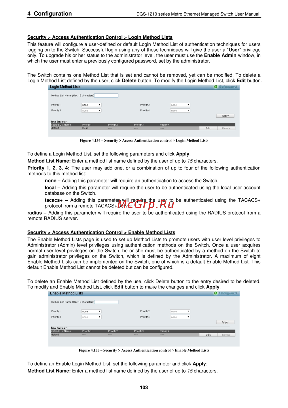
4 Configuration DGS 1210 series Metro Ethernet Managed Switch User Manual Security Access Authentication Control Login Method Lists This feature will configure a user defined or default Login Method List of authentication techniques for users logging on to the Switch Successful login using any of these techniques will give the user a User privilege only To upgrade his or her status to the administrator level the user must use the Enable Admin window in which the user must enter a previously configured password set by the administrator The Switch contains one Method List that is set and cannot be removed yet can be modified To delete a Login Method List defined by the user click Delete button To modify the Login Method List click Edit button Login Method Lists ____ O safeguard Metiod List Nana Max 1 characters Priera 1 ПО1Э Pricrty 3 1 nono P ionty2 1 ncre P iorityl 1 ncrc Apply Tutd Eriliies 1 VICHIuc uici vainc local Edit De Gte 1 Figure 4 154 Security Access Authentication control Login Method Lists To define a Login Method List set the following parameters and click Apply Method List Name Enter a method list name defined by the user of up to 15 characters Priority 1 2 3 4 The user may add one or a combination of up to four of the following authentication methods to this method list none Adding this parameter will require an authentication to access the Switch local Adding this parameter will require the user to be authenticated using the local user account database on the Switch tacacs Adding this parameter will require the user to be authenticated using the TACACS protocol from a remote TACACS server radius Adding this parameter will require the user to be authenticated using the RADIUS protocol from a remote RADIUS server Security Access Authentication Control Enable Method Lists The Enable Method Lists page is used to set up Method Lists to promote users with user level privileges to Administrator Admin level privileges using authentication methods on the Switch Once a user acquires normal user level privileges on the Switch he or she must be authenticated by a method on the Switch to gain administrator privileges on the Switch which is defined by the Administrator A maximum of eight Enable Method Lists can be implemented on the Switch one of which is a default Enable Method List This default Enable Method List cannot be deleted but can be configured To delete an Enable Method List defined by the use click Delete button to the entry desired to be deleted To modify and Enable Method List click Edit button to make the changes and click Apply Figure 4 155 Security Access Authentication control Enable Method Lists To define an Enable Login Method List set the following parameter and click Apply Method List Name Enter a method list name defined by the user of up to 15 characters 103