
Gigabyte GA-8IE800 Инструкция по эксплуатации онлайн
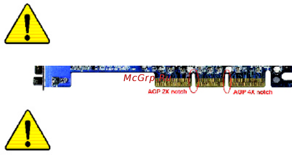
When you installing AGP card, please make sure the follow
ing notice is fully understood and practiced. If your AGP
card has "AGP 4X notch"(show below), please make sure
your AGP card is AGP 4X (1.5V).
Caution: AGP 2X(3.3V) card is not supported by Intel
®
845
(E/G)/ Intel
®
850(E) . You might experience system unable to
boot up normally. Please insert an AGP 4X(1.5V) card
Example 1: Diamond Vipper V770 golden finger is compatible
with 2X/4X mode AGP slot. It can be switched between AGP 2X
(3.3V) or 4X(1.5V) mode by adjusting the jumper. The factory
default for this card is 2X(3.3V). The GA-8IE800 (or any AGP 4X
only) motherboards might not function properly, if you install this card
without switching the jumper to 4X(1.5) mode in it.
Example 2: Some ATi Rage 128 Pro graphics cards made by
"Power Color", the graphics card manufacturer & some SiS 305
cards, their golden finger is compatible with 2X/4X mode AGP
slot, but they support 2X(3.3V) only.The GA-8IE800 (or any AGP
4X only) motherboards might not function properly, If you install this
card in it.
Note : Although Gigabyte's AG32S(G) graphics card is based on
ATi Rage 128 Pro chip, the design of AG32S(G) is compliance
with AGP 4X (1.5V) specification. Therefore, AG32S (G)will work
fine with Intel
®
845(E/G) / 850(E) based motherboards.
Содержание
- Declaration of conformity 3
- Declare that the product 3
- Description of the apparatus sy stem installation to w hich it refers 3
- G b t technology träding gmbh ausschlager weg 41 1f 20537 hamburg germany 3
- In accordance with 89 336 eec emc directive 3
- Mother board ga 8ie800 is in conformity with 3
- Reference to the specification under which conformity is declared 3
- Timmy huang 3
- We manufacturer importer full address 3
- Declaration of conformity 4
- Ga 8ie800 p4 titan motherboard 5
- User s manual 5
- Chapter 1 introduction 6
- Chapter 2 hardware installation process 6
- Chapter 3 bios setup 5 6
- English 6
- Item checklist warning 6
- Table of content 6
- Chapter 4 technical reference 1 7
- Chapter 5 appendix 5 7
- English 7
- English 8
- Installing the motherboard to the chassis 8
- Item checklist 8
- Warning 8
- Chapter 1 introduction 9
- English 9
- Features summary 9
- English 10
- English 11
- Ga 8ie800 11
- Ga 8ie800 motherboard layout 11
- Introduction 7 11
- P4 titan 11
- Chapter 2 hardware installation process 12
- English 12
- Angling the rod to 6 13
- English 13
- If you do not match the cpu socket pin 1 and cpu cut edge well it will cause improper installation please change the insert orientation 13
- Pin1 indicator 13
- Please make sure the cpu type is supported by the motherboard 13
- Socket actuation 13
- Step 1 1 cpu installation 13
- Step 1 install the central processing unit cpu 13
- English 14
- Step 1 2 cpu heat sink installation 14
- English 15
- Step 2 install memory modules 15
- English 16
- Step 3 install expansion cards 16
- English 17
- Ps 2 keyboard and ps 2 mouse connector 17
- Step 4 1 i o back panel introduction 17
- Step 4 connect ribbon cables cabinet wires and power 17
- Supply 17
- Usb connector 17
- Audio connectors 18
- English 18
- Game midi ports 18
- Parallel port vga port and serial ports coma 18
- English 19
- Step 4 2 connectors jumper setting introduction 19
- 16 ga 8ie800 motherboard 20
- Cpu_fan cpu fan connector 20
- English 20
- Please note a proper installation of the cpu cooler is essential to prevent the cpu from running under abnormal condition or damaged by overheating the cpu fan connector supports max current up to 600 ma 20
- Sys_fan system fan connector 20
- This connector allows you to link with the cooling fan on the system case to lower the system temperature 20
- 17 hardware installation process 21
- Ac power cord should only be connected to your power supply unit after atx power cable and other related devices are firmly connected to the mainboard 21
- Atx_12v 12v power connector 21
- Atx_power atx power 21
- English 21
- This connector atx _12v suppliesthe cpu operation voltage vcore if this atx_ 12v connector is not connected system cannot boot 21
- English 22
- Fdd floppy connector 22
- Ide1 ide2 ide1 ide2 connector 22
- 2x_det 23
- English 23
- Pwr_led 23
- 20 ga 8ie800 motherboard 24
- Be careful with the polarity of the front usb connector check the pin assignment while you connect the front usb cable please contact your nearest dealer for optional front usb cable 24
- English 24
- F_ usb1 f_usb2 front usb connector yellow 24
- F_panel 2x10 pins connector 24
- Please connect the power led pc peaker reset switch and power switch etc of your chassis front panel to the f_panel connector according to the pin assignment above 24
- 21 hardware installation process 25
- English 25
- Please contact your nearest dealer for optional sur_cen cable 25
- Spdif_io spdif in out 25
- Sur_cen 25
- The spdif output is capable of providing digital audio to external speakers or compressed ac3 data to an external dolby digital decoder use this feature only when your stereo system has digital input function use spdif in feature only when your device has digital output function 25
- 22 ga 8ie800 motherboard 26
- Aux_in aux in connector 26
- Cd_in cd in blank 26
- Connect cd rom or dvd rom audio out to the connector 26
- Connect other device such as pci tv tunner audio out to the connector 26
- English 26
- 23 hardware installation process 27
- Ci case open 27
- English 27
- F_audio f_audio connector 27
- If you want to use front audio connector you must remove 5 6 9 10 jumper in order to utilize the front audio header your chassis must have front audio connector also please make sure the pin assigment on the cable is the same as the pin assigment on the mb header to find out if the chassis you are buying support front audio connector please contact your dealer 27
- This 2 pin connector allows your system to enable or disable the case open item in bios if the system case begin remove 27
- Battery battery 28
- Caution 28
- Clr_pwd 28
- English 28
- Chapter 3 bios setup 29
- Control keys 29
- English 29
- Entering setup 29
- Advanced bios features 30
- English 30
- Getting help 30
- If you can t find the setting you want please press ctrl f1 to search the advanced option widden 30
- Main menu 30
- Standard cmos features 30
- Status page setup menu option page setup menu 30
- The main menu for example bios ver e4 30
- The on line description of the highlighted setup function is displayed at the bottom of the screen 30
- This setup page includes all the items in standard compatible bios 30
- This setup page includes all the items of award special enhanced features 30
- To accept or enter the sub menu 30
- English 31
- English 32
- Standard cmos features 32
- Drive a drive b 33
- English 33
- Floppy 3 mode support for japan area 33
- Ide primary master slave secondary master slave 33
- The category identifies the types of floppy disk drive a or drive b that has been installed in the computer 33
- Base memory 34
- English 34
- Extended memory 34
- Halt on 34
- Installed in the system 34
- Memory 34
- The bios determines how much extended memory is present during the post 34
- The category determines whether the computer will stop if an error is detected during power up 34
- The category is display only which is determined by post power on self test of the bios 34
- The post of the bios will determine the amount of base or conventional memory 34
- The value of the base memory is typically 512 k for systems with 512 k memory installed on the motherboard or 640 k for systems with 640 k or more memory installed on the motherboard 34
- This is the amount of memory located above 1 mb in the cpu s memory address map 34
- Advanced bios features 35
- English 35
- First second third boot device 35
- This feature allows you to select the boot device priority 35
- Boot up floppy seek 36
- Cpu hyper threading 36
- Dram data integrity mode 36
- English 36
- Init display first 36
- Password check 36
- System the system can not boot and can not access to setup page will be denied 36
- This feature allows you to select the first initation of the monitor display from which card when you install an agp vga card and a pci vga card on board 36
- English 37
- Integrated peripherals 37
- Disable this option if you are not using the onboard usb feature 38
- English 38
- Ide1 conductor cable 38
- Ide2 conductor cable 38
- On chip primary pci ide 38
- On chip secondary pci ide 38
- Usb controller 38
- Used set at disabled 38
- When enabled allows you to use the onboard primary pci ide if a hard disk controller card is used set at disabled 38
- When enabled allows you to use the onboard secondary pci ide if a hard disk controller card is 38
- Ac97 audio 39
- English 39
- Onboard serial port 1 39
- Onboard serial port 2 39
- Usb keyboard support 39
- Usb mouse support 39
- When a usb keyboard is installed please set at enabled 39
- Ecp mode use dma 40
- English 40
- Game port address 40
- Midi port address 40
- Midi port irq 40
- Onboard parallel port 40
- Parallel port mode 40
- This feature allows you to connect with an advanced print via the port mode it supports 40
- This feature allows you to select from a given set of parameters if the parallel port uses the onboard i o controller 40
- English 41
- Power management setup 41
- Acpi suspend type 42
- English 42
- Modem ring on 42
- Pme event wake up 42
- Power led in s1 state 42
- Resume by alarm 42
- Soft off by pwr bttn 42
- When set at enabled any pci pm event awakes the system from a pci pm controlled state 42
- Ac back function 43
- English 43
- Kb power on password 43
- Power on by keyboard 43
- Power on by mouse 43
- The option keyboard 98 allows you to use the standard keyboard 98 to power on the system 43
- The option password allows you to set up to 5 alphanumeric characters to power on the system 43
- This feature allows you to set the method for powering on the system 43
- English 44
- Pci1 pci5 irq assignment 44
- Pci2 irq assignment 44
- Pci3 irq assignment 44
- Pci4 irq assignment 44
- Pnp pci configurations 44
- Current voltage v vcore vcc18 3 v 5v 12v 45
- English 45
- Pc health status 45
- Reset case open status case opened 45
- Cpu fan fail warning 46
- Cpu warning temperature 46
- Current cpu system fan speed rpm 46
- Current cpu temperature 46
- English 46
- System fan fail warning 46
- Cpu clock ratio 47
- Cpu host clock control 47
- Cpu host frequency mhz 47
- English 47
- Fixed pci agp frequency 47
- Frequency voltage control 47
- Those items will be available when cpu host clock control is set to enabled 47
- Agp overvoltage control 48
- Cpu overvoltage control 48
- Dimm overvoltage control 48
- English 48
- Host dram clock ratio 48
- Memory frequency mhz 48
- Pci agp frequency mhz 48
- Disabled 49
- Enabled 49
- English 49
- If you wish to maximize the performance of your system set top performance as enabled 49
- Top performance 49
- English 50
- Fail safe defaults contain the most appropriate values of the system parameters that allow minimum system performance 50
- Load fail safe defaults 50
- Load fail safe defaults y n n 50
- English 51
- Load optimized defaults 51
- Load optimized defaults y n n 51
- Selecting this field loads the factory defaults for bios and chipset features which the system automatically detects 51
- English 52
- Enter password 52
- For the password every time the system is rebooted or any time you try to enter setup menu 52
- If you select setup at security option in advance bios features menu you will be prompted only when you try to enter setup 52
- If you select system at security option in advance bios features menu you will be prompted 52
- Set supervisor user password 52
- The bios setup program allows you to specify two separate passwords a supervisor pass word and a user password when disabled anyone may access all bios setup program function when enabled the supervisor password is required for entering the bios setup program and having full configuration fields the user password is required to access only basic items 52
- To abort the selection and not enter a password 52
- When you are prompted to enter password a message password disabled will appear to confirm the password being disabled once the password is disabled the system will boot and you can enter setup freely 52
- When you select this function the following message will appear at the center of the screen to assist you in creating a password 52
- You will be asked to confirm the 52
- English 53
- Save exit setup 53
- Save to cmos and exit y n y 53
- Type n will return to setup utility 53
- Type y will quit the setup utility and save the user setup value to rtc cmos 53
- English 54
- Exit without saving 54
- Quit without saving y n n 54
- Type n will return to setup utility 54
- Type y will quit the setup utility without saving to rtc cmos 54
- Block diagram 55
- Chapter 4 technical reference 55
- English 55
- Bios introduction 56
- English 56
- Gigabyte announces bios windows bios live update utility 56
- Easy tun 57
- Easytune 4 carries on the heritage so as to pave the way for future generations 57
- English 57
- Gigabyte announces easytun 57
- Introduction 57
- Windows based overclocking utility 57
- Bios flash procedur 58
- English 58
- Program to flash bios 58
- Yte bio 58
- English 59
- English 60
- English 61
- English 62
- 2 once you enter the bios setup utility the main menu will appear on the screen use the arrows to highlight the item bios features setup 63
- English 63
- Key to enter bios setup main menu when system is boot up 63
- Step 4 make sure the system will boot from the floppy disk 63
- 1st boot device and then use the page up or page down keys to select floppy 64
- 3 press enter to enter bios features setup menu use the arrows to highlight the item 64
- 4 press esc to go back to previous screen use the arrows to highlight the item save 64
- English 64
- Exit setup then press enter system will ask save to cmos and exit y n press y and enter keys to confirm now the system will reboot automatically the new bios setting will be taken effect next boot up 64
- Save to cmos and exit y n y 64
- English 65
- English 66
- English 67
- Key to enter bios setup again when system is boot up use the arrows to highlight the item load setup defaults then press enter system will ask load setup defaults y n press y and enter keys to confirm 67
- Load setup defaults y n n 67
- Normally the system redetects all devices after bios has been upgraded therefore we highly recommend reloading the bios defaults after bios has been upgraded this important step resets everything after the flash 1 take out the floppy diskette from floppy drive and then restart the system the boot up screen will indicate your motherboard model and current bios version 67
- Step 6 load bios defaults 67
- 3 use the arrows to highlight the item save exit setup and press enter system will 68
- 4 congratulate you have accomplished the bios flash procedure 68
- Ask save to cmos and exit y n press y and enter keys to confirm now the system will reboot automatically the new bios setting will be taken effect next boot up 68
- English 68
- Save to cmos and exit y n y 68
- A what is q flash utility 69
- B how to use q flash 69
- B q flash utility 69
- English 69
- Enter q flash utility y n y 69
- Flash type size sst 39sf020 256k keep dmi data yes 69
- Load bios from floppy save bios to floppy 69
- Method 2 69
- Mode no more fooling around any os 69
- Q flash introduction 69
- Q flash utility is a pre o s bios flash utility enables users to update its bios within bios 69
- Q flash utility v3 5 69
- Space bar change value enter run esc reset select item 69
- To enter q flash utility 69
- English 70
- Load bios from floppy 70
- Bios flash procedure 71
- English 71
- English 72
- English 73
- Function 73
- Revision history 2 4 6 channel audio function introuction 73
- Stereo speakers connection and settings 73
- The installation of windows 98se 2k me xp is very simple please follow next step to install the 73
- Channel analog audio output mode 74
- English 74
- Basic 6 channel analog audio output mode 75
- English 75
- Advanced 6 channel analog audio output mode using audio combo kit optional device 76
- English 76
- Basic advanced 6 channel analog audio output mod 77
- English 77
- English 78
- Chapter 5 appendix 79
- English 79
- Install chipset driver 79
- Install drivers 79
- Revision history 79
- English 80
- Item description 80
- English 81
- Software application 81
- English 82
- English 83
- English 84
- English 85
- 82 ga 8ie800 motherboard 86
- English 86
- If you encounter any trouble during boot up please follow the troubleshooting procedures 86
- Troubleshooting 86
- Appendix 83 87
- English 87
- If the above procedure unable to solve your problem please contact with your local retailer or national distributor for help or you could submit your question to the service mail via gigabyte website technical support zone http www gigabyte com tw the appropriate response will be provided asap 87
- English 88
- Technical support rma sheet 88
- Acronyms 89
- English 89
- English 90
- English 91
- English 92
- English 93
- English 94
- English 95
- 92 ga 8ie800 motherboard 96
- Contact us 96
- Contact us via the information in this page all over the world 96
- English 96
Похожие устройства
- Bosch WAA18160BY Инструкция по эксплуатации
- Thermos CanTote B Инструкция по эксплуатации
- Ballu BSN-09HN1 Инструкция по эксплуатации
- Gigabyte GA-8IE533 Инструкция по эксплуатации
- Daewoo Electronics DTF-2950R-100D Инструкция по эксплуатации
- Thermos PFlower Инструкция по эксплуатации
- Ballu BSN-12HN1 Инструкция по эксплуатации
- Gigabyte GA-8IG1000 Pro (rev. 2.x) Инструкция по эксплуатации
- Vitek VT-1760 Инструкция по эксплуатации
- Thermos 100335 Black Инструкция по эксплуатации
- Ballu BSN-18HN1 Инструкция по эксплуатации
- Gigabyte GA-8IG1000 Pro (rev. 1.x) Инструкция по эксплуатации
- Samsung RL25DAT* Инструкция по эксплуатации
- Thermos 100314 Black Инструкция по эксплуатации
- Ballu BSN-24HN1 Инструкция по эксплуатации
- Gigabyte GA-8IG1000 (rev. 3.x) Инструкция по эксплуатации
- JVC XV-N55SL Инструкция по эксплуатации
- Motorola S2001 Инструкция по эксплуатации
- Ballu BSТ-07HN1 Инструкция по эксплуатации
- Gigabyte GA-8IG1000 (rev. 2.x) Инструкция по эксплуатации