
Cyberpower BP100-12V Инструкция по работе онлайн
Quick Start Guide
Battery Management System
BM100
BP100-12V
Battery Management System
BM100
BP100-12V
Copyright © 2018 Cyber Power Systems, Inc. All rights reserved.
1
32
INSTALLATION GUIDE
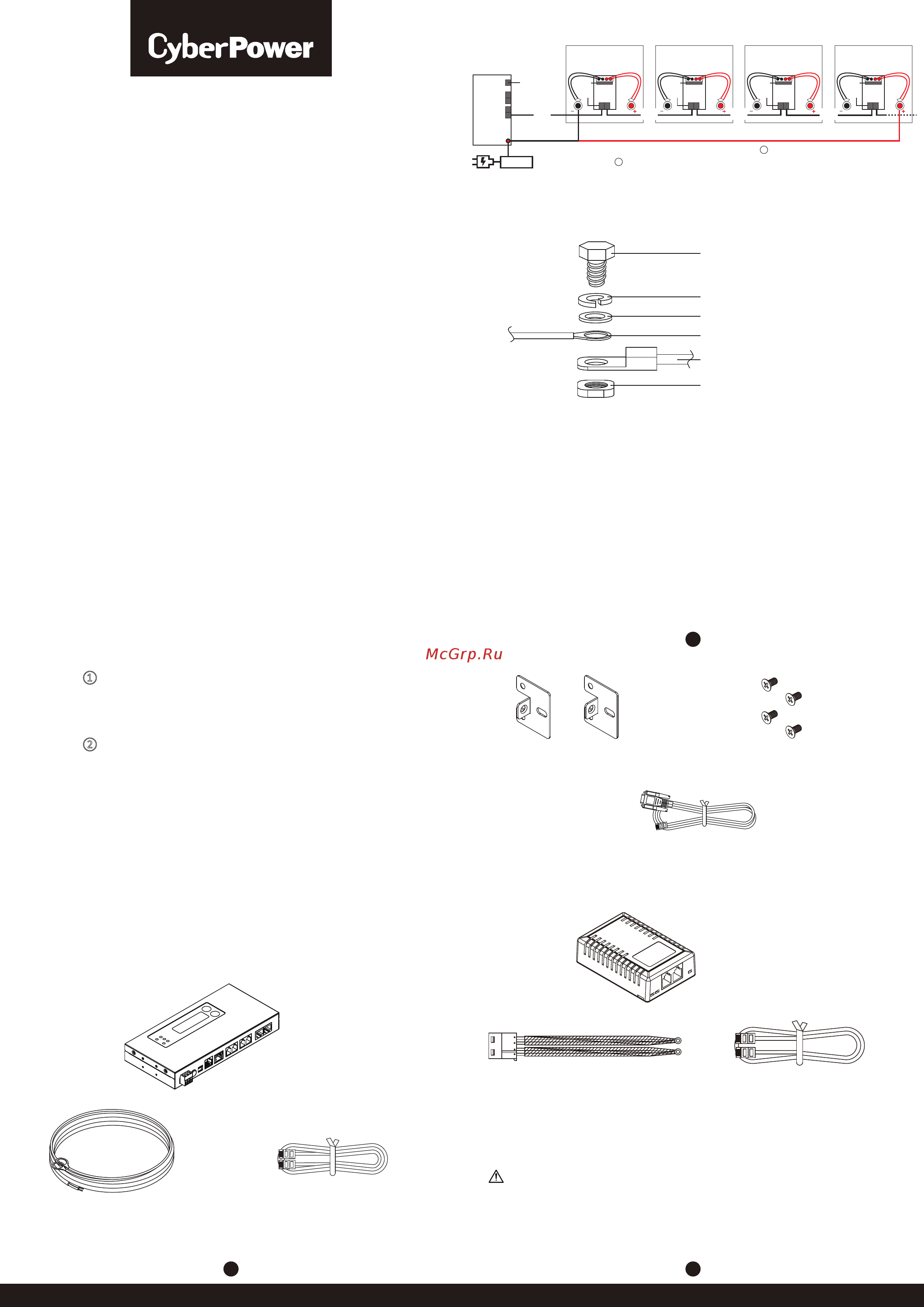
PRODUCT CONTENTS
Power Cable*
(244cm; L4)
Communication Cable (x4)
(90cm; L1)
2 Mounting Brackets
4 Bracket Mounting Screws
DB9/RJ45 Communication Cable (183cm)
Battery Manager
BM100
Battery Manager
Battery Probe
Battery Probe
BP100-12V
Battery Connecting Cable
(30cm; L3)
Probe Communication Cable
(30cm; L2)
1. Connect the battery connecting cable (L3) to each battery. Make sure
that the ring terminals of the battery connecting cable (L3) are installed
above the battery series connection wire.
Note: Please see below illustration for correct installation.
*For 4 or less batteries per string.
WARNING: This product can expose you to chemicals including Styrene,
which is known to the State of California to cause cancer, and Bisphenol-A,
which is known to the State of California to cause birth defects or other
reproductive harm.
For more information go to www.P65Warnings.ca.gov.
2. Connect the cable to each Battery Probe through battery connector (CN3).
3. Fix each Battery Probe to each battery with Loop tape.
Note: When fixing the Battery Probes to the batteries, make sure it is
easy to observe the LED indicators of the Battery Probe.
4. Connect the Battery Manager’s ‘A’ (RJ25) port to the ‘Left’ (‘In’) RJ25
port (CN1) of the first Battery Probe with the communication cable (L1).
5. Connect Battery Probes with one another through RJ25 ports (CN1) of
Battery Probes with probe communication cables (L2), and up to 50
Battery Probes in a string.
6. Connect an Ethernet cable to the Ethernet port of the Manager.
7. Provide power to the Battery Manager through the DC power (CN4). The
required Battery Manager input voltage is 15V min, 60V max.
Pole screw
Spring washer
Washer
Ring terminal of separate wire
Battery connector
Battery pole
Scenario ①
For 4 or less batteries per string: Use the included power cable (L4) to
connect the Battery Manager. (Warning: A battery can present a high
risk of short circuit current and electrical shock. Please pay attention to
the input voltage.)
Scenario ②
For 5 or more batteries per string: Connect the Battery Manager to the
utility power with an AC/DC adapter cord.
8. Press the RESTART button for one second to restart the system.
9. IP address will show on the LCD interface once the Manager is powered
and the system is initialized, or you can find it through [About →
Network info. → IPv4 address]. Use the IP address to login to the Web
Interface. The factory default Username/Password is admin/admin.
NOTE: Once the number of battery string and connected battery has been
changed from last configuration, please configure it via web interface
on the [Battery → Configuration], select the number of string(s) and
batteries per string, and then click Apply. Or you can reset the
system to the factory default setting via LCD interface on the
[Reset/Reboot → Reset → Confirm].
D
C
B
A
CN4
Battery
Manager
L4 (Scenario )
L1
Ethernet
L2
Max. 50 batteries
AC/DC
Adapter (Scenario )
L2
2
1
Battery #1
L3
Probe
CN3
CN1
Battery #2
L3
Probe
CN3
CN1
Battery #3
L3
Probe
CN3
CN1
Battery #4
L3
Probe
CN3
CN1
L2
Red
Black
RedBlack
Содержание
Похожие устройства
- Cyberpower BP100-12V Руководство пользователя
- Cyberpower BP100-12V Техническое описание
- Cyberpower BPE36V60ART2US Руководство пользователя
- Cyberpower BPE36V60ART2US Техническое описание
- Cyberpower BPSE36V45ART2U Руководство пользователя
- Cyberpower BPSE36V45ART2U Техническое описание
- Cyberpower BPE48V75ART2U Руководство пользователя
- Cyberpower BPE48V75ART2U Техническое описание
- Cyberpower BPE72V60ART2US Руководство пользователя
- Cyberpower BPE72V60ART2US Техническое описание
- Energy MIG 160 Инструкция по эксплуатации
- Energy MIG 200 Инструкция по эксплуатации
- Grovers MIG 200P Инструкция по эксплуатации
- Grovers MIG 200C Инструкция по эксплуатации
- Cyberpower BPSE72V45A Руководство пользователя
- Cyberpower BPSE72V45A Техническое описание
- Grovers MULTIMIG 200 SYN Инструкция по эксплуатации
- Grovers MIG 250T Инструкция по эксплуатации
- Grovers MIG250 Инструкция по эксплуатации
- Cyberpower BPSE72V45ART2U Руководство пользователя