
Neff T23R46N0 Инструкция по эксплуатации онлайн
*9000407456* 9000407456 Y
Ø Montageanleitung
Ú Installation instructions
Û Instrucciones de montaje
Þ Notice de montage
â Istruzioni per il montaggio
é Installatievoorschrift
ë Instrukcja montażu
ì Instruções de montagem
î Инструкция по монтажу
ô Montaj kılavuzu
PLQ
PD[
PLQ
PLQ
PLQ
PLQ
PD[
Содержание
- A austausch der düsen abb 7 7a 4
- Ausbau des kochfeldes 4
- Drehen sie die klammern und ziehen sie diese fest an 4
- Einbau des geräts 4
- Elektrischer anschluss abb 6 4
- Fügen sie das kochfeld mittig ein 4
- Gasanschluss abb 5 4
- Gasaustrittsgefahr 4
- Nehmen sie die roste brennerdeckel und verteiler ab 4
- Schrauben sie die klammern in der angegebenen position an so dass sie sich frei drehen 4
- Sicherheitshinweise 4
- Tauschen sie die düsen mit dem über unseren kundendienst erhältlichen schlüssel mit der artikelnummer 340847 aus für doppelbrenner und dreiflammenbrenner artikelnummer 340808 siehe tabelle ii achten sie dabei besonders darauf dass die d 4
- Umstellung auf eine andere gasart 4
- Vor dem einbau 4
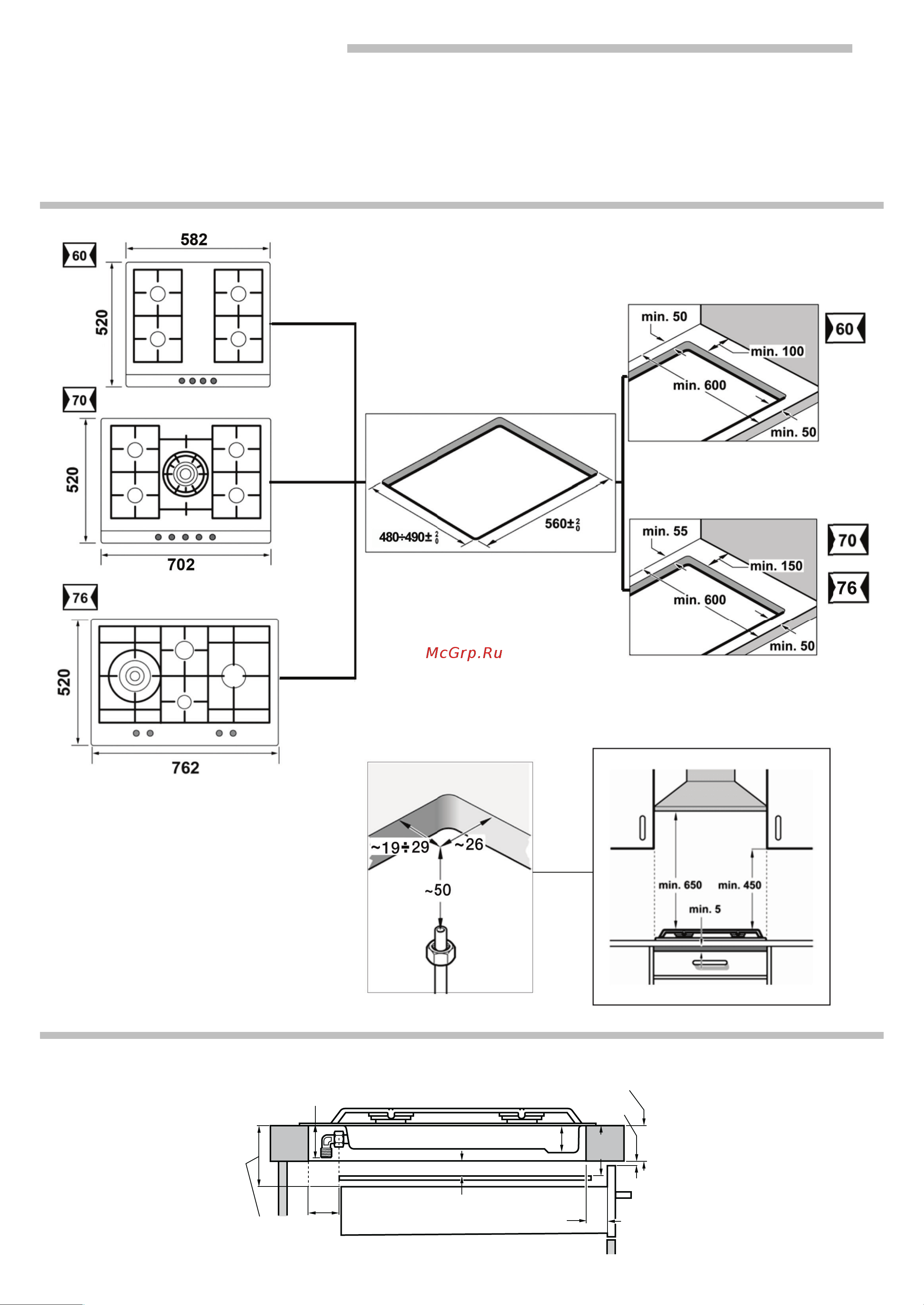
- Vorbereitung des küchenmöbels abb 1 2 4
- B einstellung der gashähne abb 8 5
- Before installing 5
- Bringen sie die verteiler und brennerdeckel auf den entsprechenden kochstellen an und setzen sie die roste korrekt in den entsprechenden halteelementen ein 5
- Danger of leaks 5
- Drehen sie die bedienknebel auf die niedrigste stufe 5
- Electric connection fig 6 5
- Für den wiedereinbau des geräts folgen sie den ausbauanweisungen in umgekehrter reihenfolge 5
- Gas connection fig 5 5
- Insert and centre the hob 5
- Installation of appliance 5
- Lockern sie die brenner schrauben 5
- Nehmen sie alle roste brennerdeckel verteiler und bedienknebel ab 5
- Preparation of the kitchen unit fig 1 2 5
- Removal of hob 5
- Safety precautions 5
- Screw each one of the clips into the position indicated so that they are free to rotate 5
- Stellen sie die minimale gaszufuhr ein indem sie die bypass schraube mit einem schlitzschraubenzieher drehen 5
- Turn the clips and tighten them fully 5
- Verwenden sie ggf den bei unserem kundendienst erhältlichen demontagehebel 483196 lösen sie die vordere clip befestigung indem sie den hebel in den markierten bereichen ansetzen abb 9 5
- Ziehen sie die bedienknebel der gashähne ab es wird eine knebeldichtung aus flexiblem gummi sichtbar drücken sie diese mit der schraubendreherspitze beiseite um an die einstellschraube des gashahns zu gelangen 5
- A changing the nozzles fig 7 7a 6
- Adjust the minimum ring setting by turning the by pass screw using a flat head screwdriver 6
- Antes de la instalación 6
- Atornille cada una de las grapas en la posición indicada dejando que giren libremente 6
- B adjusting the taps fig 8 6
- Change the nozzles using the spanner code 340847 code 340808 for double flame burners or triple flame burners provided by our technical assistance service see table ii taking special care to ensure that the nozzle does not fall when it is remo 6
- Changing the gas type 6
- Conexión de gas fig 5 6
- Desmontaje de la placa de cocción 6
- Encastre y centre la placa de cocción 6
- Gire las grapas y apriételas a fondo 6
- If necessary use the disassembly lever 483196 availablle from our technical assistance service to release the front clips apply the lever to the area shown in figure 9 6
- Indicaciones de seguridad 6
- Instalación del aparato 6
- Position the diffusers and burner caps on the corresponding rings and the pan supports on their fasteners 6
- Preparación del mueble fig 1 2 6
- Remove all pan supports burner caps diffusers and control knobs 6
- Remove the control knobs from the taps it has a flexible rubber valve reinforcing ring press with the tip of the screwdriver to access the tap s adjusting screw 6
- Remove the pan supports burner caps and diffusers 6
- Remove the screws from the burners 6
- Set the control knobs to minimum 6
- To reinstall the appliance proceed in the reverse order to disassembly 6
- A cambio de inyectores fig 7 7a 7
- Avant l installation 7
- B reglaje de los grifos fig 8 7
- Cambie los inyectores usando la llave disponible a través de nuestro servicio técnico con código 340847 para quemadores de doble o triple llama código 340808 ver tabla ii teniendo especial cuidado en que no se desprenda el inyector al reti 7
- Cambio del tipo de gas 7
- Coloque los difusores y las tapas de los quemadores en sus correspondientes fuegos y las parrillas en sus elementos de sujeción 7
- Coloque los mandos en la posición de mínimo 7
- Conexión eléctrica fig 6 7
- Indications de sécurité 7
- Para volver a montar el aparato proceda de modo inverso al desmontaje 7
- Peligro de fuga 7
- Préparation du meuble fig 2 7
- Quite todas las parrillas tapas de los quemadores difusores y mandos 7
- Regule el fuego mínimo girando el tornillo bypass mediante un destornillador de punta plana 7
- Retire las parrillas tapas de quemador y difusores 7
- Retire los mandos de los grifos se encontrará con un retén de goma flexible presione con la punta del destornillador para acceder al tornillo de regulación del grifo 7
- Si es necesario utilice la palanca de desmontaje 483196 disponible a través de nuestro servicio técnico libere el clipaje delantero aplicando la palanca en las zonas señaladas fig 9 7
- Suelte los tornillos de los quemadores 7
- A changement des injecteurs fig 7 7a 8
- B réglage des robinets fig 8 8
- Branchement de gaz fig 5 8
- Branchement électrique fig 6 8
- Changement du type de gaz 8
- Changez les injecteurs en utilisant la clé disponible réf 340847 auprès de notre service technique pour brûleurs double ou triple flamme réf 340808 cf tableau ii en faisant particulièrement attention à ne pas déloger l injecteur 8
- Desserrez les vis des brûleurs 8
- Démontage de la plaque de cuisson 8
- Encastrez et centrez la plaque de cuisson 8
- Indicazioni di sicurezza 8
- Installation de l appareil 8
- Placez les boutons de commande sur la position minimum 8
- Placez les diffuseurs et les couvercles des brûleurs sur les feux correspondants et les grilles sur leurs éléments de fixation 8
- Pour remonter l appareil suivez la procédure inverse au démontage 8
- Retirez les commandes des robinets vous trouverez alors une bague en caoutchouc flexible appuyez avec la pointe du tournevis afin d accéder à la vis de réglage du robinet 8
- Retirez les grilles les couvercles de brûleur et les diffuseurs 8
- Risque de fuites 8
- Réglez le feu minimum en tournant la vis by pass à l aide d un tournevis à pointe plate 8
- Si nécessaire utilisez le levier de démontage 483196 disponible chez notre service technique libérez l ensemble de clips avant en appliquant le levier sur les zones indiquées fig 9 8
- Tournez les agrafes et serrez les à fond 8
- Vissez chacune des agrafes dans la position indiquée en les laissant tourner librement 8
- Ôtez tous les grilles couvercles des brûleurs diffuseurs et boutons de commande 8
- A sostituzione degli iniettori fig 7 7a 9
- Attacco del gas fig 5 9
- Avvitare ognuna delle graffe nella posizione indicata lasciandole girare liberamente 9
- B regolazione dei rubinetti fig 8 9
- Cambio del tipo di gas 9
- Collocare i diffusori e i coperchi dei bruciatori sui fuochi corrispondenti e le griglie sugli appositi elementi di sostegno 9
- Collocare le manopole nella posizione di minimo 9
- Connessione elettrica fig 6 9
- Estrarre le manopole dei rubinetti si troverà una tenuta in gomma flessibile esercitare pressione con la punta del cacciavite per accedere alla vite di regolazione del rubinetto 9
- Girare le graffe e stringerle a fondo 9
- Incassare e centrare il piano di cottura 9
- Installazione dell apparecchio 9
- Per rimontare l apparecchio invertire la procedura di smontaggio 9
- Pericolo di fughe 9
- Preparazione del mobile fig 1 2 9
- Prima dell installazione 9
- Regolare il fuoco minimo girando la vite di by pass con un cacciavite a punta piatta 9
- Rimuovere le griglie i coperchi del bruciatore e i diffusori 9
- Rimuovere le viti dei bruciatori 9
- Se necessario utilizzare la leva di smontaggio 483196 disponibile presso il nostro servizio tecnico rilasciare il fissaggio a clip anteriore facendo leva nelle zone indicate fig 9 9
- Smontaggio del piano di cottura 9
- Sostituire gli iniettori usando la chiave disponibile presso il nostro servizio tecnico codice 340847 340808 per i bruciatori a doppia o tripla fiamma far riferimento alla tabella ii facendo particolare attenzione che l iniettore non si dista 9
- Togliere tutte le griglie i coperchi dei bruciatori i diffusori e le manopole 9
- Veiligheidsaanwijzingen 9
- A vervangen van de inspuiters afb 7 7a 10
- B afstelling van de kranen afb 8 10
- Bouw de kookplaat in en centreer deze 10
- Draai de klemmen helemaal aan 10
- Draai elk van de klemmen in de aangeduide stand en zorg dat deze vrij draaien 10
- Elektrische aansluiting afb 6 10
- Gasaansluiting afb 5 10
- Haal de bedieningsknoppen van de kranen af u treft een flexibele rubberen keerring aan voer met de punt van de schroevendraaier druk uit om bij de stelschroef van de kraan te komen 10
- Installatie van het apparaat 10
- Lekgevaar 10
- Plaats de diffusors en de deksels van de branders op de bijbehorende pitten en de roosters op de bevestigingselementen 10
- Stel de minimumstand af door de bypass bout te draaien met een schroevendraaier met een vlakke punt 10
- Uitbouw van de kookplaat 10
- Verandering van gastype 10
- Vervang de inspuiters met de sleutel die beschikbaar is via onze technische dienst met code 340847 voor branders met dubbele of driedubbele vlam code 340808 zie tabel ii zorg dat de inspuiter niet losraakt bij het verwijderen of bevestigen hi 10
- Verwijder de roosters hoedjes en verspreiders 10
- Voorbereiding van het meubel afb 1 2 10
- Vóór de installatie 10
- Zet de knoppen in de laagste stand 10
- Demontaż płyty kuchenki 11
- Ga om het apparaat terug in te bouwen op omgekeerde wijze te werk dan bij de demontage 11
- Gebruik indien vereist de uitbouwhendel 483196 beschikbaar bij onze technische dienst maak de voorste clips los door deze in de aangeduide zones omhoog te wippen afb 9 11
- Instalacja urządzenia 11
- Maak de bouten van de branders los 11
- Niebezpieczeństwo ulatniania się gazu 11
- Obrócić uchwyty i docisnąć je do końca 11
- Podłączanie gazu rys 5 11
- Podłączanie prądu rys 6 11
- Przed zainstalowaniem 11
- Przygotowanie mebla rys 1 2 11
- Przykręcić każdy z uchwytów we wskazanej pozycji tak by obracały się swobodnie 11
- Verwijder alle roosters hoedjes verspreiders en knoppen 11
- Wskazówki dotyczące bezpieczeństwa 11
- Wsunąć płytę kuchenki i ustawić centralnie w wycięciu mebla 11
- A wymiana dyszy rys 7 7a 12
- Antes da instalação 12
- Aparafuse cada um dos grampos na posição indicada deixando que estes rodem livremente 12
- B regulacja kurków gazu rys 8 12
- Encastre e centre a placa de cozedura 12
- Gire os grampos e aperte os bem 12
- Indicações de segurança 12
- Instalação do aparelho 12
- Należy skorzystać z dźwigni demontującej kod produktu 483196 dostępnej w naszym serwisie technicznym zwolnić przednie zaciski używając dźwigni w zaznaczonych miejscach rys 9 12
- Preparação do móvel fig 1 2 12
- Ustawić wszystkie pokrętła w położeniu minimalnym 12
- W celu ponownego zamontowania formy na tłuszcz należy wykonać czynności demontażu w odwrotnej kolejności 12
- Wyjąć pokrętła z kurków pod spodem znajduje się element zabezpieczający z elastycznej gumy nacisnąć element końcem śrubokrętu aby dostać się do śruby regulacyjnej kurka 12
- Wykręcić śruby z palników 12
- Wymienić dysze za pomocą klucza dostępnego w naszym serwisie technicznym kod produktu 340847 natomiast w przypadku palników o podwójnym lub potrójnym wieńcu płomieni kod produktu 340808 patrz tabela ii zwracając szczególną uwagę 12
- Wyregulować płomień minimalny obracając śrubę złączki przejściowej za pomocą śrubokrętu z płaską końcówką 12
- Założyć dyfuzory i nakładki palników na odpowiednich palnikach i rusztach na właściwych elementach mocujących 12
- Zdjąć ruszty nakładki palnika i dyfuzory 12
- Zdjąć wszystkie ruszty nakładki z palników dyfuzory oraz wyjąć pokrętła 12
- Zmiana rodzaju gazu 12
- A substituição dos injectores fig 7 7a 13
- B regulação das torneiras fig 8 13
- Coloque os comandos na sua posição mínima 13
- Coloque os difusores e as tampas dos queimadores nos respectivos lugares e as grelhas nos respectivos elementos de fixação 13
- Desaperte os parafusos dos queimadores 13
- Desmontagem da placa de cozedura 13
- Ligação a gás fig 5 13
- Ligação eléctrica fig 6 13
- Mudança do tipo de gás 13
- Para voltar a montar o aparelho proceda de modo inverso ao da desmontagem 13
- Perigo de fuga 13
- Regule a chama mínima rodando o parafuso bypass através de uma chave de fendas de ponta plana 13
- Remova todas as grelhas tampas dos queimadores difusores e comandos 13
- Retire as grelhas as tampas de queimador e os difusores 13
- Retire os comandos das torneiras ficará visível um retentor de borracha flexível pressione com a ponta de uma chave de fendas para aceder ao parafuso de regulação da torneira 13
- Se necessário utilize a alavanca de desmontagem 483196 disponível através do nosso serviço de assistência técnica retire o clipe dianteiro colocando a alavanca nas zonas assinaladas fig 9 13
- Substitua os injectores usando a chave disponibilizada pelo nosso serviço de assistência técnica com o código 340847 para queimadores de chama dupla ou tripla código 340808 ver tabela ii tendo especial atenção para que o injector nã 13
- Перед началом установки 13
- Правила техники безопасности 13
- A замена жиклеров рис 7 7a 14
- Cihazı kurmadan veya kullanmadan önce talimatları okuyunuz bu talimatlarda yer alan resimler bilgilendirme amaçlıdır bu kılavuzdaki kurallara uyulmadığı takdirde üretici herhangi bir sorumluluktan muaf olacaktır bu cihaz yalnızca yeterince havalandırılan yerlerde kullanılmalıdır herhangi bir yanma ürünleri tahliye cihazına bağlanmamalıdır bütün kurulum bağlantı ayarlama ve gaz tipine göre uyarlama işlemleri yetkili bir teknisyen tarafından ülkedeki standartlara ve yürürlükteki kanuni yönergeler ile yerel gaz ve elektrik tedarikçisi şirketin talimatlarına uygun olarak 14
- Güvenlik önerileri 14
- Адаптация к другому виду газа 14
- В регулировка кранов рис 8 14
- Вставьте варочную панель в подготовленное отверстие и выровняйте ее 14
- Демонтаж варочной панели 14
- Замените жиклеры с помощью ключа имеющегося в продаже в нашем сервисном центре артикул 340847 конфорка двойного или тройного пламени а 14
- Монтаж прибора 14
- Ослабьте винты крепления горелок 14
- Отрегулируйте минимальную величину пламени повернув байпасный винт с помощью плоской отвертки 14
- Подготовка тумбы рис 1 2 14
- Подключение газа рис 5 14
- Подключение к электросети рис 6 14
- При необходимости используйте рычаг для демонтажа 483196 который можно приобрести в нашем сервисном центре нажатием рычага в указанны 14
- Привинтите все зажимы в нужном положении так чтобы они могли свободно вращаться 14
- Разверните зажимы и туго затяните их 14
- Снимите все решетки крышки горелок рассекатели и ручки управления 14
- Снимите решетки крышки горелок и рассекатели 14
- Снимите ручки кранов под ними находится уплотнительная прокладка из эластичной резины надавите на прокладку кончиком отвертки чтоб 14
- Существует опасность утечки газа 14
- Установите рассекатели и крышки горелок на соответствующие конфорки а решетки на соответствующие опорные элементы 14
- Установите ручки управления в положение минимального пламени 14
- Чтобы установить рабочую панель на место повторите эти действия в обратном порядке 14
- A brülör ucunun değiştirilmesi şek 7 7a 15
- Alev dağıtıcıları ve brülör kapaklarını ilgili kısımlarına ve ızgaraları tespit elemanlarına takınız 15
- B vanaların ayarlanması şek 8 15
- Brülörlerin vidalarını çıkarınız 15
- Cihazın kurulumu 15
- Düz uçlu tornavida ile by pass vidasını çevirerek en düşük alevi ayarlayınız 15
- Elektrikli bağlantı şekil 6 15
- Gaz tipinin değiştirilmesi 15
- Gazlı bağlantı şekil 5 15
- Gerekliyse teknik servisimizden 483196 kodu ile tedarik edebileceğiniz bir demontaj aleti kullanınız aleti belirtilen alanlarda uygulayarak ön kısımdaki bağlantıyı açınız şek 9 15
- Izgaraları brülör kapaklarını ve alev dağıtıcıları çıkarınız 15
- Kumanda düğmelerini minimum konumuna getiriniz 15
- Kurulumdan önce 15
- Kıskaçları döndürünüz ve sıkıca vidalayınız 15
- Kıskaçları rahatça dönebilmelerini sağlayarak belirtilen pozisyonda vidalayınız 15
- Mobilyanın hazırlanması şekil 1 2 15
- Pişirme tezgahının sökülmesi 15
- Sızıntı tehlikesi 15
- Teknik servisimizden 340847 kod numarası ile temin edilebilecek olan anahtarı kullanarak brülör uçlarını değiştiriniz çift alevli brülörler için kod numarası 340808 bkz tablo ii brülöre takarken veya çıkarırken brülör ucun 15
- Tüm brülör kapaklarını ızgaraları ve kumanda düğmelerini sökünüz 15
- Vanaların kumanda düğmelerini çıkartınız esnek bir kauçuk conta ile birlikte bulunur vana ayar vidasına ulaşmak için tornavidanın ucuyla bastırınız 15
- Yağ sıçratma aparatını tekrar takmak için sökme işlemlerinin tersi bir sırayla devam ediniz 15
- Yerleştiriniz ve pişirme tezgahını ortalayınız 15
Похожие устройства
- Akai AWM 458SD Инструкция по эксплуатации
- Vitek VT-1609 Инструкция по эксплуатации
- Quattroclima NORD POLO QV/QN–F9WA Инструкция по эксплуатации
- Neff T12D20X1 Инструкция по эксплуатации
- Vitek VT-1591 Black Инструкция по эксплуатации
- BBK LD1006SI Инструкция по эксплуатации
- Quattroclima NORD POLO QV/QN–F12WA Инструкция по эксплуатации
- Neff N14D30N0 Инструкция по эксплуатации
- Vitek VT-2400 PK Инструкция по эксплуатации
- Vitek VT-3552 Инструкция по эксплуатации
- Quattroclima NORD POLO QV/QN–F18WA Инструкция по эксплуатации
- Neff N34K30N0 Инструкция по эксплуатации
- Vitek VT 1321 серебристо-фиолетовый Инструкция по эксплуатации
- Liebherr BNes..6 Инструкция по эксплуатации
- Quattroclima NORD POLO QV/QN–F24WA Инструкция по эксплуатации
- Vitek VT 2231 Инструкция по эксплуатации
- Daewoo Electronics SD-3100D Инструкция по эксплуатации
- Quattroclima FRESCO QV/QN–F7WA Инструкция по эксплуатации
- Neff T43E20N1 Инструкция по эксплуатации
- Vitek VT-1780 Инструкция по эксплуатации
Скачать
Случайные обсуждения