
Xigmatek Zeus Spectrum Edition Инструкция по эксплуатации онлайн
Содержание
- 7 тт7й w 7 нт7й кйл кей ш 1
- Actual w 594mm x h 420mm a2 folded w 198mm x h 140mm 1
- Add on card installation 1
- All trademarks are the property of their respective owners 1
- Blenden entfernen 1
- Drive screw 1
- Dépose des panneaux 1
- E mail sales xigmatek com 1
- Extraer los paneles 1
- Httlv f t то 1
- I o 7 7k v f a 1
- Instalación de la placa base 1
- Instalado da placa principal 1
- Installation de la carte mère 1
- Motherboard installation 1
- Motherboard installieren 1
- Motherboard screw tempered glass sidepanel 1
- Pci pci e hwtoims7x7 i hl йи 1
- Power supply screw 1
- Removal of panels 1
- Removal of panels rgb led frontpanel optional 1
- Remoçâo dos painéis 1
- Rgb led frontpanel optional 1
- Rubber washer 1
- Sidepanel anti thief screw cable tie 1
- Tempered glass sidepanel screw 1
- Ulobwil 1
- V f í hwjw v f a el7x77 н т 1
- Xigmatek co ltd all rights reserved 1
- Мййжвж я 1
- Нт7й нт7й т й итт 1
- Снятие панелей 1
- Становка материнской платы 1
- Тшйжщ 1
- Я smww яешетш 1
- Front panel fan installation 2
- Liquid cooling installation 2
- Power supply installation 3 hdd 2 ssd installation 2
- Q front 360mm ф top 360mm g rear 120mm 2
- Rear panel fan installation 2
- Тор front fan insatallation 2
- N m 10 0 p ed h 3
- Zues user manual 3
Похожие устройства
- Xigmatek Zeus Инструкция по эксплуатации
- Xigmatek Aquarius Plus Инструкция по эксплуатации
- Xigmatek Triple X Инструкция по эксплуатации
- Xigmatek Sirocon III Инструкция по эксплуатации
- Xigmatek Helios Инструкция по эксплуатации
- Vixter BT-1005 Инструкция по эксплуатации
- Vixter BT-1007 Инструкция по эксплуатации
- Vixter BT-1100 Инструкция по эксплуатации
- Vixter BT-1009 Инструкция по эксплуатации
- Vixter PB-4000 Инструкция по эксплуатации
- Vixter VCW-2800 Инструкция по эксплуатации
- Vixter DT-4010 Инструкция по эксплуатации
- Vixter AO-915P Инструкция по эксплуатации
- SAFUN BCL-18-302 Инструкция по эксплуатации
- SAFUN AG-150-1700VL Инструкция по эксплуатации
- SAFUN AG-180-1700VL Инструкция по эксплуатации
- SAFUN CCS-36-401 Инструкция по эксплуатации
- SAFUN CD-18 Инструкция по эксплуатации
- SAFUN CD-12 Инструкция по эксплуатации
- SAFUN CD-14 Инструкция по эксплуатации
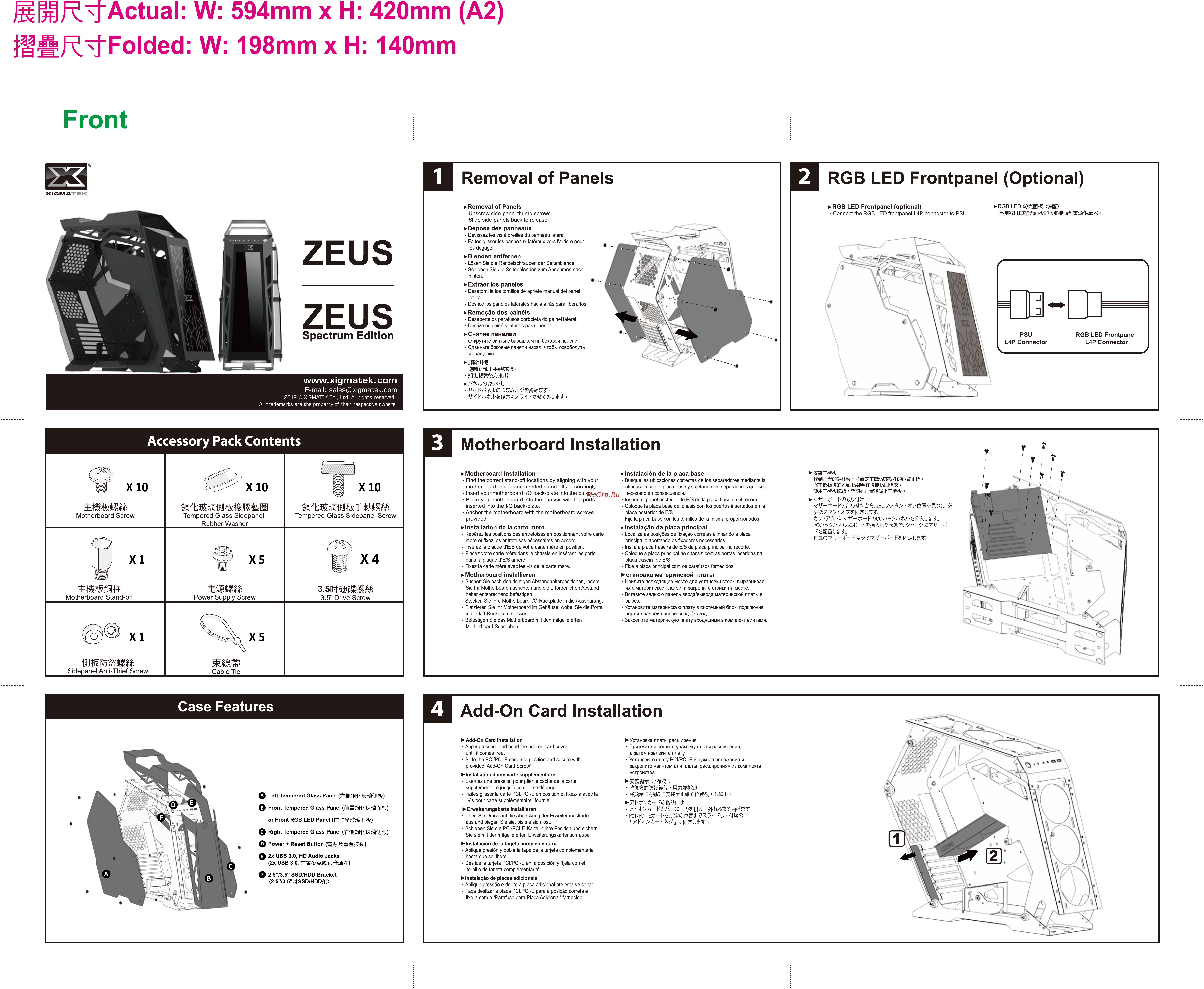
Actual W 594mm x H 420mm A2 Folded W 198mm x H 140mm Front Removal of Panels RGB LED Frontpanel Optional Removal of Panels RGB LED Frontpanel optional XIGMA EK Unscrew side panel thumb screws Slide side panels back to release Connect the RGB LED frontpanel L4P connector to PSU Dépose des panneaux ZEUS Dévissez les vis à oreilles du panneau latéral Faites glisser les panneaux latéraux vers l arrière pour les dégager Blenden entfernen Lösen Sie die Rändelschrauben der Seitenblende Schieben Sie die Seitenblenden zum Abnehmen nach hinten Extraer los paneles ZEUS Spectrum Edition www xigmatek com E mail sales xigmatek com Desatornille los tornillos de apriete manual del panel lateral Deslice los paneles laterales hacia atrâs para liberarlos Remoçâo dos painéis Desaperte os parafusos borboleta do painel lateral Deslize os painéis laterais para libertär Снятие панелей Открутите винты с барашком на боковой панели Сдвиньте боковые панели назад чтобы освободить из защелки Я smww яешетш ULOBWIL 2019 XIGMATEK Co Ltd All rights reserved All trademarks are the property of their respective owners Accessory Pack Contents Motherboard Installation Motherboard Installation X10 Motherboard Screw Tempered Glass Sidepanel Rubber Washer Tempered Glass Sidepanel Screw Power Supply Screw 3 5 Drive Screw Find the correct stand off locations by aligning with your motherboard and fasten needed stand offs accordingly Insert your motherboard I O back plate into the cut out Place your motherboard into the chassis with the ports inserted into the I O back plate Anchor the motherboard with the motherboard screws provided Instalación de la placa base Busque las ubicaciones correctas de los separadores mediante la alineación con la placa base y sujetando los separadores que sea necesario en consecuencia Inserte el panel posterior de E S de la placa base en el recorte Coloque la placa base del chasis con los puertos insertados en la placa posterior de E S Fije la placa base con los tornillos de la misma proporcionados I O Installation de la carte mère Instalado da placa principal Repérez les positions des entretoises en positionnant votre carte mère et fixez les entretoises nécessaires en accord Insérez la plaque d E S de votre carte mère en position Placez votre carte mère dans le châssis en insérant les ports dans la plaque d E S arrière Fixez la carte mère avec les vis de la carte mère Localize as posiqóes de fixagáo corretas alinhando a placa principal e apertando os fixadores necessários Insira a placa traseira de E S da placa principal no recorte Coloque a placa principal no chassis com as portas inseridas na placa traseira de E S Fixe a placa principal com os parafusos fornecidos Motherboard installieren становка материнской платы Suchen Sie nach den richtigen Abstandhalterpositionen indem Sie Ihr Motherboard ausrichten und die erforderlichen Abstand halter entsprechend befestigen Stecken Sie Ihre Motherboard I O Rückplatte in die Aussparung Platzieren Sie Ihr Motherboard im Gehäuse wobei Sie die Ports in die I O Rückplatte stecken Befestigen Sie das Motherboard mit den mitgelieferten Motherboard Schrauben Найдите подходящее место для установки стоек выравнивая их с материнской платой и закрепите стойки на месте Вставьте заднюю панель ввода вывода материнской платы в вырез Установите материнскую плату в системный блок подключив порты к задней панели ввода вывода Закрепите материнскую плату входящими в комплект винтами XI Sidepanel Anti Thief Screw Cable Tie Case Features 4 Add On Card Installation Add On Card Installation Apply pressure and bend the add on card cover until it comes free Slide the PCI PCI E card into position and secure with provided Add On Card Screw Q Left Tempered Glass Panel 0 Front Tempered Glass Panel or Front RGB LED Panel HuUycJgISE 0 Right Tempered Glass Panel OHftI I lliai 0 Power Reset Button JgSSSfiiB 0 2x USB 3 0 HD Audio Jacks 2x USB 3 0 Q 2 5 73 5 SSD HDD Bracket 2 5 73 5 IKtSSD HDD3g Installation d une carte supplémentaire Exercez une pression pour plier le cache de la carte supplémentaire jusqu à ce qu il se dégage Faites glisser la carte PCI PCI E en position et fixez la avec la Vis pour carte supplémentaire fournie Erweiterungskarte installieren Üben Sie Druck auf die Abdeckung der Erweiterungskarte aus und biegen Sie sie bis sie sich lost Schieben Sie die PCI PCI E Karte in ihre Position und sichern Sie sie mit der mitgelieferten Erweiterungskartenschraube Instalación de la tarjeta complementaria Aplique presión y doble la tapa de la tarjeta complementaria hasta que se libere Deslice la tarjeta PCI PCI E en la posición y fíjela con el tornillo de tarjeta complementaria Instalaçâo de placas adicionáis Aplique pressâo e dobre a placa adicional até esta se soltar Faça deslizar a placa PCI PCI E para a posiçâo correta e fixe a com o Parafuso para Placa Adicional fornecido Установка платы расширения Прижмите и согните упаковку платы расширения а затем извлеките плату Установите плату PCI PCI E в нужное положение и закрепите винтом для платы расширения из комплекта устройства МЙЙЖвЖ я 7 ТТ7Й W 7 НТ7Й КйЛ кЕй Ш PCI PCI E HWtOiMS7X7 i HL йИ г7НТ7й НТ7й Т й иТТ ssa s тшйжщ v f í HWJW V f A EL7X77 Н Т 7 7k V f ASB HTTLV f T То RGB LED igBD iSfSRGB