
Yaskawa CIMR-UU4A0040A Инструкция по эксплуатации онлайн
U1000 Industrial MATRIX Drive
Low Harmonic Regenerative Drive for Industrial Applications
Technical Manual
MANUAL NO. SIEP C710636 04C
To properly use the product, read this manual thoroughly and retain
for easy reference, inspection, and maintenance. Ensure the end user
receives this manual.
Type: CIMR-UU
Models:
200 V Class: 7.5 to 75 kW (10 to 100 HP ND)
400 V Class: 5.5 to 260 kW (7.5 to 350 HP ND)
Receiving
Mechanical Installation
Electrical Installation
Start-Up Programming &
Operation
Parameter Details
Troubleshooting
Periodic Inspection &
Maintenance
Peripheral Devices &
Options
Specifications
Parameter List
MEMOBUS/Modbus
Communications
Standards Compliance
Quick Reference Sheet
1
2
3
4
5
6
7
8
A
B
C
D
E
1
2
3
4
5
6
7
8
A
B
C
D
E
Содержание
- Front cover 1
- Low harmonic regenerative drive for industrial applications 1
- Technical manual 1
- U1000 industrial matrix drive 1
- Quick reference 3
- This page intentionally blank 4
- Drive models and enclosure types 37 1 component names 38 5
- I general safety 20 5
- I preface 18 5
- I preface general safety 17 5
- Mechanical installation 47 5
- Model number and nameplate check 34 5
- Quick reference 3 5
- Receiving 29 5
- Section safety 30 1 general description 31 5
- Section safety 48 2 mechanical installation 50 5
- Table of contents 5
- Connect to a pc 8 3 2 emc filter 9 6
- Control circuit wiring 8 6
- Control i o connections 4 6
- Digital operator and front cover 6 6
- Electrical installation 3 6
- External interlock 03 6
- Main circuit wiring 0 6
- Section safety 08 4 using the digital operator 09 6
- Section safety 4 3 standard connection diagram 6 3 main circuit connection diagram 9 3 terminal block configuration 0 3 terminal cover 3 6
- Start up programming operation 107 6
- Top protective cover 9 6
- Wiring checklist 04 6
- A initialization 52 7
- Application selection 27 7
- Auto tuning 30 7
- B application 58 7
- No load operation test run 44 7
- Parameter details 51 7
- Powering up the drive 26 7
- Start up flowcharts 19 7
- Test run checklist 49 7
- Test run with load connected 46 7
- The drive and programming modes 13 7
- Verifying parameter settings and backing up changes 47 7
- C tuning 91 8
- D reference settings 05 8
- E motor parameters 20 8
- F option settings 33 8
- H terminal functions 46 8
- L protection functions 78 8
- Alarm detection 51 9
- Drive alarms faults and errors 30 9
- Fault detection 35 9
- N special adjustments 03 9
- O operator related settings 12 9
- Section safety 22 6 motor performance fine tuning 24 9
- Troubleshooting 21 9
- U monitor parameters 19 9
- Auto tuning fault detection 64 10
- Copy function related displays 69 10
- Diagnosing and resetting faults 71 10
- Drive cooling fans 91 10
- Drive replacement 05 10
- Operator programming errors 60 10
- Periodic inspection maintenance 383 10
- Periodic maintenance 89 10
- Section safety 84 7 inspection 86 10
- Troubleshooting without fault display 74 10
- A drive specifications 35 a drive watt loss data 37 a drive derating data 38 11
- A heavy duty and normal duty ratings 30 a power ratings 31 11
- A specifications 29 11
- B b application 46 11
- B parameter groups 43 b a initialization parameters 44 11
- B parameter list 41 11
- B understanding parameter descriptions 42 11
- Installing peripheral devices 25 11
- Peripheral devices options 09 11
- Section safety 10 8 drive options and peripheral devices 12 8 connecting peripheral devices 14 8 option installation 15 11
- B 0 l protection function 98 12
- B 1 n special adjustments 07 12
- B c tuning 55 12
- B d reference settings 61 12
- B e motor parameters 67 12
- B f option settings 73 12
- B h parameters multi function terminals 83 12
- B 2 o operator related settings 11 13
- B 3 driveworksez parameters 14 13
- B 4 t motor tuning 15 13
- B 5 u monitors 19 13
- B 6 control mode dependent parameter default values 30 13
- B 7 v f pattern default values 34 b 8 defaults by drive model and duty rating nd hd 36 b 9 parameters changed by motor code selection for pm motors 42 13
- C drive operations by memobus modbus 68 13
- C memobus modbus communications 559 13
- C memobus modbus configuration 60 c communication specifications 61 c connecting to a network 62 13
- C memobus modbus setup parameters 65 13
- C 0 enter command 90 14
- C 1 communication errors 91 14
- C 2 self diagnostics 92 14
- C communications timing 69 14
- C memobus modbus data table 74 14
- C message examples 72 14
- C message format 70 14
- D safe disable input 10 14
- D section safety 94 d european standards 96 14
- D standards compliance 93 14
- D ul and csa standards 99 14
- E basic parameter settings 18 14
- E drive and motor specifications 16 14
- E quick reference sheet 15 14
- E user setting table 20 15
- Index 29 15
- Table of contents 16
- This page intentionally blank 16
- I preface general safety 17
- Preface general safety 17
- Applicable documentation 18
- I preface 18
- Symbols 18
- Terms and abbreviations 18
- Trademarks 19
- Caution 20
- Danger 20
- I general safety 20
- Indicates a hazardous situation which if not avoided could result in death or serious injury 20
- Indicates a hazardous situation which if not avoided could result in minor or moderate injury 20
- Indicates a hazardous situation which if not avoided will result in death or serious injury 20
- Indicates a property damage message 20
- Notice 20
- Read and understand this manual before installing operating or servicing this drive the drive must be installed according to this manual and local codes the following conventions are used to indicate safety messages in this manual failure to heed these messages could result in serious or fatal injury or damage to the products or to related equipment and systems 20
- Supplemental safety information 20
- Warning 20
- Danger 21
- Electrical shock hazard 21
- Fire hazard 21
- Safety messages 21
- Sudden movement hazard 21
- Warning 21
- Caution 22
- Crush hazard 22
- Notice 22
- Warning 22
- General application precautions 23
- Selection 23
- Carrier frequency derating 24
- General handling 24
- Installation 24
- Settings 24
- All wire ends should use ring terminals for ul cul compliance use only the tools recommended by the terminal manufacturer for crimping 25
- I general safety 25
- Motor application precautions 25
- Standard induction motors 25
- The cooling fan of a standard motor should sufficiently cool the motor at the rated speed as the self cooling capability of such a motor decreases with the speed applying full torque at low speed will possibly damage the motor reduce the load torque as the motor slows to prevent motor damage from overheat figure i shows the allowable load characteristics for a yaskawa standard motor use a motor designed specifically for operation with a drive when 100 continuous torque is needed at low speeds 25
- Specialized motors 26
- Drive label warning example 28
- Hot surfaces 28
- Risk of electric shock 28
- Warning 28
- Warranty information 28
- Receiving 29
- Caution 30
- Notice 30
- Section safety 30
- Control mode selection 31
- General description 31
- U1000 model selection 31
- General description 32
- Yaskawa electric siep c710636 04c u1000 industrial matrix drive technical manual 32
- Application specific 33
- General description 33
- Yaskawa electric siep c710636 04c u1000 industrial matrix drive technical manual 33 33
- Model number and nameplate check 34
- Nameplate 34
- Please perform the following tasks after receiving the drive inspect the drive for damage if the drive appears damaged upon receipt contact the shipper immediately verify receipt of the correct model by checking the information on the nameplate if you have received the wrong model or the drive does not function properly contact your supplier 34
- Cimr u u 4 a a 0096 u a 35
- Three phase 200 v class 35
- Model number and nameplate check 36
- Three phase 400 v class 36
- Drive models and enclosure types 37
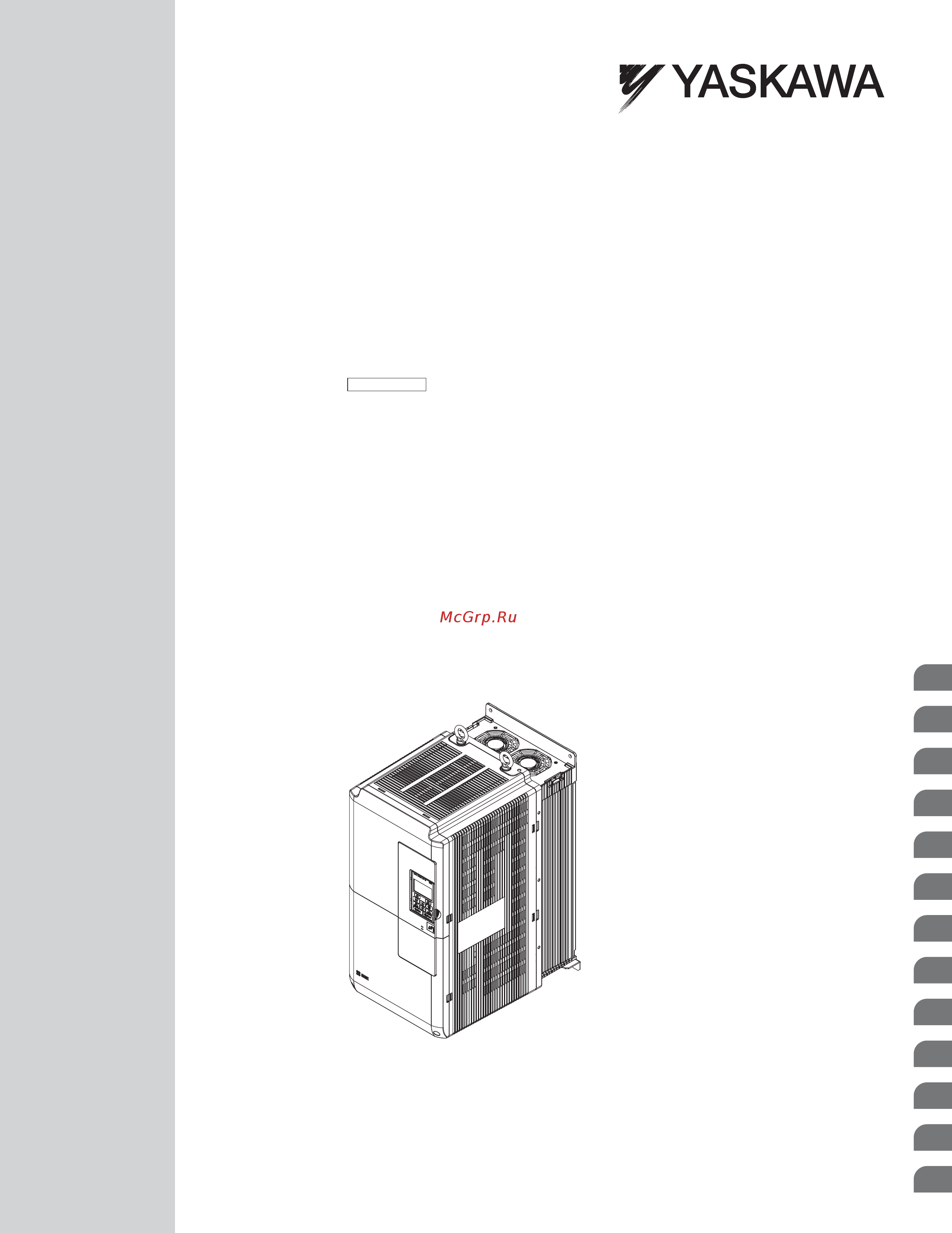
- Two types of enclosures are offered for u1000 drives ip00 open type enclosure models are designed for installation in an enclosure panel that serves to protect personnel from injury caused by accidentally touching live parts ip20 nema type 1 enclosure models mount to an indoor wall or in an enclosure panel table 1 describes drive enclosures and models 37
- Component names 38
- Ip00 open type enclosure 38
- Three phase ac 200 v class models 2 o 0104a to 2 o 0130a three phase ac 400 v class models 4 o 0096a to 4 o 0124a 39
- Three phase ac 200 v class models 2 o 0154a and 2 o 0192a three phase ac 400 v class models 4 o 0156a and 4 o 0180a 40
- Three phase ac 200 v class models 2 o 0248a three phase ac 400 v class models 4 o 0216a to 4 o 0414a 41
- Ip20 nema type 1 enclosure 42
- Three phase ac 200 v class models 2 o 0028f to 2 o 0081f three phase ac 400 v class models 4 o 0011f to 4 o 0077f 42
- Three phase ac 200 v class models 2 o 0104f and 2 o 0130f three phase ac 400 v class models 4 o 0096f and 4 o 0124f 43
- Component names 44
- Three phase ac 200 v class models 2 o 0154f and 2 o 0192f three phase ac 400 v class models 4 o 0156f and 4 o 0180f 44
- Component names 46
- Front views 46
- Mechanical installation 47
- Caution 48
- Crush hazard 48
- Equipment hazard 48
- Fire hazard 48
- Notice 48
- Section safety 48
- Warning 48
- Notice 49
- Install the drive in an environment matching the specifications in table 2 to help prolong the optimum performance life of the drive 50
- Installation environment 50
- Installation orientation and spacing 50
- Mechanical installation 50
- This section outlines specifications procedures and the environment for proper mechanical installation of the drive 50
- Instructions on installation using the eye bolts and hanging brackets 51
- Single drive installation 51
- Follow the procedure described below when suspending the drive with eye bolts or hanging brackets models 2 o 0028 to 2 o 0130 and 4 o 0011 to 4 o 0124 52
- Gradually take up the slack in the wires and hoist the drive after the wires are stretched tight 52
- Horizontal suspension of drive models 2 o 0154 to 2 o 0248 and 4 o 0156 to 4 o 0414 52
- Mechanical installation 52
- Pass wire through the holes of the two eye bolts 52
- To make a wire hanger or frame for use when lifting the drive with a crane lay the drive in a horizontal position and pass a wire through the hanging brackets 52
- Vertical suspension of the drive 52
- Digital operator remote usage 53
- Remote operation 53
- Digital operator remote installation 54
- Mechanical installation 54
- The digital operator mounts to an enclosure two different ways external face mount installs the operator outside the enclosure panel internal flush mount installs the operator inside the enclosure panel 54
- Cut an opening in the enclosure panel for the digital operator as shown in figure 2 1 55
- External face mount 55
- Mechanical installation 55
- Position the digital operator so the display faces outwards and mount it to the enclosure panel as shown in figure 2 0 55
- An internal flush mount requires an installation support set that must be purchased separately contact a yaskawa representative to order an installation support set and mounting hardware figure 2 2 illustrates how to attach the installation support set a 56
- Cut an opening in the enclosure panel for the digital operator as shown in figure 2 3 56
- Figure 2 2 internal flush mount installation 56
- Figure 2 3 panel cut out dimensions internal flush mount installation 56
- Internal flush mount 56
- Mechanical installation 56
- Mount the digital operator to the installation support 56
- Mount the installation support set and digital operator to the enclosure panel 56
- Note use a gasket between the enclosure panel and the digital operator in environments with a significant amount of dust or other airborne debris 56
- Yaskawa electric siep c710636 04c u1000 industrial matrix drive technical manual 56
- Exterior and mounting dimensions 57
- Mechanical installation 57
- Ip00 enclosure drives 58
- Mechanical installation 58
- Table 2 dimensions for ip00 enclosure 200 v class 58
- Yaskawa electric siep c710636 04c u1000 industrial matrix drive technical manual 58
- Mechanical installation 59
- Table 2 dimensions for ip00 enclosure 400 v class 59
- Yaskawa electric siep c710636 04c u1000 industrial matrix drive technical manual 59 59
- Ip20 nema type 1 enclosure drives 60
- Mechanical installation 60
- Table 2 dimensions for ip20 nema type 1 enclosure 200 v class 60
- Yaskawa electric siep c710636 04c u1000 industrial matrix drive technical manual 60
- Mechanical installation 61
- Table 2 dimensions for ip20 nema type 1 enclosure 400 v class 61
- Yaskawa electric siep c710636 04c u1000 industrial matrix drive technical manual 61 61
- Mechanical installation 62
- This page intentionally blank 62
- Electrical installation 63
- Danger 64
- Electrical shock hazard 64
- Fire hazard 64
- Section safety 64
- Warning 64
- Caution 65
- Notice 65
- Warning 65
- Connect the drive and peripheral devices as shown in figure 3 it is possible to set and run the drive via the digital operator without connecting digital i o wiring this section does not discuss drive operation refer to start up programming operation on page 107 for instructions on operating the drive 66
- Standard connection diagram 66
- A a b b z z 67
- Control circuit 67
- Dip switch s1 a2 volt curr sel 67
- Figure 3 drive standard connection diagram example model 2 o 0028 67
- Gfci mccb r 67
- Jumper s3 h1 h2 sink source sel 67
- Jumper s5 am fm volt curr selection 67
- Main circuit 67
- Option 67
- Shielded line twisted pair shielded line main circuit terminal control circuit terminal 67
- Standard connection diagram 67
- Three phase power supply 240 to 500 v 50 60 hz depending on model capacity 67
- Yaskawa electric siep c710636 04c u1000 industrial matrix drive technical manual 67 67
- Standard connection diagram 68
- Figure 3 connecting main circuit terminals 69
- Main circuit connection diagram 69
- Refer to figure 3 when wiring the main circuit of the drive connections may vary based on drive capacity the dc power supply for the main circuit also provides power to the control circuit 69
- Yaskawa electric siep c710636 04c u1000 industrial matrix drive technical manual 69 69
- Figure 3 to figure 3 show the different main circuit terminal arrangements for the drive capacities use table 3 to determine the correct figure based on drive model 70
- Terminal block configuration 70
- Terminal block configuration 71
- Terminal block configuration 72
- Models 2 0028 to 2 0130 and 4 0011 to 4 0124 73
- Models 2 o 0028 to 2 o 0130 and 4 o 0011 to 4 o 0124 73
- Terminal cover 73
- Models 2 0154 to 2 0248 and 4 0156 to 4 0414 74
- Connect the ground wiring first then the main circuit wiring and finally the control circuit wiring 75
- Terminal cover 75
- Digital operator and front cover 76
- Reattaching the digital operator 76
- Removing reattaching the digital operator 76
- Removing reattaching the front cover 76
- Removing the digital operator 76
- Removing the front cover 76
- Digital operator and front cover 77
- Loosen the installation screw on the front cover 77
- Models 2 o 0154 to 2 o 0248 and 4 o 0156 to 4 o 0414 77
- Remove the terminal cover and the digital operator 77
- Unhook the left side of the front cover then swing the left side towards you as shown in figure 3 9 until the cover comes off 77
- Use a straight edge screwdriver to loosen the hooks on each side of the cover that hold it in place 77
- Reattaching the front cover 78
- Attaching the top protective cover 79
- Removing the top protective cover 79
- Top protective cover 79
- Insulation caps or sleeves 80
- Main circuit protective cover 80
- Main circuit terminal functions 80
- Main circuit wiring 80
- Protecting main circuit terminals 80
- Main circuit wire gauges and tightening torque 81
- Three phase 200 v class 81
- Main circuit wiring 82
- Main circuit wiring 83
- Three phase 400 v class 83
- Main circuit wiring 84
- Main circuit terminal and motor wiring 85
- Main circuit wiring 85
- This section outlines the various steps precautions and checkpoints for wiring the main circuit terminals and motor terminals 85
- Cable length between drive and motor 86
- Follow the precautions below when wiring the ground for one drive or a series of drives 86
- Ground wiring 86
- Main circuit wiring 86
- Refer to figure 3 5 when using multiple drives do not loop the ground wire 86
- Voltage drop along the motor cable may cause reduced motor torque when the wiring between the drive and the motor is too long especially at low frequency output this can also be a problem when motors are connected in parallel with a fairly long motor cable drive output current will increase as the leakage current from the cable increases an increase in leakage current may trigger an overcurrent situation and weaken the accuracy of the current detection adjust the drive carrier frequency according to table 3 if the motor wiring distance exceeds 100 m because of the system configuration reduce the ground currents refer to c6 02 carrier frequency selection on page 203 86
- Wire the main circuit terminals after the terminal board has been properly grounded models 2 o 0028 to 2 o 0081 and 4 o 0011 to 4 o 0077 have a cover placed over terminals p1 and n1 prior to shipment to help prevent miswiring use wire cutters to cut away covers as needed for terminals 86
- Wiring the main circuit terminal 86
- Main circuit connection diagram 87
- Main circuit wiring 87
- Refer to main circuit connection diagram on page 69 when wiring terminals on the main power circuit of the drive 87
- Control circuit connection diagram 88
- Control circuit terminal block functions 88
- Control circuit wiring 88
- Input terminals 88
- Control circuit wiring 89
- Output terminals 89
- Serial communication terminals 89
- Table 3 lists the output terminals on the drive text in parenthesis indicates the default setting for each multi function output 89
- Control circuit wiring 90
- Ferrule type wire terminals 90
- Select appropriate wire type and gauges from table 3 for simpler and more reliable wiring use crimp ferrules on the wire ends refer to table 3 0 for ferrule terminal types and sizes 90
- Terminal configuration 90
- The control circuit terminals are arranged as shown in figure 3 7 90
- Wire size and torque specifications 90
- Yaskawa recommends using crimpfox 6 a crimping tool manufactured by phoenix contact to prepare wire ends with insulated sleeves before connecting to the drive see table 3 0 for dimensions 90
- Control circuit wiring 91
- This section describes the proper procedures and preparations for wiring the control terminals 91
- Wire the control circuit only after terminals have been properly grounded and main circuit wiring is complete refer to terminal board wiring guide on page 91 for details prepare the ends of the control circuit wiring as shown in figure 3 1 refer to wire gauges on page 90 connect control wires as shown in figure 3 9 and figure 3 0 91
- Wiring the control circuit terminal 91
- Control circuit wiring 92
- Switches and jumpers on the terminal board 92
- The terminal board is equipped with several switches used to adapt the drive i os to the external control signals figure 3 2 shows the location of these switches refer to control i o connections on page 94 for setting instructions 92
- When setting the frequency by analog reference from an external potentiometer use shielded twisted pair wires preparing wire ends as shown in figure 3 1 and connect the shield to the ground terminal of the drive 92
- Control circuit wiring 93
- Figure 3 2 locations of jumpers and switches on the terminal board 93
- Jumper s5 terminal am fm signal selection 93
- Yaskawa electric siep c710636 04c u1000 industrial matrix drive technical manual 93 93
- Control i o connections 94
- Sinking sourcing mode for digital inputs 94
- Use the wire jumper between terminals sc and sp or sc and sn to select between sink mode source mode or external power supply for the digital inputs s1 to s8 as shown in table 3 1 default sink mode internal power supply 94
- Sinking sourcing mode selection for safe disable inputs 95
- Using power from the pulse output terminal source mode 95
- Using the pulse train output 95
- Control i o connections 96
- Terminal a2 can be used to input either a voltage or a current signal select the signal type using switch s1 as explained in table 3 3 set parameter h3 09 accordingly as shown in table 3 4 refer to switches and jumpers on the terminal board on page 92 for locating switch s1 96
- Terminal a2 input signal selection 96
- Terminal a3 analog ptc input selection 96
- Terminal a3 can be configured either as multi function analog input or as ptc input for motor thermal overload protection use switch s4 to select the input function as described in table 3 5 refer to switches and jumpers on the terminal board on page 92 for locating switch s4 96
- The high voltage level of the pulse output signal depends on the external voltage applied the voltage must be between 12 and 15 vdc the load resistance must be adjusted so that the current is lower than 16 ma 96
- Using external power supply sink mode 96
- Control i o connections 97
- Memobus modbus termination 97
- Slide switch s6 selects n c or n o as the state of the dm and dm terminals for edm output 97
- Terminal am fm signal selection 97
- Terminal dm and dm output signal selection 97
- The signal type for terminals am and fm can be set to either voltage or current output using jumper s5 on the terminal board as explained in table 3 6 when changing the setting of jumper s5 parameters h4 07 and h4 08 must be set accordingly the default selection is voltage output for both terminals refer to switches and jumpers on the terminal board on page 92 for locating jumper s5 97
- This drive is equipped with a built in termination resistor for the rs 422 rs 485 communication port dip switch s2 enables or disabled the termination resistor as shown in table 3 8 the off position is the default the termination resistor should be placed to the on position when the drive is the last in a series of slave drives refer to switches and jumpers on the terminal board on page 92 to locate switch s2 97
- Connect to a pc 98
- Emc filter 99
- Enable the internal emc filter 99
- Emc filter 100
- Emc filter 101
- Emc filter 102
- Controller 103
- Drive 1 103
- Drive 2 103
- Drive ready 103
- Drive ready stop 103
- External interlock 103
- Fault 1 103
- Fault 2 103
- Fault output 103
- Fault2 103
- Operation circuit 103
- Operation ready 103
- Ready 1 103
- Ready 2 103
- Ready1 ready2 fault1 103
- Note close mc1 mcn before operating the drive mc1 mcn cannot be switched off during run 104
- Wiring checklist 104
- Yaskawa electric siep c710636 04c u1000 industrial matrix drive technical manual 104
- Wiring checklist 105
- Yaskawa electric siep c710636 04c u1000 industrial matrix drive technical manual 105 105
- This page intentionally blank 106
- Wiring checklist 106
- Start up programming operation 107
- Danger 108
- Electrical shock hazard 108
- Section safety 108
- Warning 108
- Digital operator keys and displays 109
- Using the digital operator 109
- Lcd display 110
- Using the digital operator 110
- Alarm alm led displays 111
- Lo re led and run led indications 111
- Using the digital operator 111
- Drive mod 112
- Fwd jog 112
- Fwd jog fwd jog 112
- Menu structure for digital operator 112
- Programming mode 112
- Using the digital operator 112
- Navigating the drive and programming modes 113
- The drive and programming modes 113
- Changing parameter settings or values 114
- Drive mode details 114
- Fwd jog 114
- Left right 114
- Mode prg 114
- Press to select local 114
- Press until the frequency reference changes to 006 0 hz 114
- Programming 114
- Programming mode details 114
- The drive and programming modes 114
- The following actions are possible in the drive mode run and stop the drive monitor the operation status of the drive frequency reference output frequency output current output voltage etc view information on an alarm view a history of alarms that have occurred figure 4 illustrates how to change the frequency reference from f 0 0 0 hz to f 6 0 6 hz while in the drive mode this example assumes the drive is set to local 114
- The following actions are possible in the programming mode parameter setting mode access and edit all parameter settings verify menu view a list of parameters that have been changed from the default values setup group access a list of commonly used parameters to simplify setup refer to simplified setup using the setup group on page 117 auto tuning mode automatically calculate and set motor parameters to optimize drive performance 114
- This example explains changing c1 02 deceleration time 1 from 10 seconds to 20 seconds 114
- The drive and programming modes 115
- The drive and programming modes 116
- The following example is a continuation of the steps above here parameter c1 02 is accessed using the verify menu and is changed again from 10 s to 20 s to check the list of edited parameters 116
- The verify menu lists edited parameters from the programming mode or as a result of auto tuning the verify menu helps determine which settings have been changed and is particularly useful when replacing a drive if no settings have been changed the verify menu will read none the verify menu also allows users to quickly access and re edit any parameter settings that have been changed 116
- Verifying parameter changes verify menu 116
- Data fwd 117
- Entry accepted 117
- Fref ai 117
- Fwd jog 117
- Mode prg 117
- Quick setting 117
- Simplified setup using the setup group 117
- U1 01 0 0hz 117
- U1 02 0 0hz u1 03 0 0a 117
- Using the setup group 117
- It is possible to switch between local and remote modes using one of the digital input terminals s1 through s8 set the corresponding parameter h1 oo to 1 setting h1 oo to 1 disables the lo re key on the digital operator refer to h1 multi function digital inputs on page 246 for details 118
- Local mode is when the drive is set to accept the run command from the digital operator run key remote mode is when the drive is set to accept the run command from an external device i e input terminals or serial communications 118
- Setup group parameters 118
- Switch the operation between local and remote using the lo re key on the digital operator or via a digital input 118
- Switching between local and remote 118
- Table 4 lists the parameters available by default in the setup group selecting an application preset in parameter a1 06 or from the application selection menu of the setup group automatically changes the parameters selected for the setup group refer to application selection on page 127 for more information use the programming mode to access parameters not displayed in the setup group 118
- The drive and programming modes 118
- Using input terminals s1 through s8 to switch between local and remote 118
- Using the lo re key on the digital operator 118
- Start up flowcharts 119
- These flowcharts summarize steps required to start the drive use the flowcharts to determine the most appropriate start up method for a given application the charts are quick references to help familiarize the user with start up procedures 119
- Figure 4 basic start up 120
- Flowchart a basic start up and motor tuning 120
- Flowchart a in figure 4 describes a basic start up sequence that varies slightly depending on the application use the drive default parameter settings in simple applications that do not require high precision 120
- Note 1 execute stationary auto tuning for line to line resistance if the drive has been auto tuned and then moved to a different location where the motor cable length exceeds 50 m 2 perform auto tuning again after installing an ac reactor or other such components to the output side of the drive 120
- Start up flowcharts 120
- Yaskawa electric siep c710636 04c u1000 industrial matrix drive technical manual 120
- Flowchart a1 in figure 4 describes simple motor setup for v f control with or without pg feedback v f control is suited for more basic applications such as fans and pumps this procedure illustrates energy savings and speed estimation speed search 121
- Start up flowcharts 121
- Subchart a 1 simple motor setup using v f control 121
- Flowchart a2 in figure 4 0 describes the setup procedure for high performance with open loop vector control or closed loop vector control which is appropriate for applications requiring high starting torque and torque limits 122
- Start up flowcharts 122
- Subchart a 2 high performance operation using olv or clv 122
- Asr gain tuning automatically performs inertia tuning and sets parameters related to the feed forward function 123
- Figure 4 0 flowchart a2 high performance operation using olv or clv 123
- Start up flowcharts 123
- Start up programming operation 123
- Yaskawa electric siep c710636 04c u1000 industrial matrix drive technical manual 123 123
- Flowchart a3 in figure 4 1 describes the setup procedure for running a pm motor in open loop vector control pm motors can be used for more energy efficient operation in reduced or variable torque applications 124
- Start up flowcharts 124
- Subchart a 3 operation with permanent magnet motors 124
- Asr gain tuning automatically performs inertia tuning and sets parameters related to the feed forward function 125
- Figure 4 1 operation with permanent magnet motors 125
- Start up flowcharts 125
- Start up programming operation 125
- Yaskawa electric siep c710636 04c u1000 industrial matrix drive technical manual 125 125
- Powering up the drive 126
- Powering up the drive and operation status display 126
- Status display 126
- Application selection 127
- Setting 1 water supply pump application 127
- Application selection 128
- Setting 2 conveyor application 128
- Setting 3 exhaust fan application 128
- Application selection 129
- Setting 4 hvac fan application 129
- Setting 5 air compressor application 129
- Auto tuning 130
- Auto tuning for induction motors 130
- Types of auto tuning 130
- Auto tuning 131
- Auto tuning for permanent magnet motors 131
- Automatically sets the v f pattern and motor parameters e1 oo and e5 oo when a pm motor is used additionally the feature also sets some f1 oo parameters for speed feedback detection in closed loop vector 131
- Auto tuning 132
- Dependent upon t2 13 setting 132
- Figure 4 2 motor nameplate example 132
- Table 4 8 auto tuning input data 132
- Table 4 8 lists the data that must be entered for auto tuning make sure the data is available before starting auto tuning the necessary information is usually listed on the motor nameplate or in the motor test report provided by the motor manufacturer refer to subchart a 3 operation with permanent magnet motors on page 124 for details on the auto tuning process and selection 132
- Yaskawa electric siep c710636 04c u1000 industrial matrix drive technical manual 132
- Basic auto tuning preparations 133
- Before auto tuning the drive 133
- Inertia tuning and speed control loop auto tuning 133
- Auto tuning 134
- Decouple the load from the motor to achieve optimal performance from rotational auto tuning rotational auto tuning is best suited for applications requiring high performance over a wide speed range if it is not possible to decouple the motor and load reduce the load so it is less than 30 of the rated load performing rotational auto tuning with a higher load will set motor parameters incorrectly and can cause irregular motor rotation ensure the motor mounted brake is fully released if installed connected machinery should be allowed to rotate the motor 134
- Notes on rotational auto tuning 134
- Notes on stationary auto tuning 134
- Perform when using a vector control mode and rotational auto tuning cannot be performed check the area around the motor to ensure that nothing will accidentally cause the motor to rotate during the auto tuning process use stationary auto tuning 3 when the motor test report is not available use stationary auto tuning 2 when the motor test report is available 134
- Stationary auto tuning 2 134
- Stationary auto tuning 3 134
- Stationary auto tuning 3 can be used in either olv or clv control by setting t1 01 to 5 and entering the input data from the motor nameplate pressing the run key stops the motor for approximately one minute to automatically calculate the necessary motor parameters motor parameters e2 02 and e2 03 are set automatically when using the motor for the first time in drive mode after auto tuning has been performed after performing stationary auto tuning 3 make sure the following conditions are met and use the following procedures to perform the operation in test mode 134
- Stationary auto tuning modes analyze motor characteristics by injecting current into the motor for approximately one minute 134
- Auto tuning interruption and fault codes 135
- Notes on inertia tuning and asr gain auto tuning 135
- After selecting the type of auto tuning enter the data required from the motor nameplate 136
- Auto tuning 136
- Auto tuning operation example 136
- Enter data from the motor nameplate 136
- Selecting the type of auto tuning 136
- The following example demonstrates rotational auto tuning when using olv a1 02 2 and clv a1 02 3 136
- Starting auto tuning 137
- T1 00 motor 1 motor 2 selection 137
- T1 parameter settings during induction motor auto tuning 137
- Auto tuning 138
- Auto tuning automatically sets parameters e3 oo and e4 oo for motor 2 make sure that motor 2 is connected to the drive for auto tuning 138
- Sets the motor rated current according to the motor nameplate value set the motor rated current between 50 and 100 of the drive rated current for optimal performance in olv or clv enter the current at the motor base speed 138
- Sets the motor rated frequency according to the motor nameplate value if a motor with an extended speed range is used or the motor is used in the field weakening area enter the maximum frequency to e1 04 e3 04 for motor 2 after auto tuning is complete 138
- Sets the motor rated power according to the motor nameplate value 138
- Sets the motor rated voltage according to the motor nameplate value enter the voltage base speed here if the motor is operating above base speed enter the voltage needed to operate the motor under no load conditions at rated speed to t1 03 for better control precision around rated speed when using a vector control mode the no load voltage can usually be found in the motor test report available from the manufacturer if the motor test report is not available enter approximately 85 of the rated voltage printed on the motor nameplate this may increase the output current and reduce the overload margin 138
- Sets the type of auto tuning to be used refer to auto tuning for induction motors on page 130 for details on the different types of auto tuning 138
- T1 01 auto tuning mode selection 138
- T1 02 motor rated power 138
- T1 03 motor rated voltage 138
- T1 04 motor rated current 138
- T1 05 motor base frequency 138
- Parameter settings during pm motor auto tuning t2 139
- T1 06 number of motor poles 139
- T1 07 motor base speed 139
- T1 08 pg number of pulses per revolution 139
- T1 09 motor no load current 139
- T1 10 motor rated slip 139
- T1 11 motor iron loss 139
- T2 01 pm motor auto tuning mode selection 139
- Auto tuning 140
- If the drive is operating a yaskawa pm motor from the smra ssr1 or sst4 series enter the motor code in t2 02 to automatically set parameters t2 03 through t2 14 if the drive is operating a specialized motor or a motor designed by a manufacturer other than yaskawa set t2 02 to ffff and enter the data from the motor nameplate or the motor test report as prompted only the designated pm motor codes may be entered the pm motor codes accepted by the drive will differ depending on the selected control mode refer to e5 pm motor settings on page 230 for motor codes 140
- Selects the type of pm motor the drive will operate 140
- Sets the motor rated voltage 140
- Specifies the motor rated power in kilowatts 140
- T2 02 pm motor code selection 140
- T2 03 pm motor type 140
- T2 04 pm motor rated power 140
- T2 05 pm motor rated voltage 140
- Auto tuning 141
- Enter the d axis inductance per motor phase 141
- Enter the motor base frequency in hz 141
- Enter the motor rated current in amps 141
- Enter the motor rated speed in r min 141
- Enter the motor stator resistance per motor phase 141
- Enter the number of motor poles 141
- Enter the q axis inductance per motor phase 141
- Selects the units used for setting the induced voltage coefficient 141
- T2 06 pm motor rated current 141
- T2 07 pm motor base frequency 141
- T2 08 number of pm motor poles 141
- T2 09 pm motor base speed 141
- T2 10 pm motor stator resistance 141
- T2 11 pm motor d axis inductance 141
- T2 12 pm motor q axis inductance 141
- T2 13 induced voltage constant unit selection 141
- Auto tuning 142
- Enter the amplitude of the test signal applied to the motor during inertia tuning although this setting rarely needs to be changed decrease the setting if a large load inertia causes problems during inertia tuning adjust t3 02 if a fault occurs when t3 01 is set to a low value 142
- Enter the motor induced voltage constant ke 142
- Enter the number of pulses from the pg encoder per motor rotation set the actual number of pulses for one full motor rotation 142
- Parameter settings during inertia and speed control loop auto tuning t3 142
- Sets the amount of compensation or offset in 0 degree units to fine tune the home position perform z pulse tuning when the amount of offset needed for the z pulse is unknown or if the pg encoder is replaced 142
- Sets the amount of pull in current used to tune the d axis and q axis inductance set as a percentage of the motor rated current 142
- Sets the frequency of the test signal applied to the motor during inertia tuning although this setting rarely needs to be changed increasing the value may be beneficial when working with high inertia loads 142
- T2 14 pm motor induced voltage constant ke 142
- T2 15 pull in current level for pm motor tuning 142
- T2 16 pg number of pulses per revolution for pm motor tuning 142
- T2 17 encoder z pulse offset δθ 142
- T3 01 inertia tuning frequency reference 142
- T3 02 inertia tuning reference amplitude 142
- These tuning methods apply a sine wave test signal to the system the drive estimates the system inertia by the measuring the response and automatically sets the parameters listed in table 4 2 142
- Auto tuning 143
- Enter the inertia of the motor this value is used to determine the load inertia using the test signal response the default setting is for a yaskawa standard motor as listed in the motor inertia table 143
- Sets the response frequency reciprocal of the step response time constant of the system or the connected machine the drive uses this value and the load inertia to fine tune the speed control loop gain c5 01 asr gain 1 oscillation may result if the value input here is higher than the actual response frequency of the system 143
- T3 03 motor inertia 143
- T3 04 asr response frequency 143
- Before starting the motor 144
- During operation 144
- No load operation instructions 144
- No load operation test run 144
- No load operation test run 145
- Start up programming operation 145
- Step display result 145
- The drive should operate normally press 145
- To stop the motor run flashes during deceleration to stop until the motor comes to a complete stop 145
- Yaskawa electric siep c710636 04c u1000 industrial matrix drive technical manual 145 145
- Checklist before operation 146
- Operating the motor under loaded conditions 146
- Precautions for connected machinery 146
- Test run with load connected 146
- Test run with the load connected 146
- Backing up parameter values o2 03 147
- Parameter access level a1 01 147
- Password settings a1 04 a1 05 147
- Verifying parameter settings and backing up changes 147
- Copy function 148
- Check the items that correspond to the control mode being used 149
- Review the checklist before performing a test run check each item that applies 149
- Test run checklist 149
- Test run checklist 150
- Parameter details 151
- A initialization 152
- A1 00 language selection 152
- A1 01 access level selection 152
- A1 02 control method selection 152
- A1 initialization 152
- A1 03 initialize parameters 153
- A initialization 154
- A1 04 a1 05 password and password setting 154
- Parameter a1 04 enters the password when the drive is locked parameter a1 05 is a hidden parameter that sets the password 154
- The parameters shown in table 5 will not be reset when the drive is initialized by setting a1 03 2220 or 3330 although the control mode in a1 02 is not reset when a1 03 is set to 2220 or 3330 it may change when an application preset is selected 154
- The user can set a password in parameter a1 05 to restrict access to the drive the password must be entered to a1 04 to unlock parameter access i e parameter setting a1 04 must match the value programmed into a1 05 the following parameters cannot be viewed or edited until the value entered to a1 04 correctly matches the value set to a1 05 a1 01 a1 02 a1 03 a1 06 and a2 01 through a2 33 the instructions below demonstrate how to set password 1234 an explanation follows on how to enter that password to unlock the parameters 154
- A initialization 155
- A initialization 156
- A1 06 application preset 156
- A1 07 driveworksez function selection 156
- And scroll to a1 02 156
- Drive returns to the parameter display 156
- Enables and disables the driveworksez program inside the drive 156
- Key use 156
- Note 1 parameter settings can be edited after entering the correct password 2 performing a 2 wire or 3 wire initialization resets the password to 0000 156
- Several application presets are available to facilitate drive setup for commonly used applications selecting one of these application presets automatically assigns functions to the input and output terminals and sets a predefined group of parameters to values appropriate for the selected application in addition the parameters most likely to be changed are assigned to the group of user parameters a2 01 through a2 16 user parameters are part of the setup group which provides quicker access by eliminating the need to scroll through multiple menus refer to application selection on page 127 for details on parameter a1 06 156
- Step display result 156
- The display automatically returns to the parameter display 156
- To change the value if desired though changing the control mode at this point is not typically done 156
- To display the value set to a1 02 156
- To enter the password 156
- To return to the previous display without saving changes 156
- To save the new password 156
- To save the setting or press 156
- To scroll to a1 04 156
- Yaskawa electric siep c710636 04c u1000 industrial matrix drive technical manual 156
- A2 01 to a2 32 user parameters 1 to 32 157
- A2 33 user parameter automatic selection 157
- A2 user parameters 157
- B application 158
- B1 01 frequency reference selection 1 158
- B1 operation mode selection 158
- B application 159
- B1 02 run command selection 1 159
- Determines the run command source 1 in the remote mode 159
- Set b1 01 to 4 and set h6 01 to 0 set the h6 02 to the pulse train frequency value that equals 100 of the frequency reference enter a pulse train signal to terminal rp and check for the correct frequency reference on the display 159
- The frequency reference input can be switched between the analog terminals a1 a2 and a3 using multi speed inputs refer to multi step speed selection on page 205 for details on using this function 159
- This setting requires a pulse train signal to terminal rp to provide the frequency reference follow the directions below to verify that the pulse signal is working properly 159
- This setting requires entering the frequency reference via an option board plugged into connector cn5 a on the drive control board consult the option board manual for instructions on integrating the drive with the communication system 159
- This setting requires entering the frequency reference via the rs 485 rs 422 serial communications port control terminals r r s s refer to memobus modbus configuration on page 560 for instructions 159
- This setting requires entering the run command via the digital input terminals using one of following sequences 2 wire sequence 1 159
- This setting requires entering the run command via the digital operator run key and also illuminates the lo re indicator on the digital operator 159
- B1 03 stopping method selection 160
- B application 161
- Clv and clv pm a1 02 3 7 161
- For these control modes parameter b2 01 sets the starting frequency for zero speed control not position lock at stop when the output frequency falls below the setting of b2 01 zero speed control is enabled for the time set in parameter b2 04 161
- Setting 1 coast to stop 161
- Setting 2 dc injection braking to stop 161
- When the run command is removed the drive will enter baseblock turn off its output for the momentary power loss minimum baseblock time l2 03 when the minimum baseblock time has expired the drive will inject the amount dc injection braking is set in parameter b2 02 into the motor windings to brake the motor the stopping time in dc injection braking to stop is significantly faster compared to coast to stop 161
- When the run command is removed the drive will shut off its output and the motor will coast uncontrolled deceleration to stop the stopping time is determined by the inertia and the friction in the driven system 161
- B application 162
- Dc injection braking time is determined by the value set to b2 04 and the output frequency at the time the run command is removed it can be calculated by 162
- Figure 5 coast to stop with timer 162
- Figure 5 dc injection braking time depending on output frequency 162
- Figure 5 dc injection braking to stop 162
- Note if an overcurrent oc fault occurs during dc injection braking to stop lengthen the momentary power loss minimum baseblock time l2 03 until the fault no longer occurs 162
- Setting 3 coast to stop with timer 162
- The wait time t is determined by the output frequency when the run command is removed and by the active deceleration time 162
- When the run command is removed the drive will turn off its output and the motor will coast to stop the drive will not start if a run command is input before the time t c1 02 has expired cycle the run command that was activated during time t after t has expired to start the drive 162
- Yaskawa electric siep c710636 04c u1000 industrial matrix drive technical manual 162
- B application 163
- B1 04 reverse operation selection 163
- B1 05 action selection below minimum output frequency clv and clv pm 163
- Drive disregards a reverse run command or a negative frequency reference 163
- Enables and disables reverse operation for some applications reverse motor rotation is not appropriate and may cause problems e g air handling units pumps etc 163
- Possible to operate the motor in both forward and reverse directions 163
- Sets the operation when the frequency reference is lower than the minimum output frequency set in parameter e1 09 163
- The drive adjusts the motor speed following the speed reference even if the frequency reference is below the setting of parameter e1 09 when the run command is removed and the motor speed is smaller than the setting of b2 01 zero speed control not position lock is performed for the time set in parameter b2 04 before the drive output shuts off 163
- The motor starts when the frequency reference exceeds the parameter e1 09 setting when the motor is running and the frequency reference falls below e1 09 the drive output shuts off and the motor coasts when the motor speed falls below the zero speed level set in b2 01 zero speed control is activated for the time set in b2 04 163
- B application 164
- B1 06 digital input reading 164
- B1 06 digital input reading 0 1 1 164
- Defines how the digital inputs are read the inputs are acted upon every 1 ms or 2 ms depending upon the setting 164
- No name setting range default 164
- Setting 0 read once 1 ms scan 164
- Setting 1 read twice 2 ms scan 164
- Setting 2 run at the minimum frequency 164
- Setting 3 zero speed control 164
- The drive applies zero speed control whenever the frequency reference setting is below the value of parameter e1 09 when the run command is removed zero speed control is activated for the time set in b2 04 even if it was already active before 164
- The state of a digital input is read once if the state has changed the input command is immediately processed with this setting the drive responds more quickly to digital inputs but a noisy signal could cause erroneous operation 164
- The state of a digital input is read twice the input command is processed only if the state does not change during the double reading this reading process is slower than the read once process but it is more resistant to noisy signals 164
- When a run command is active and the frequency reference is smaller than the parameter e1 09 setting the drive runs the motor at the speed set in e1 09 when the run command is removed the drive decelerates the motor as soon as the motor speed reaches the zero speed level set in b2 01 zero speed control is activated for the time set in b2 04 164
- B1 07 local remote run selection 165
- B1 08 run command selection while in programming mode 165
- B1 14 phase order selection 165
- B1 15 frequency reference selection 2 165
- A voltage will be output with pwm switching operation regardless of the output frequency 166
- B application 166
- B1 16 run command selection 2 166
- B1 17 run command at power up 166
- B1 21 start condition selection at closed loop vector control 166
- B1 24 commercial power operation switching selection 166
- B1 25 b1 26 commercial power switching output frequency coincidence level non coincidence level 166
- Cycle the run command to start the drive 166
- Determines whether an external run command that is active during power up will start the drive 166
- Enabled when h1 oo 2 and the terminal is closed refer to setting 2 external reference 1 2 selection on page 248 and refer to b1 01 frequency reference selection 1 on page 158 for details 166
- If an external run command is active when the drive is powered up the drive will begin operating the motor after the internal start up process is complete 166
- Selects a condition to start closed loop vector control there is normally no need to change this parameter from the default value 166
- These parameters set the value in 0 hz increments at which commercial power supply switching selection is enabled and disabled 166
- When the deviation between the output frequency and the power supply frequency is less than or equal to the commercial power switching output frequency coincidence level b1 26 the pwm switching operation stops and switches to operation with a direct commercial power supply connection operation with a direct commercial power supply continues until the deviation between the output frequency and the power supply frequency is greater than or equal to the commercial power switching output frequency coincidence non coincidence level b1 25 b1 26 166
- When the output frequency matches the power supply frequency 60 hz the pwm switching operation stops and switches to operation with a direct commercial power supply connection 166
- B2 01 dc injection braking start frequency 167
- B2 02 dc injection braking current 167
- B2 dc injection braking 167
- B2 03 dc injection braking time at start 168
- B2 04 dc injection braking time at stop 168
- B2 08 magnetic flux compensation value 168
- B3 speed search 168
- Current detection speed search 2 b3 24 2 169
- Speed estimation speed search b3 24 1 169
- B3 01 speed search selection at start 170
- Rotation direction detection conditions for backspin 170
- Speed search activation 170
- B application 171
- B3 03 speed search deceleration time 171
- B3 04 v f gain during speed search 171
- B3 05 speed search delay time 171
- B3 06 output current 1 during speed search 171
- B3 08 current control gain during speed search speed estimation type 171
- During speed search the output voltage calculated from the v f pattern is multiplied with this value changing this value can help reduce the output current during speed search 171
- In cases where an output contactor is used between the drive and the motor the contactor must be closed before speed search can be performed this parameter can be used to delay the speed search operation giving the contactor enough time to close completely 171
- Sets the current injected to the motor at the beginning of speed estimation speed search as a factor of the motor rated current set in e2 01 e4 01 for motor 2 if the motor speed is relatively slow when the drive starts to perform speed search after a long period of baseblock it may be helpful to increase the setting value the output current during speed search is automatically limited by the drive rated current 171
- Sets the output frequency reduction ramp the time entered into b3 03 will be the time to decelerate from maximum frequency e1 04 to minimum frequency e1 09 in current detection type 2 speed search the time set in this parameter is used as the acceleration or deceleration time for the output frequency while searching 171
- Sets the proportional gain for the current controller during speed search there is normally no need to change this parameter from the default value 171
- This setting performs speed search when the run command is entered the drive begins running the motor after speed search is complete 171
- This setting starts operating the drive at the minimum output frequency when the run command is entered if external speed search 1 or 2 is already enabled by a digital input the drive will start operating with speed search 171
- B application 172
- B3 10 speed search detection compensation gain 172
- B3 14 bi directional speed search selection 172
- B3 17 speed search restart current level 172
- B3 18 speed search restart detection time 172
- B3 19 number of speed search restarts 172
- B3 24 speed search method selection 172
- Sets how the drive determines the motor rotation direction when performing speed estimation speed search disable this parameter when b3 50 backspin search direction judgment time 1 is set to 0 or longer 172
- Sets the current level at which speed estimation is restarted as a percentage of drive rated current to avoid overcurrent and overvoltage problems since a large current can flow into the drive if the difference between the estimated frequency and the actual motor speed is too big when performing speed estimation 172
- Sets the gain for the detected motor speed of the speed estimation speed search increase the setting only if an overvoltage fault occurs when the drive restarts the motor 172
- Sets the number of times the drive should attempt to find the speed and restart the motor if the number of restart attempts exceeds the value set to b3 19 the ser fault will occur and the drive will stop 172
- Sets the speed search method in v f v f w pg or olv control modes set this parameter to 2 current detection type speed search 2 when b3 50 is 0 or longer 172
- Sets the time for which the current must be above the level set in b3 17 before restarting speed search 172
- The drive detects the motor rotation direction to restart the motor 172
- The drive uses the frequency reference to determine the direction of motor rotation to restart the motor 172
- Activates and deactivates speed search at start in accordance with whether a run command was issued during an undervoltage uv condition function is active when a momentary power loss l2 01 1 or 2 speed search at start b3 01 1 and coasting to a stop b1 03 1 are enabled 173
- B application 173
- B3 25 speed search wait time 173
- B3 27 start speed search select 173
- B3 29 speed search induced voltage level 173
- B3 31 speed search operation current level 1 current detection type 2 173
- B3 32 speed search operation current level 2 current detection 2 173
- B3 33 speed search selection when run command is given during uv 173
- Lower this value in small increments if changes are necessary setting this value too low will prevent the drive from performing speed search there is normally no need to change this parameter from the default value 173
- Selects a condition to activate speed search selection at start b3 01 set this parameter to 1 when using a sequence in which operation starts when the frequency reference exceeds the minimum output frequency while the run command is active 173
- Sets the current level at which to end the speed search for current detection type speed search 2 as a ratio to e2 03 motor no load current the current level is determined for a no load current that is 30 of the rated motor current when the setting value of e2 03 is less than or equal to 30 of the rated motor current 173
- Sets the current level used to limit the output current during current detection type speed search 2 as a ratio to e2 03 motor no load current the current level is determined for a no load current that is 30 of the rated motor current when the setting value of e2 03 is less than or equal to 30 of the rated motor current 173
- Sets the wait time between speed search restarts increase the wait time if problems occur with overcurrent or if an ser fault occurs 173
- B application 174
- B3 50 b3 51 backspin search direction judgment time 1 2 174
- The direction of the speed search is adjusted to allow for backspin when momentary power loss time t is shorter than the time set in b3 50 the search operates according to the direction command when momentary power loss time t is equal to or longer than the time set in b3 51 the search operates from the opposite direction of the direction command when momentary power loss time t is equal to or longer than the time set in b3 50 and shorter than b3 15 baseblock continues until momentary power loss time t exceeds the time set in b3 51 the search then operates from the opposite direction of the direction command 174
- When time t from the momentary power loss to recovery is between the times set for b3 50 and b3 51 operation will not be restarted and the baseblock will continue the drive will stay in baseblock for the time set in b3 51 even after restoring power after the time set in b3 51 passes speed search starts in the opposite direction of the direction command the deceleration time in b3 53 is used for the search frequency and the setting value of the maximum frequency is used as the starting search frequency 174
- When time t from the momentary power loss to recovery is shorter than the setting value of b3 50 speed search is performed in the direction specified by the direction command the deceleration time set in b3 52 is used for the search frequency and the setting value of the maximum frequency is used as the starting search frequency 174
- B application 175
- B3 52 backspin search deceleration time 1 175
- B3 53 backspin search deceleration time 2 175
- Motor speed 175
- Sets the search frequency deceleration rate for a speed search from the opposite direction of the direction command when momentary power loss time t is equal to or longer than the time set in b3 51 175
- Sets the search frequency deceleration rate when searching from the direction command when momentary power loss time t is shorter than the time set in b3 50 set the value lower than the motor deceleration rate during coasting 175
- When time t from the momentary power loss to recovery exceeds the setting value of b3 51 speed search is performed in the opposite direction of the direction command the deceleration time in b3 53 is used for the search frequency and the setting value of the maximum frequency is used as the starting search frequency 175
- B application 176
- B4 01 b4 02 timer function on delay off delay time 176
- B4 01 sets the on delay time for switching the timer output b4 02 sets the off delay time for switching the timer output 176
- B4 03 to b4 08 h2 oo on delay and off delay time 176
- B4 timer function 176
- Sets the length of the delay time for contact outputs to open or close for the related functions set in h2 oo 176
- The timer function is independent of drive operation and can delay the switching of a digital output triggered by a digital input signal and help eliminate chattering switch noise from sensors an on delay and off delay can be set separately to enable the timer function set a multi function input to timer function input h1 oo 18 and set a multi function output to timer output h2 oo 12 only one timer can be used 176
- The timer function switches on when the timer function input closes for longer than the value set to b4 01 the timer function switches off when the timer function input is open for longer than the value set to b4 02 figure 5 2 illustrates the timer function operation 176
- Timer function operation 176
- B5 pid control 177
- D control 177
- I control 177
- P control 177
- Pid operation 177
- Pid setpoint input methods 177
- Using pid control 177
- B application 178
- Input one feedback signal for normal pid control or input two feedback signals can for controlling a differential process value 178
- Input the pid feedback signal from one of the sources listed in table 5 0 178
- Pid feedback input methods 178
- The second pid feedback signal for differential feedback can come from the sources listed in table 5 1 the differential feedback function is automatically enabled when a differential feedback input is assigned 178
- Always 1 when b5 01 3 4 179
- B application 179
- Enable disable reverse operation when pid output is negative 179
- Pid block diagram 179
- Proportional gain b5 02 179
- B application 180
- B5 01 pid function setting 180
- B5 02 proportional gain setting p 180
- B5 03 integral time setting i 180
- B5 04 integral limit setting 180
- B5 05 derivative time d 180
- B5 06 pid output limit 180
- Enables or disables the pid operation and selects the pid operation mode 180
- Sets the maximum output possible from the entire pid controller as a percentage of the maximum frequency e1 04 180
- Sets the maximum output possible from the integral block as a percentage of the maximum frequency e1 04 180
- Sets the p gain applied to the pid input larger values will tend to reduce the error but may cause oscillations if set too high while lower values may allow too much offset between the setpoint and feedback 180
- Sets the time constant used to calculate the integral of the pid input the shorter the integral time set to b5 03 the faster the offset will be eliminated if the integral time is set too short however overshoot or oscillation may occur to turn off the integral time set b5 03 to 0 0 180
- Sets the time the drive predicts the pid input pid feedback signal based on the derivative of the pid input pid feedback longer time settings improve the response but can cause vibrations while shorter time settings reduce the overshoot but reduce controller responsiveness d control is disabled by setting b5 05 to zero seconds 180
- The pid controller is enabled and the pid output builds the frequency reference the pid feedback is d controlled 180
- The pid controller is enabled and the pid output builds the frequency reference the pid input is d controlled 180
- The pid controller is enabled and the pid output is added to the frequency reference the pid feedback is d controlled 180
- The pid controller is enabled and the pid output is added to the frequency reference the pid input is d controlled 180
- A positive pid input causes a decrease in the pid output reverse acting 181
- A positive pid input causes an increase in the pid output direct acting 181
- Applies a gain to the pid output and can be helpful when the pid function is used to trim the frequency reference b5 01 3 or 4 181
- B application 181
- B5 07 pid offset adjustment 181
- B5 08 pid primary delay time constant 181
- B5 09 pid output level selection 181
- B5 10 pid output gain setting 181
- B5 11 pid output reverse selection 181
- Determines whether a negative pid output reverses the direction of drive operation this parameter has no effect when the pid function trims the frequency reference b5 01 3 or 4 and the pid output will not be limited same as b5 11 1 181
- Negative pid output will be limited to 0 and the drive output will be stopped 181
- Negative pid output will cause the drive to run in the opposite direction 181
- Pid feedback loss detection 181
- Reverses the sign of the pid controller output signal normally a positive pid input feedback smaller than setpoint leads to positive pid output 181
- Sets the offset added to the pid controller output as a percentage of the maximum frequency e1 04 181
- Sets the time constant for the filter applied to the output of the pid controller normally change is not required 181
- The pid feedback loss detection function detects broken sensors or broken sensor wiring it should be used when pid control is enabled to prevent critical machine conditions e g acceleration to max frequency caused by a feedback loss feedback loss can be detected in two ways feedback low detection detected when the feedback falls below a certain level for longer than the specified time this function is set up using parameters b5 12 to b5 14 feedback high detection 181
- B5 12 pid feedback loss detection selection 182
- B5 13 pid feedback low detection level 182
- B application 183
- B5 14 pid feedback low detection time 183
- B5 15 pid sleep function start level 183
- B5 16 pid sleep delay time 183
- B5 36 pid feedback high detection level 183
- B5 37 pid feedback high detection time 183
- Pid sleep 183
- Sets the delay time to activate or deactivate the pid sleep function 183
- Sets the feedback level used for pid feedback high detection the pid feedback must exceed this level for longer than the time set to b5 37 before feedback loss is detected 183
- Sets the level that triggers pid sleep the drive goes into sleep mode if the pid output or frequency reference is smaller than b5 15 for longer than the time set to b5 16 the drive resumes operation when the pid output or frequency reference is above b5 15 for longer than the time set to b5 16 183
- Sets the time that the pid feedback has to fall below b5 13 before feedback loss is detected 183
- Sets the time that the pid feedback must exceed the value set to b5 36 before feedback loss is detected 183
- The pid sleep function is active even when pid control is disabled the pid sleep function stops the motor according to the stopping method set to b1 03 the parameters necessary to control the pid sleep function are explained below 183
- The pid sleep function stops the drive when the pid output or the frequency reference falls below the pid sleep operation level for a certain time the drive will resume operating when the pid output or frequency reference rise above the pid sleep operation level for the specified time an example of pid sleep operation appears in the figure below 183
- B application 184
- B5 17 pid accel decel time 184
- B5 18 pid setpoint selection 184
- B5 19 pid setpoint value 184
- B5 20 pid setpoint scaling 184
- B5 34 pid output lower limit 184
- B5 35 pid input limit 184
- Determines the units for the pid setpoint value b5 19 and monitors u5 01 and u5 04 the units for setting and display can be changed with b5 20 184
- Enables or disables parameter b5 19 for pid setpoint 184
- Parameter b5 19 is not used as the pid setpoint 184
- Parameter b5 19 is used as pid setpoint 184
- Parameters b5 38 and b5 39 determine the units and resolution used to display the values the setpoint in b5 19 and pid monitors u1 01 and u1 04 184
- Sets the maximum allowed pid input as a percentage of the maximum output frequency e1 04 parameter b5 35 acts as a bipolar limit 184
- Sets the minimum possible pid controller output as a percentage of the maximum output frequency e1 04 the lower limit is disabled when set to 0 0 184
- The pid acceleration deceleration time is applied on the pid setpoint value when the setpoint changes quickly the normal c1 oo acceleration times reduce the responsiveness of the system as they are applied after the pid output the pid accel decel time helps avoid the hunting and overshoot and undershoot that can result from the reduced responsiveness the pid acceleration deceleration time can be canceled using a digital input programmed for pid sfs cancel h1 oo 34 184
- The setpoint and pid monitors are displayed as a percentage with a resolution of 0 1 184
- The setpoint and pid monitors are displayed in hz with a resolution of 0 1 hz 184
- The setpoint and pid monitors are displayed in r min with a resolution of 1 r min 184
- Used as the pid setpoint if parameter b5 18 1 184
- B application 185
- B5 38 b5 39 pid setpoint user display pid setpoint display digits 185
- B5 40 frequency reference monitor content during pid 185
- B5 47 pid output reverse selection 2 185
- Determines whether a negative pid output reverses the direction of drive operation when the pid function is used to trim the frequency reference b5 01 3 or 4 this parameter has no effect and the pid output will not be limited same as b5 11 1 185
- Monitor u1 01 displays the frequency reference increased or reduced for the pid output 185
- Monitor u1 01 displays the frequency reference value 185
- Negative pid output will be limited to 0 and the drive output will be stopped 185
- Negative pid output will cause the drive to run in the opposite direction 185
- Sets the content of the frequency reference monitor display u1 01 when pid control is active 185
- When parameter b5 20 is set to 3 parameters b5 38 and b5 39 set a user defined display for the pid setpoint b5 19 and pid feedback monitors u5 01 u5 04 parameter b5 38 determines the display value when the maximum frequency is output and parameter b5 39 determines the number of digits the setting value is equal to the number of decimal places 185
- B application 186
- B6 dwell function 186
- Fine tuning pid 186
- Follow the directions below to fine tune pid control parameters 186
- The dwell function temporarily holds the frequency reference at a predefined value for a set time then continues accelerating or decelerating the dwell function helps prevent speed loss when starting and stopping a heavy load with induction motors when running a pm motor in v f control the pause in acceleration allows the pm motor rotor to align with the stator field of the motor and reduce the starting current figure 5 7 illustrates how the dwell function works 186
- B6 01 b6 02 dwell reference dwell time at start 187
- B6 03 b6 04 dwell reference dwell time at stop 187
- B7 01 droop control gain 187
- B7 droop control clv clv pm 187
- Parameter details 187
- Adjusts the responsiveness of droop control reduce the setting if the reaction time is too long and increase the setting if hunting occurs 188
- B application 188
- B7 02 droop control delay time 188
- B7 03 droop control limit selection 188
- B8 01 energy saving control selection 188
- B8 02 energy saving gain olv clv 188
- B8 energy saving 188
- Enables or disables the droop control limit 188
- Enables or disables the energy saving function 188
- Sets the gain level for energy saving a higher value results in lower magnetization of the motor and less energy consumption if the value is set too high the motor may stall 188
- The energy saving feature improves overall system operating efficiency by operating the motor at its most efficient level 188
- B application 189
- B8 03 energy saving control filter time constant olv clv 189
- B8 04 energy saving coefficient value v f v f w pg 189
- B8 05 power detection filter time v f v f w pg 189
- B8 06 search operation voltage limit v f v f w pg 189
- B8 16 energy saving parameter ki for pm motors 189
- B8 17 energy saving parameter kt for pm motors 189
- Determines how often in milliseconds the output power is measured the energy saving function continuously searches out the lowest output voltage to achieve minimum output power reducing this setting increases the response time if the filter time is too short the motor may become unstable with a lighter load 189
- Fine tunes energy saving control the default setting is for a standard yaskawa motor when using a different motor adjust this parameter in 5 increments until output power monitor u1 08 is at the minimum value while running the drive with a light load a low setting results in less output voltage and less energy consumption if the value is set too low the motor may stall the default setting depends on the capacity of the drive 189
- Sets the response time for energy saving a lower value allows for a quicker response however a value that is too low may cause instability 189
- Sets the voltage limit for the speed search optimal output voltage detection as a percentage of the maximum output voltage the drive will keep the output voltage above this level during the search operation to prevent motor stalling 189
- There is normally no need to change this parameter from the default value coefficient to adjust torque linearity set to the ki value specified on the motor nameplate setting e5 01 motor code selection for pm motors to 1 ooo or 2 ooo automatically sets the calculated value this set value cannot be changed if oscillation occurs when energy saving is enabled b8 01 1 check the value displayed in monitor u5 21 if the value displayed differs from the ki value written on the motor nameplate set b8 16 accordingly 189
- There is normally no need to change this parameter from the default value coefficient to adjust torque linearity set to the kt value specified on the motor nameplate setting e5 01 motor code selection for pm motors to 1 ooo or 2 ooo automatically sets the calculated value this set value cannot be changed if oscillation occurs when energy saving is enabled b8 01 1 check the value displayed in monitor u5 22 if the value displayed differs from the kt value written on the motor nameplate set b8 17 accordingly 189
- Adjusts the responsiveness of the zero servo position loop increase the value if the response is too slow and the deviation from the zero position rises too high when load is applied decrease the value if vibrations occur during zero servo operation 190
- B application 190
- B9 01 zero servo gain 190
- B9 02 zero servo completion width 190
- B9 zero servo 190
- Sets the output range of the zero servo completion signal enter the amount of deviation allowable from the desired position to trigger zero servo an output terminal set for zero servo h2 oo 33 will be triggered when the motor reaches the position zero servo plus or minus b9 02 190
- The zero servo function is a position loop that can be used in clv and clv pm control modes to lock the motor at a certain position to activate zero servo mode use a digital input set for h1 oo 72 and the drive will decelerate when this input is closed the drive goes into zero servo mode and holds the current position when the motor speed falls below the level set to parameter b2 01 the drive accelerates when the input assigned to trigger the zero servo function is released and the run command is still present 190
- When zero servo mode is active the deviation between the rotor position and the zero position is displayed in monitor u6 22 monitor value must be divided by 4 to get the deviation in actual encoder pulses a digital output programmed for zero servo complete h2 oo 33 is turned on when the rotor position is within the zero position plus or minus the zero servo completion width set to parameter b9 02 190
- C tuning 191
- C1 acceleration and deceleration times 191
- C tuning 192
- C1 09 fast stop time 192
- C1 09 fast stop time 0 to 6000 s 192
- C1 10 accel decel time setting units 192
- C1 10 accel decel time setting units 0 1 1 192
- Determines the units for the acceleration and deceleration times set to c1 01 through c1 09 using parameter c1 10 192
- No parameter name setting range default 192
- Sets a special deceleration used when a select group of faults occur e g l8 03 overheat pre alarm operation selection or when closing a digital input configured as h1 oo 15 n o input or 17 n c input a momentary closure of the digital input will trigger the fast stop operation it does not have to be closed continuously the drive cannot be restarted after initiating a fast stop operation until after completing deceleration clearing the fast stop input and cycling the run command a digital output programmed for during fast stop h2 oo 4c will be closed as long as fast stop is active 192
- Setting 0 0 1 s units 192
- Switching accel decel times by a frequency level 192
- Switching acceleration and deceleration times by motor selection 192
- The accel decel times are set in 0 1 s units the setting range is 0 0 to 600 0 s c1 10 cannot be set to 0 if any of the parameters c1 01 to c1 09 is set to 600 s or longer 192
- The drive can switch between different acceleration and deceleration times automatically the drive will switch from accel decel time 4 in c1 07 and c1 08 to the default accel decel time in c1 01 and c1 02 c1 05 and c1 06 for motor 2 when the output frequency exceeds the frequency level set to parameter c1 11 when the frequency falls below this level the accel decel times are switched back figure 5 2 shows an operation example 192
- When switching between motor 1 and 2 using a digital input h1 oo 16 parameters c1 01 to c1 04 become accel decel times 1 and 2 for motor 1 while c1 05 to c1 08 become accel decel times 1 and 2 for motor 2 accel decel times 1 and 2 can be switched for each motor using a digital inputs set to h1 oo 7 like shown in table 5 4 192
- C1 11 accel decel time switching frequency 193
- C2 01 to c2 04 s curve characteristics 193
- C2 s curve characteristics 193
- C3 01 slip compensation gain 193
- C3 slip compensation 193
- Adjusts the filter on the output side of the slip compensation function although this parameter rarely needs to be changed adjustments may be necessary in the following situations decrease the setting when the slip compensation response is too slow increase this setting when speed is unstable 194
- C tuning 194
- C3 02 slip compensation primary delay time 194
- C3 03 slip compensation limit 194
- C3 04 slip compensation selection during regeneration 194
- C3 05 output voltage limit operation selection 194
- Determines if the motor flux reference is automatically reduced when output voltage reaches the saturation range 194
- Enables or disables slip compensation during regenerative operation this function does not operate when the output frequency is too low regardless of whether it has been enabled 194
- Sets the upper limit for the slip compensation function as a percentage of the motor rated slip e2 02 194
- Slip compensation is enabled during regenerative operation and at frequencies as low as 2 hz the drive uses the motor rated slip set to e2 02 to automatically calculate the frequency range where compensation will be disabled 194
- Slip compensation is enabled during regenerative operation it will not be active at output frequencies below 6 hz 194
- Slip compensation is not provided depending on the load and mode of operation the actual motor speed will be lower or higher than the frequency reference 194
- The slip compensation limit is constant throughout the constant torque range frequency reference e1 06 in the constant power range frequency reference e1 06 it is increased based on c3 03 and the output frequency as shown in the following diagram 194
- C tuning 195
- C3 21 motor 2 slip compensation gain 195
- C3 22 motor 2 slip compensation primary delay time 195
- C3 23 motor 2 slip compensation limit 195
- C3 24 motor 2 slip compensation selection during regeneration 195
- Functions for motor 2 the same way that c3 02 functions for motor 1 refer to c3 02 slip compensation primary delay time on page 194 for details on adjusting this parameter 195
- Functions for motor 2 the same way that c3 04 functions for motor 1 refer to c3 04 slip compensation selection during regeneration on page 194 for details on adjusting this parameter 195
- If the input power supply voltage is low or the motor has a high voltage rating this function improves the speed precision when moving heavy loads at high speeds when selecting the drive remember that the reduction in flux causes a slightly higher current at high speed when this function is enabled 195
- Improves the speed accuracy for motor 2 and functions in the same way that c3 01 functions for motor 1 adjust this parameter only after setting the motor rated current e4 01 motor rated slip e4 02 and the motor no load current e4 03 refer to c3 01 slip compensation gain on page 193 for details on adjusting this parameter 195
- Sets the upper limit for the slip compensation function as a percentage of the motor rated slip e4 02 195
- The slip compensation limit is constant throughout the constant torque range frequency reference e3 06 in the constant power range frequency reference e3 06 it is increased based on c3 23 and the output frequency as illustrated in figure 5 5 195
- Although c4 02 rarely needs to be changed adjustments may be necessary in the following situations increase this setting if the motor vibrates decrease this setting if the motor responds too slowly to changes in the load 196
- Although this parameter rarely needs to be changed it may be necessary to adjust the torque compensation gain in small steps of 0 5 in the following situations increase this setting when using a long motor cable decrease this setting when motor oscillation occurs adjust c4 01 so the output current does not exceed the drive rated current 196
- C tuning 196
- C4 01 torque compensation gain 196
- C4 02 torque compensation primary delay time 196
- C4 03 torque compensation at forward start olv 196
- C4 04 torque compensation at reverse start olv 196
- C4 torque compensation 196
- Sets the amount of torque at start in the forward direction to improve motor performance during start with a heavy load compensation is applied using the time constant set in parameter c4 05 enable this function when the load pulls the motor in reverse when starting with a forward run command setting 0 disables this feature 196
- Sets the amount of torque reference at start in the reverse direction to improve motor performance during start with heavy load compensation is applied using the torque compensation time set in parameter c4 05 enable this function if the load pulls the motor in the forward direction when starting with a reverse run command setting 0 disables this feature 196
- Sets the delay time used for applying torque compensation 196
- Sets the gain for the torque compensation function 196
- The drive calculates the motor primary voltage loss using the output current and the termination resistor value e2 05 for im motors e5 05 for pm motors and adjusts the output voltage to compensate for insufficient torque at start or when load is applied the effects of this voltage compensation can be increased or decreased using parameter c4 01 196
- The drive controls the motor excitation current d axis current and torque producing current q axis current separately torque compensation affects the torque producing current only c4 01 works as a factor of the torque reference value that builds the torque producing current reference 196
- The torque compensation function compensates for insufficient torque production at start up or when a load is applied 196
- Adjusting the asr parameters 197
- C4 05 torque compensation time constant olv 197
- C4 07 motor 2 torque compensation gain 197
- C5 automatic speed regulator asr 197
- C tuning 198
- Perform the following steps for adjusting asr parameters 198
- The drive is preset to use asr settings c5 01 02 over the entire speed range in clv aolv pm and clv pm if required by the application a second set of asr parameters c5 03 04 can be automatically activated depending on the motor speed or by using a digital input refer to c5 01 c5 03 c5 02 c5 04 asr proportional gain 1 2 asr integral time 1 2 on page 199 perform the following steps for adjusting asr parameters 198
- Use table 5 5 when making adjustments to asr though the parameters listed below are for motor 1 the same changes can be made to the corresponding motor 2 parameters when running a second motor 198
- C tuning 199
- C5 01 c5 03 c5 02 c5 04 asr proportional gain 1 2 asr integral time 1 2 199
- In these control modes parameters c5 03 and c5 04 define the asr gain an integral time at zero speed the settings in c5 01 and c5 02 are used at speeds above the setting in c5 07 c5 07 is set to 0 as the default so that c5 01 and c5 02 are used over the entire speed range refer to c5 07 asr gain switching frequency on page 200 199
- Parameters c5 01 and c5 02 determine the asr characteristics at maximum speed parameters c5 03 and c5 04 determine the characteristics at minimum speed 199
- The gain set in c5 03 can also be activated with a digital input programmed to asr gain switch h1 oo 77 when the terminal is open the drive uses the asr gain level set by the pattern in the figure above when the terminal closes c5 03 is used the integral time set to c5 02 is used to change linearly between these settings the asr gain switch command from a multi function input terminal overrides the switching frequency set to c5 07 199
- These parameter settings will function differently depending on the control mode 199
- These parameters adjust the responsiveness of the asr 199
- C tuning 200
- C5 05 asr limit 200
- C5 06 asr primary delay time constant 200
- C5 07 asr gain switching frequency 200
- C5 08 asr integral limit 200
- C5 12 integral operation during accel decel v f w pg 200
- Determines how fast a continuous speed deviation problem is eliminated a setting that is too long reduces the responsiveness of the speed control a setting that is too short can cause oscillation 200
- Enables integral operation during acceleration and deceleration use integral operation when driving a heavy load or a high inertia load default set c5 12 to 1 to use integral operation for low inertia high performance loads enabling integral operation may cause problems with overshoot at the end of acceleration and deceleration refer to asr setup problems and corrective actions on page 198 to solve such problems 200
- Sets the asr output limit as a percentage of the maximum output frequency e1 04 if the motor rated slip is high the setting might need to be increased to provide proper motor speed control use the asr output monitor u6 04 to determine if asr is working at the limit set in c5 05 if asr is working at the limit make sure the pg pulses f1 01 pg gear teeth f1 12 f1 13 and the pg signal are set correctly before making further changes to c5 05 200
- Sets the filter time constant for the time from the speed loop to the torque command output increase this setting gradually in increments of 0 1 for loads with low rigidity or when oscillation is a problem this parameter rarely needs to be changed 200
- Sets the frequency where the drive should switch between asr proportional gain 1 and 2 c5 01 c5 03 as well as between integral time 1 and 2 c5 02 c5 04 200
- Sets the upper limit for asr as a percentage of the rated load 200
- Switching the proportional gain and integral time in the low or high speed range can help stabilize operation and avoid resonance problems a good switching point is 80 of the frequency where oscillation occurs or at 80 of the target speed refer to c5 01 c5 03 c5 02 c5 04 asr proportional gain 1 2 asr integral time 1 2 on page 199 200
- The higher this setting the faster the speed response although a setting that is too high can lead to oscillation increase this setting with larger loads to minimize the speed deviation 200
- C tuning 201
- C5 17 and c5 18 determine the ratio of the machine inertia to the inertia of the motor being used example setting c5 18 to 2 reflects a load inertia that is twice the motor inertia these parameters are set automatically when inertia tuning and asr tuning are performed in clv and clv pm control modes refer to auto tuning on page 130 for details on auto tuning or enter the data manually 201
- C5 17 c5 18 motor inertia load inertia ratio 201
- C5 21 c5 23 c5 22 c5 24 motor 2 asr proportional gain 1 2 integral time 1 2 201
- C5 25 motor 2 asr limit 201
- C5 26 motor 2 asr primary delay time constant 201
- C5 27 motor 2 asr gain switching frequency 201
- C5 28 motor 2 asr integral limit 201
- Functions for motor 2 the same way that c5 05 functions for motor 1 sets the asr output limit for motor 2 as a percentage of the maximum output frequency e4 04 refer to c5 05 asr limit on page 200 for details 201
- Functions for motor 2 the same way that c5 06 functions for motor 1 sets the filter time constant for the time from the speed loop to the torque command output refer to c5 06 asr primary delay time constant on page 200 for details this parameter rarely needs to be changed 201
- Functions for motor 2 the same way that c5 07 functions for motor 1 sets the frequency for motor 2 to change asr proportional gain 1 and 2 c5 21 c5 23 as well as the integral time 1 and 2 c5 22 c5 24 refer to c5 01 c5 03 c5 02 c5 04 asr proportional gain 1 2 asr integral time 1 2 on page 199 for details 201
- Functions for motor 2 the same way that c5 08 functions for motor 1 sets the upper limit for asr as a percentage of the rated load refer to c5 08 asr integral limit on page 200 for details 201
- Integral operation is always enabled 201
- Integral operation occurs only during constant speed and not during acceleration or deceleration 201
- These parameters function for motor 2 the same way that c5 01 through c5 04 function for motor 1 refer to c5 01 c5 03 c5 02 c5 04 asr proportional gain 1 2 asr integral time 1 2 on page 199 for details 201
- C tuning 202
- C5 32 integral operation during accel decel for motor 2 202
- C5 37 c5 38 motor 2 inertia motor 2 load inertia ratio 202
- C6 01 drive duty mode selection 202
- C6 carrier frequency 202
- Functions for motor 2 the same way that c5 12 functions for motor 1 enables integral operation during acceleration and deceleration refer to c5 12 integral operation during accel decel v f w pg on page 200 for details 202
- Integral operation is always enabled 202
- Integral operation occurs only during constant speed and not during acceleration or deceleration 202
- The drive has two different duty modes from which to select based on the load characteristics the drive rated current overload capacity and maximum output frequency will change depending upon the duty mode selection use parameter c6 01 to select heavy duty hd or normal duty nd for the application refer to heavy duty and normal duty ratings on page 430 for details about the rated current 202
- These parameters function for motor 2 the same way that c5 17 and c5 18 function for motor 1 these parameters are set automatically when inertia tuning and asr tuning are performed for motor 2 in clv and clv pm control modes refer to auto tuning on page 130 for details on auto tuning or enter the data manually 202
- A carrier frequency between the fixed selectable values can be entered in parameter c6 03 when c6 02 is set to f in v f control adjust parameter c6 04 to the same value as c6 03 203
- C tuning 203
- C6 02 carrier frequency selection 203
- C6 03 c6 04 c6 05 carrier frequency upper limit lower limit proportional gain 203
- Guidelines for carrier frequency parameter setup 203
- Sets the switching frequency of the drive output transistors changes to the switching frequency lower audible noise and reduce leakage current 203
- These parameters set a user defined or a variable carrier frequency set c6 02 to f to set the upper and lower limits and the carrier frequency proportional gain 203
- C tuning 204
- C6 09 carrier frequency during rotational auto tuning 204
- C7 43 input voltage offset adjustment 204
- C7 56 power factor control selection 204
- C7 60 output voltage limit mode selection 204
- C7 voltage adjustment 204
- Determines the carrier frequency while performing rotational auto tuning although this parameter rarely needs to be changed when overcurrent problems occur when auto tuning a high frequency motor or low impedance motor it may be helpful to set c6 03 to a high value before setting c6 09 to 1 204
- Enables adjustment of the offset for the input voltage circuit when the control board is replaced changing the value of o2 04 will trigger an ope30 error the input voltage offset must be adjusted when the error occurs if the combination of the control board and drive does not change set this parameter to 0002 offset adjustment not required contact yaskawa or a yaskawa representative if it becomes necessary to replace the control board 204
- In v f control the carrier frequency can be set up to change linearly with the output frequency by setting the upper and lower limits for the carrier frequency and the carrier frequency proportional gain c6 03 c6 04 c6 05 204
- Power factor control improves the input power supply power factor according to the operating conditions this parameter rarely requires adjustment but may be enabled to improve the power factor in the low output region power factor control is not suitable for applications with frequent load fluctuations this function is disabled in high output voltage mode c7 60 1 204
- Sets the mode to limit the output voltage set this parameter to 0 harmonic suppression priority mode to give priority to harmonic suppression the maximum output voltage is automatically limited to suppress harmonics set this parameter to 1 high output voltage mode to give priority to the output voltage over harmonic suppression the effectiveness of harmonic suppression will be reduced because the maximum output voltage will be used 204
- D reference settings 205
- D1 frequency reference 205
- Parameter details 205
- D reference settings 206
- Set h3 06 terminal a3 function selection to 2 auxiliary frequency reference 1 when setting terminal a3 analog input to multi step speed 2 set h3 06 to f through mode when setting d1 02 frequency reference 2 to multi step speed 2 multi step speed 3 set h3 10 terminal a2 function selection to 3 auxiliary frequency reference 2 when setting terminal a2 analog input to multi step speed 3 set h3 10 to f through mode when setting d1 03 frequency reference 3 to multi step speed 3 set h3 09 to 0 and set dip switch s1 on the control circuit terminal board to v voltage when inputting 0 to 10 v to terminal a2 analog input select the different speed references as shown in table 5 8 figure 5 2 illustrates the multi step speed selection 206
- D2 01 frequency reference upper limit 207
- D2 02 frequency reference lower limit 207
- D2 frequency upper lower limits 207
- D reference settings 208
- D2 03 master speed reference lower limit 208
- D3 01 to d3 04 jump frequencies 1 2 3 and jump frequency width 208
- D3 jump frequency 208
- Figure 5 4 shows the relationship between the jump frequency and the output frequency 208
- Sets a lower limit as a percentage of the maximum output frequency that will only affect a frequency reference entered from the analog input terminals a1 a2 or a3 as the master speed reference this is unlike parameter d2 02 which affects all frequency references regardless of their source 208
- The jump frequencies are frequency ranges at which the drive will not operate the drive can be programmed with three separate jump frequencies to avoid operating at speeds that cause resonance in driven machinery if the speed reference falls within a jump frequency dead band the drive will clamp the frequency reference just below the dead band and only accelerate past it when the frequency reference rises above the upper end of the dead band setting parameters d3 01 through d3 03 to 0 hz disables the jump frequency function 208
- D4 01 frequency reference hold function selection 209
- D4 frequency reference hold and up down 2 function 209
- D reference settings 210
- Figure 5 5 frequency reference hold with accel decel hold function 210
- Figure 5 6 up down 2 example with reference from digital operator and d4 01 1 210
- Frequency reference 210
- Output frequency 210
- Up 2 command 210
- Up down 2 with frequency reference from input sources other than the digital operator when a run command is active and the up down 2 command is released for longer than 5 s the bias value will be saved in parameter d4 06 when restarting after the power is switched off the drive will add the value saved in d4 06 as a bias to the frequency reference 210
- Up down the frequency reference value will be saved when the run command or the drive power is switched off the drive will use the frequency reference that was saved when it restarts up down 2 with frequency reference from digital operator when a run command is active and the up down 2 command is released for longer than 5 s the up down 2 bias value is added to the frequency reference and then reset to 0 this new frequency reference is saved and will also be used to restart the drive after the power is cycled 210
- Yaskawa electric siep c710636 04c u1000 industrial matrix drive technical manual 210
- D reference settings 211
- D4 03 frequency reference bias step up down 2 211
- Depending on which function is used it is possible to clear the saved frequency reference value by releasing the input programmed for acceleration hold setting an up or down command while no run command is active resetting parameter d4 06 to zero refer to d4 06 frequency reference bias up down 2 on page 212 for details 211
- Sets the bias added to or subtracted from the frequency reference by the up down 2 function 211
- The operation depends on the set value 211
- When an up 2 or down 2 command is enabled the bias is increased or decreased in steps for the value set in d4 03 the frequency reference changes with the accel decel times determined by parameter d4 04 211
- While the up 2 or down 2 command is enabled the bias value is increased or decreased using the accel decel times determined by parameter d4 04 211
- D reference settings 212
- D4 04 frequency reference bias accel decel up down 2 212
- D4 05 frequency reference bias operation mode selection up down 2 212
- D4 06 frequency reference bias up down 2 212
- Determines if the bias value is held when the up down 2 inputs are both released or both enabled the parameter is effective only when parameter d4 03 is set to 0 0 212
- Determines the accel decel times used to increase or decrease the frequency reference or bias when using the up down 2 function 212
- Saves the frequency reference bias value set by the up down 2 function as a percentage of the maximum output frequency the function of this parameter depends on the up down 2 function configuration this parameter is not normally used when the digital operator sets the frequency reference the value set to d4 06 will be applied during run however the value is reset when the frequency reference changes including multi step references and is disabled when d4 01 0 and the run command is removed when d4 01 0 and the frequency reference is set by a source other than the digital operator the value set in d4 06 is added to or subtracted from the frequency reference when d4 01 1 and the frequency reference is set by a source other than the digital operator the bias value adjusted with the up down 2 inputs is stored in d4 06 when 5 s have passed after releasing the up 2 or down 2 command the frequency reference will return to the value without the up down 2 command 212
- The bias is reset to 0 when inputs up 2 and down 2 are both on or both off the drive will use the accel decel time as selected in d4 04 to accelerate or decelerate to the frequency reference value 212
- The bias value will be held if no input up 2 or down 2 is active 212
- The drive uses accel decel time 4 set to parameters c1 07 and c1 08 212
- The drive uses the currently active accel decel time 212
- The up down 2 function has not been assigned to the multi function terminals the frequency reference source has been changed including local remote or external reference 1 2 switch over by digital inputs 212
- D reference settings 213
- D4 03 0 hz d4 05 1 and the up down 2 commands are both open or both closed any changes to the maximum frequency set to e1 04 213
- D4 07 analog frequency reference fluctuation limit up down 2 213
- D4 08 frequency reference bias upper limit up down 2 213
- D4 09 frequency reference bias lower limit up down 2 213
- D4 10 up down frequency reference limit selection 213
- Handles frequency reference changes while the up 2 or down 2 terminal is enabled if the frequency reference changes for more than the level set to d4 07 then the bias value will be held and the drive will accelerate or decelerate following the frequency reference when the frequency reference is reached the bias hold is released and the bias follows the up down 2 input commands this parameter is applicable only if the frequency reference is set by an analog or pulse input 213
- Only parameter d2 02 sets the lower frequency reference limit 213
- Selects how the lower frequency limit is set when using the up down function refer to setting 10 11 up down function on page 249 for details on the up down function in combination with frequency reference limits 213
- Sets the lower limit of the up down 2 bias monitor u6 20 and the value that can be saved in parameter d4 06 set this parameter to an appropriate value before using the up down 2 function 213
- Sets the upper limit of the up down 2 bias monitor u6 20 and the value that can be saved in parameter d4 06 set this parameter to an appropriate value before using the up down 2 function 213
- The higher value between d2 02 and an analog input programmed for frequency bias a1 a2 a3 determines the lower frequency reference limit 213
- D reference settings 214
- D5 torque control 214
- Set input values for torque control as explained in table 5 9 214
- Setting the torque reference speed limit and torque compensation values 214
- The externally input torque reference is the target value for the motor output torque if the motor torque reference and the load torque are not in balance when in torque control the motor accelerates or decelerates to prevent operation beyond the speed limit compensate the external torque reference value if the motor speed reaches the limit the compensation value is calculated using the speed limit speed feedback and the speed limit bias if an external torque compensation value is input it is added to the speed limit compensated torque reference value the value calculated is limited by the l7 oo settings and is then used as the internal torque reference which can be monitored in u1 09 the l7 oo settings have highest priority the motor cannot be operated with a higher torque than the l7 oo settings even if the external torque reference value is increased 214
- Torque control can be enabled either by setting parameter d5 01 to 1 or by setting digital input h1 oo 71 figure 5 0 illustrates the working principle 214
- Torque control defines a setpoint for the motor torque and is available for clv and clv pm a1 02 3 7 214
- Torque control operation 214
- D reference settings 215
- Example with a forward run command and a positive torque reference signal the internal torque reference will be positive i e in the forward direction however if a reverse run command is input the torque command will be for reverse rotation with a forward run command and a negative torque reference signal the internal torque reference will be negative i e in the reverse direction however if a reverse run command is input the torque command will be for forward rotation when using analog inputs negative input values can be generated by applying negative voltage input signals using positive analog input signals while setting the analog input bias to negative values so the input value can be negative applying positive voltage input signals and using a digital input that is programmed for h1 oo 78 when using memobus modbus communication or a communication option card only positive input values can be set independent of its input source the polarity of the torque reference signal can be inver 215
- Speed limitation and speed limit bias 215
- The direction of the input values described above depends on the polarity of the run command and the input value 215
- The speed limit setting is read from the input selected in parameter d5 03 a bias can be added to this speed limit using parameter d5 05 while parameter d5 08 determines how the speed limit bias is applied table 5 1 explains the relation between these settings 215
- Application example 216
- Bidirectiona l speed limit bias d5 08 0 216
- D reference settings 216
- Indicating operation at the speed limit 216
- Operating conditions 216
- Program a digital output to close when the drive operates at or beyond the speed limit h2 oo 32 use this output to notify a control device such as a plc of abnormal operating conditions 216
- Rotation direction forward reverse forward reverse 216
- Run command forward reverse forward reverse forward reverse forward reverse 216
- Speed limit direction positive forward negative reverse negative reverse positive forward positive forward negative reverse negative reverse positive forward 216
- Switching between torque and speed control 216
- Torque reference direction positive forward negative reverse negative reverse positive forward positive forward negative reverse negative reverse positive forward 216
- Unidirection al speed limit bias d5 08 1 216
- Unwinder 216
- Use a digital input to switch torque control and speed control h1 oo 71 when switching from speed control to torque control the torque limit becomes the torque reference and the speed reference becomes the speed limit this change is reversed when switching back to speed control if required by the application set up a delay time using parameter d5 06 the reference values torque reference speed limit in torque control or speed reference torque limit in speed control are held during this switch delay time change the reference values from the controller within this delay time 216
- Winder 216
- Apply a filter with the time constant set to parameter d5 02 to the torque reference signal to eliminate oscillation resulting from an unstable torque reference signal a higher filter time stabilizes control while reducing the responsiveness 217
- D reference settings 217
- D5 01 torque control selection 217
- D5 02 torque reference delay time 217
- D5 03 speed limit selection 217
- Determines how the speed limit is set 217
- Speed control will be active also use this setting when h1 oo 71 speed torque control switch 217
- The frequency reference value at the active reference source digital operator external reference 1 or external reference 2 will be used as speed limit note that in this case all settings for accel decel times c1 01 to c1 08 and s curves c2 01 to c2 04 will apply for the speed limit 217
- The speed limit is set by parameter d5 04 217
- Torque control is always enabled 217
- Applies a bias set as a percentage of the maximum output frequency to the speed limit value refer to speed limitation and speed limit bias on page 215 218
- D reference settings 218
- D5 04 speed limit 218
- D5 05 speed limit bias 218
- D5 06 speed torque control switchover time 218
- D5 08 unidirectional speed limit bias 218
- D6 01 field weakening level 218
- D6 02 field weakening frequency limit 218
- D6 field weakening and field forcing 218
- Field weakening the field weakening function reduces the output voltage to a predefined level to reduce the energy consumption of the motor to activate the field weakening function use a digital input programmed for h1 oo 63 only use field weakening with a known and unchanging light load condition use the energy saving function b8 oo parameters when energy saving for various different load conditions is required field forcing the field forcing function compensates the delaying influence of the motor time constant when changing the excitation current reference and improves motor responsiveness field forcing is ineffective during dc injection braking 218
- Selects how the speed limit bias is applied 218
- Sets the delay time for switching between speed control and torque control 218
- Sets the level to which the output voltage is reduced when field weakening is activated set as percentage of the maximum output voltage 218
- Sets the minimum output frequency at which field weakening can be activated field weakening cannot be activated for frequencies below d6 02 218
- Sets the speed limit during torque control if parameter d5 03 is set to 2 refer to speed limitation and speed limit bias on page 215 218
- The speed limit bias is applied in the opposite direction of the speed limit only 218
- The speed limit bias is applied in the speed limit direction and the opposite direction 218
- D6 03 field forcing selection 219
- D6 06 field forcing limit 219
- D7 01 to d7 03 offset frequency 1 to 3 219
- D7 offset frequency 219
- E motor parameters 220
- E1 03 v f pattern selection 220
- E1 v f pattern for motor 1 220
- V f pattern settings e1 03 220
- E motor parameters 221
- Predefined v f patterns for models 2 o 0028 to 2 o 0192 and 4 o 0021 to 4 o 0124 221
- Predefined v f patterns for models 4 o 0011 and 4 o 0014 221
- Setting 0 50 hz setting 1 60 hz setting 2 60 hz setting 3 72 hz 221
- Setting 4 50 hz setting 5 50 hz setting 6 60 hz setting 7 60 hz 221
- Setting 8 50 hz setting 9 50 hz setting a 60 hz setting b 60 hz 221
- Setting c 90 hz setting d 120 hz setting e 180 hz setting f 60 hz 221
- Table 5 3 constant torque characteristics settings 0 to 3 221
- Table 5 4 derated torque characteristics settings 4 to 7 221
- Table 5 5 high starting torque settings 8 to b 221
- Table 5 6 rated output operation settings c to f 221
- Table 5 7 rated torque characteristics settings 0 to 3 221
- The values in the following graphs are specific to 200 v class drives double the values for 400 v class drives 221
- Yaskawa electric siep c710636 04c u1000 industrial matrix drive technical manual 221 221
- E motor parameters 222
- Predefined v f patterns for models 2 o 0216 and 4 o 0156 to 4 o 0414 222
- Setting 0 50 hz setting 1 60 hz setting 2 60 hz setting 3 72 hz 222
- Setting 4 50 hz setting 5 50 hz setting 6 60 hz setting 7 60 hz 222
- Setting 8 50 hz setting 9 50 hz setting a 60 hz setting b 60 hz 222
- Setting c 90 hz setting d 120 hz setting e 180 hz setting f 60 hz 222
- Table 5 0 constant output settings c to f 222
- Table 5 1 rated torque characteristics settings 0 to 3 222
- Table 5 2 derated torque characteristics settings 4 to 7 222
- Table 5 8 derated torque characteristics settings 4 to 7 222
- Table 5 9 high starting torque settings 8 to b 222
- The values in the following graphs are specific to 200 v class drives double the values for 400 v class drives 222
- Yaskawa electric siep c710636 04c u1000 industrial matrix drive technical manual 222
- E motor parameters 223
- If e1 03 is set to a preset v f pattern i e a value other than f the user can monitor the v f pattern in parameters e1 04 through e1 13 to create a new v f pattern set e1 03 to f refer to v f pattern on page 224 for an example custom v f pattern 223
- Setting parameter e1 03 to f allows the user to set up a custom v f pattern by changing parameters e1 04 to e1 13 when initialized the default values for parameters e1 04 to e1 13 will be equal to predefined v f pattern 1 223
- V f pattern settings e1 04 to e1 13 223
- E motor parameters 224
- E2 01 motor rated current 224
- E2 02 motor rated slip 224
- E2 03 motor no load current 224
- E2 motor 1 parameters 224
- If auto tuning cannot be performed calculate the motor rated slip using the information written on the motor nameplate and the formula below e2 02 f n p 120 f rated frequency hz n rated motor speed r min p number of motor poles 224
- Provides motor control protects the motor and calculates torque limits set e2 01 to the full load amps fla stamped on the motor nameplate if auto tuning completes successfully the value entered to t1 04 will automatically be saved to e2 01 224
- Set the no load current for the motor in amperes when operating at the rated frequency and the no load voltage the drive sets e2 03 during the auto tuning process rotational auto tuning and stationary auto tuning 2 3 the motor no load current listed in the motor test report can also be entered to e2 03 manually contact the motor manufacturer to receive a copy of the motor test report 224
- Sets the motor rated slip in hz to provide motor control protect the motor and calculate torque limits this value is automatically set during auto tuning rotational auto tuning stationary auto tuning 2 3 224
- These parameters contain the motor data needed for motor 1 performing auto tuning including rotational auto tuning and stationary auto tuning 2 and 3 and rotational auto tuning for v f control automatically sets these parameters refer to auto tuning fault detection on page 364 for details if auto tuning cannot be performed 224
- E motor parameters 225
- E2 04 number of motor poles 225
- E2 05 motor line to line resistance 225
- E2 06 motor leakage inductance 225
- E2 07 motor iron core saturation coefficient 1 225
- E2 08 motor iron core saturation coefficient 2 225
- E2 09 motor mechanical loss 225
- Set the number of motor poles to e2 04 if auto tuning completes successfully the value entered to t1 06 will automatically be saved to e2 04 225
- Sets the line to line resistance of the motor stator winding if auto tuning completes successfully this value is automatically calculated enter this value as line to line and not for each motor phase if auto tuning is not possible contact the motor manufacturer to find out the line to line resistance or measure it manually when using the manufacturer motor test report calculate e2 05 by one of the formulas below e type insulation multiply 0 2 times the resistance value ω listed on the test report at 75 c b type insulation multiply 0 2 times the resistance value ω listed on the test report at 75 c f type insulation multiply 0 7 times the resistance value ω listed on the test report at 115 c 225
- Sets the motor iron saturation coefficient at 50 of the magnetic flux if rotational auto tuning completes successfully then this value is automatically calculated and set to e2 07 this coefficient is used when operating with constant output 225
- Sets the motor iron saturation coefficient at 75 of the magnetic flux if rotational auto tuning completes successfully then this value is automatically calculated and set to e2 08 this coefficient is used when operating with constant output 225
- Sets the motor mechanical loss as a percentage of motor rated power kw capacity adjust this setting in the following circumstances when there is a large amount of torque loss due to motor bearing friction when there is a large amount of torque loss in a fan or pump application the setting for the mechanical loss is added to the torque 225
- Sets the voltage drop due to motor leakage inductance as a percentage of motor rated voltage this value is automatically set during auto tuning rotational auto tuning stationary auto tuning 2 3 225
- Calculate the motor rated slip using the base speed listed on the motor nameplate refer to the formula below then enter that value to e2 02 motor rated slip rated frequency hz base speed r min no of motor poles 120 226
- E motor parameters 226
- E2 05 is normally set during auto tuning if auto tuning cannot be performed contact the motor manufacturer to determine the correct resistance between motor lines the motor test report can also be used to calculate this value using the formulas below e type insulation multiply 0 2 times the resistance value ω listed on the test report at 75 c b type insulation multiply 0 2 times the resistance value ω listed on the test report at 75 c f type insulation multiply 0 7 times the resistance value ω listed on the test report at 115 c 226
- E2 07 and e2 08 are set when auto tuning is performed 226
- E2 10 motor iron loss for torque compensation 226
- E2 11 motor rated power 226
- Enter the motor rated current listed on the nameplate of the motor to e2 01 226
- Enter the no load current at rated frequency and rated voltage to e2 03 this information is not usually listed on the nameplate contact the motor manufacturer if the data cannot be found the default setting of the no load current is for performance with a 4 pole yaskawa motor 226
- Follow the instructions below when setting motor related parameters manually instead of auto tuning refer to the motor test report included with the motor to ensure the correct data is entered into the drive 226
- Only required in closed loop vector control the drive compensates for the degree of mechanical loss with torque compensation although e2 09 rarely needs to be changed adjustment may be necessary in the following circumstances when there is a large amount of torque loss due to motor bearing friction 226
- Only required when a1 02 is set to 0 1 2 3 control modes for induction motors enter the number of motor poles as indicated on motor nameplate 226
- Sets the motor iron loss in watts 226
- Sets the motor rated power in kw if auto tuning completes successfully the value entered to t1 02 will automatically be saved to e2 11 226
- Setting motor parameters manually 226
- The motor leakage inductance set to e2 06 determines the amount of voltage drop relative to the motor rated voltage enter this value for motors with a low degree of inductance such as high speed motors this information is usually not listed on the motor nameplate contact the motor manufacturer if the data cannot be found 226
- E3 01 motor 2 control mode selection 227
- E3 04 to e3 13 227
- E3 v f pattern for motor 2 227
- E motor parameters 228
- E4 01 motor 2 rated current 228
- E4 02 motor 2 rated slip 228
- E4 03 motor 2 rated no load current 228
- E4 motor 2 parameters 228
- E4 parameters contain the motor data for motor 2 these parameters are usually set automatically during the auto tuning process for vector control modes rotational auto tuning stationary auto tuning 2 3 refer to auto tuning fault detection on page 364 for details if auto tuning cannot be performed 228
- Protects the motor and calculates torque limits set e4 01 to the full load amps fla stamped on the nameplate of motor 2 if auto tuning completes successfully the value entered to t1 04 will automatically be saved to e4 01 228
- Sets the motor 2 rated slip frequency and is the basis for slip compensation value the drive calculates this value automatically during auto tuning rotational auto tuning and stationary auto tuning 2 3 refer to e2 02 motor rated slip on page 224 for information on calculating the motor rated slip 228
- Sets the no load current for motor 2 in amperes when operating at the rated frequency and the no load voltage the drive sets e2 03 during the auto tuning process rotational auto tuning and stationary auto tuning 2 3 the motor no load current listed in the motor test report can also be entered to e2 03 manually contact the motor manufacturer for a copy of the motor test report 228
- E motor parameters 229
- E4 04 motor 2 motor poles 229
- E4 05 motor 2 line to line resistance 229
- E4 06 motor 2 leakage inductance 229
- E4 07 motor 2 motor iron core saturation coefficient 1 229
- E4 08 motor 2 motor iron core saturation coefficient 2 229
- E4 09 motor 2 mechanical loss 229
- E4 10 motor 2 iron loss 229
- Sets the line to line resistance for the motor 2 stator winding if auto tuning completes successfully this value is automatically calculated enter this value as line to line and not for each motor phase refer to e2 05 motor line to line resistance on page 225 to manually enter this parameter setting 229
- Sets the motor 2 iron loss in watts 229
- Sets the motor 2 iron saturation coefficient at 50 of magnetic flux this value is automatically set during rotational auto tuning adjust this parameter when operating in the constant output range 229
- Sets the motor iron saturation coefficient at 75 of magnetic flux this value is automatically set during rotational auto tuning adjust this parameter when operating in the constant output range 229
- Sets the motor mechanical loss as a percentage of motor rated power kw although e4 09 rarely needs to be changed adjustment may be necessary in the following circumstances when there is a large amount of torque loss due to motor bearing friction when there is a large amount of torque loss in a fan or pump application the setting for the mechanical loss is added to the torque 229
- Sets the number of poles for motor 2 if auto tuning completes successfully the value entered to t1 06 will be automatically saved to e4 04 229
- Sets the voltage drop due to motor leakage inductance as a percentage of rated voltage of motor 2 this value is automatically set during auto tuning rotational auto tuning and stationary auto tuning 2 3 229
- E motor parameters 230
- E4 11 motor 2 rated power 230
- E5 01 motor code selection for pm motors 230
- E5 02 motor rated power for pm motors 230
- E5 pm motor settings 230
- Figure 5 5 explains the motor code setting 230
- Sets the motor 2 rated power if auto tuning completes successfully the value entered to t1 02 will automatically be saved to e4 11 230
- Sets the rated power of the motor determined by the value set to t2 04 during stationary auto tuning for pm motors or by entering the motor code to e5 01 230
- These parameters set the motor data of a pm motor when using yaskawa motors set up the e5 oo parameters by entering the motor code written on the motor nameplate perform auto tuning for all other pm motors the motor data can also be entered manually if known 230
- When using yaskawa motors set the motor code for the pm motor being used the drive automatically sets several parameters to appropriate values depending on the motor code setting parameter e5 01 to ffff allows the motor data to be manually set using the e5 oo parameters 230
- E motor parameters 231
- E5 03 motor rated current for pm motors 231
- E5 04 number of motor poles for pm motors 231
- E5 05 motor stator resistance r1 for pm motors 231
- E5 06 motor d axis inductance ld for pm motors 231
- E5 07 motor q axis inductance lq for pm motors 231
- E5 09 motor induction voltage constant 1 ke for pm motors 231
- E5 11 encoder z pulse offset δθ for pm motors 231
- Set the resistance for one motor phase do not enter the line to line resistance into e5 05 when measuring the resistance manually 231
- Sets the d axis inductance in 0 1 mh units this parameter is set during the auto tuning process 231
- Sets the induced peak voltage per phase in units of 0 mv rad s electrical angle set this parameter when using an ipm motor with derated torque ssr1 series or equivalent or an ipm motor with constant torque sst4 series or equivalent set the voltage constant with e5 09 or e5 24 when e5 01 is set to ffff this parameter is set during auto tuning for pm motors 231
- Sets the motor rated current in amps automatically set when the value is entered to t2 06 during auto tuning 231
- Sets the number of motor poles automatically set when the value is entered to t2 08 during auto tuning 231
- Sets the offset between the rotor magnetic axis and the z pulse of the connected encoder this parameter is set during auto tuning for pm motors and during z pulse tuning 231
- Sets the q axis inductance in 0 1 mh units this parameter is set during the auto tuning process 231
- E motor parameters 232
- E5 24 motor induction voltage constant 2 ke for pm motors 232
- E5 25 polarity switch for initial polarity estimation timeout for pm motors 232
- Set the induced phase to phase rms voltage in units of 0 mv r min mechanical angle set this parameter when using an spm motor smra series or equivalent when e5 01 is set to ffff use either e5 09 or e5 24 for setting the voltage constant this parameter is set during parameter auto tuning for pm motors 232
- Switches polarity for initial polarity estimation there is normally no need to change this parameter from the default value if sd 1 is listed on the nameplate or in a test report for a yaskawa motor this parameter should be set to 1 232
- F option settings 233
- F1 pg speed control card settings 233
- A speed deviation error dev is triggered when the difference between the frequency reference and the speed feedback exceeds the value set in f1 10 for longer than the time set in f1 1 the stopping method when a speed deviation fault occurs can be selected in parameter f1 04 234
- Determines the direction indicated by the pulses from the pg feedback encoder for motor 1 and motor 2 see pg option card instruction manual for details on setting the direction for the pg encoder and the motor 234
- Example set f1 06 to 032 for a ratio of 1 32 between the pg card pulse input and output 234
- F option settings 234
- F1 04 f1 10 f1 11 operation at speed deviation dev detection level delay time 234
- F1 05 f1 32 pg 1 pg 2 rotation selection 234
- F1 06 f1 35 pg 1 pg 2 division rate for pg pulse monitor 234
- F1 12 f1 13 f1 33 f1 34 pg 1 pg 2 gear teeth 1 2 v f w pg only 234
- Sets the gear ratio between the motor shaft and the pg encoder f1 12 and f1 33 set the number of gear teeth on the motor side while f1 13 and f 34 set the number of gear teeth on the load side the drive uses the formula below to calculate the motor speed 234
- Sets the ratio between the pulse input and the pulse output of a pg option card as a three digit number where the first digit n sets the numerator and the second and third digit m set the denominator as shown below 234
- Settings for parameter f1 04 234
- Determines whether the signal to the pg option card is single channel or two channel 235
- F option settings 235
- F1 18 dv3 detection selection clv pm 235
- F1 19 dv4 detection selection clv pm 235
- F1 20 f1 36 pg option card disconnect detection 235
- F1 21 f1 37 pg 1 pg 2 signal selection v f w pg only 235
- F1 30 pg option card port for motor 2 selection 235
- Sets the number of pulses necessary to trigger a dv4 fault when there is a motor speed deviation opposite to the frequency reference setting f1 19 to 0 disables dv4 detection 235
- Sets the number of times the drive will detect a dv3 situation before triggering a dv3 fault the drive detects a dv3 condition when the torque reference and speed reference are in opposite directions while the difference between the actual motor speed and the speed reference is greater than 30 setting f1 18 to 0 disables dv3 detection 235
- Sets whether the drive detects a pg hardware fault pgoh 235
- Specifies the drive port for the pg option card used for motor 2 set this parameter when switching between motor 1 and motor 2 where both motors supply a speed feedback signal to the drive set f1 30 to 0 when using the same pg card for feedback signals from both motors set f1 30 to 1 when each motor has its own pg card connected to the drive 235
- Determines how the input terminals on the ai a3 option card are used 236
- F option settings 236
- F1 50 encoder selection 236
- F1 51 pgoh detection level 236
- F1 52 communication speed of serial encoder selection 236
- F2 01 analog input option card operation selection 236
- F2 analog input card settings 236
- Selects the speed for serial communication between a pg f3 option card and serial encoder 236
- Sets the level for detecting pg hardware fault pgoh available when f1 20 1 usually the relation between the sin and cos track is a speed feedback hardware fault is triggered when the value of the square root falls below the level set in f1 51 236
- Sets up the type of encoder connected to a pg f3 option card 236
- The use of endat2 22 encoders requires a pg f3 option with software version 0102 or later 236
- These parameters set the drive for operation with the analog input option card ai a3 if no ai a3 card is connected drive terminals a1 to a3 are enabled regardless of the f2 01 setting this section describes parameters that govern operation with an input option card refer to the option card instruction manual for specific details on installation wiring input signal level selection and parameter setup 236
- Use the h3 oo parameters described in h3 03 h3 04 terminal a1 gain and bias settings on page 267 to set the functions and gain and bias levels for an analog reference supplied by ai a3 236
- F2 02 f2 03 analog input option card gain bias 237
- F3 01 digital input option card input selection 237
- F3 03 digital input option di a3 data length selection 237
- F3 digital input card settings 237
- F option settings 238
- F4 01 f4 03 terminal v1 v2 monitor selection 238
- F4 02 f4 04 f4 05 f4 06 terminal v1 v2 monitor gain and bias 238
- F4 07 f4 08 terminal v1 v2 signal level 238
- F4 analog monitor card settings 238
- F5 digital output card settings 238
- Parameters f4 02 and f4 04 determine the gain while parameters f4 05 and f4 06 set the bias these parameters are set as a percentage of the output signal from v1 and v2 where 100 equals 10 v output the terminal output voltage is limited to 10 v 238
- Selects the data to output from analog terminal v1 enter the final three digits of u o oo to determine which monitor data is output from the option card some monitors are only available in certain control modes 238
- Sets the output signal level for terminals v1 and v2 238
- The output signal is adjustable while the drive is stopped 238
- These parameters set the drive for operation with the analog output option card ao a3 refer to the instruction manual packaged with the option card for specific details on installation wiring input signal level selection and parameter setup 238
- These parameters set the drive for operation with the digital output option card do a3 refer to the instruction manual packaged with the option card for specific details on installation wiring input signal level selection and parameter setup 238
- F5 01 through f5 08 digital output option card terminal function selection 239
- F5 09 do a3 output mode selection 239
- F6 01 communications error operation selection 239
- F6 and f7 communication option card 239
- Determines drive operation when an external fault is initiated by a communication option ef0 240
- Determines the detection method of an external fault initiated by a communication option ef0 240
- Determines whether f6 oo f7 oo communication related parameters are reset after initialization 240
- F option settings 240
- F6 02 external fault from comm option detection selection 240
- F6 03 external fault from comm option operation selection 240
- F6 06 torque reference torque limit selection from comm option 240
- F6 07 netref comref function selection 240
- F6 08 reset communication parameters 240
- Multi step speed input frequency references are disabled when the netref command is selected 240
- Multi step speed inputs are still active and can override the frequency reference from the communications option even when the netref command is selected 240
- Selects the treatment of multi step speed inputs when the netref command is set 240
- Selects whether torque reference and torque limit values are assigned to the drive from the network 240
- Cc link parameters 241
- F6 04 bus error detection time 241
- F6 10 cc link node address 241
- F6 11 cc link communication speed 241
- F6 14 cc link bus error auto reset 241
- F6 20 mechatrolink station address 241
- F6 21 mechatrolink frame size 241
- Mechatrolink parameters 241
- F option settings 242
- F6 22 mechatrolink link speed 242
- F6 23 mechatrolink monitor selection code 0eh 242
- F6 24 mechatrolink monitor selection code 0fh 242
- F6 25 operation selection at watchdog error e5 242
- F6 26 mechatrolink bus errors detected 242
- F6 30 profibus dp node address 242
- Parameters f6 30 through f6 32 set the drive to run on a profibus dp network 242
- Profibus dp parameters 242
- Sets memobus modbus register to monitor sel_mon of inv_ctl and inv_ctl setting byte 10 of inv_ctl to 0eh enables the register set by f6 23 bytes 11 and 12 of the response data enable the register content set by f6 23 242
- Sets memobus modbus register to monitor sel_mon of inv_ctl and inv_ctl setting byte 10 of inv_ctl to 0fh enables the register set by f6 24 bytes 11 and 12 of the response data enable the register content set by f6 24 242
- Sets the communication speed for a mechatrolink ii option card 242
- Sets the node address of a profibus dp option card 242
- Value for mechatrolink iii option is 32 byte 242
- Value for mechatrolink iii option is 64 byte 242
- Canopen parameters 243
- Devicenet parameters 243
- F6 31 profibus dp clear mode selection 243
- F6 32 profibus dp data format selection 243
- F6 35 canopen node id selection 243
- F6 36 canopen communication speed 243
- F6 50 devicenet mac address 243
- Defines the format for data sent from the drive to the devicenet master 244
- Defines the format for data the drive receives from the devicenet master 244
- Determines whether the drive triggers an ef0 fault when no data is received from the master e g when the master is idling 244
- Displays the baud rate currently being used for network communications f6 55 is used only as a monitor 244
- F option settings 244
- F6 51 devicenet communication speed 244
- F6 52 devicenet pca setting 244
- F6 53 devicenet ppa setting 244
- F6 54 devicenet idle mode fault detection 244
- F6 55 devicenet baud rate monitor 244
- F6 56 to f6 61 devicenet scaling factors 244
- Sets the communication speed for a devicenet option card to assign the baud rate for the drive from the upper controller set f6 51 3 to make the drive detect the network speed set f6 51 4 the drive will automatically adjust itself after detecting the network speed 244
- These parameters define scaling factors for drive monitors in the devicenet class id 2ah ac dc drive object 244
- Ethernet ip parameters 245
- F6 62 devicenet heartbeat interval 245
- F6 63 devicenet network mac id 245
- F6 64 to f6 71 dynamic assembly parameters reserved 245
- F7 01 to f7 04 ip address 1 to 4 245
- F7 05 to f7 08 subnet mask 1 to 4 245
- F7 09 to f7 12 gateway address 1 to 4 245
- Modbus tcp ip parameters 245
- Profinet parameters 245
- H terminal functions 246
- H1 01 to h1 08 functions for terminals s1 to s8 246
- H1 multi function digital inputs 246
- H terminal functions 247
- Setting 0 3 wire sequence 247
- Setting 1 local remote selection 247
- The digital input programmed for 3 wire control becomes the forward reverse directional input s1 becomes the run command input and s2 becomes the stop command input the drive starts the motor when the input s1 set for the run command closes for longer than 2 ms the drive stops the operation when the stop input s2 is released when the digital input programmed for a forward reverse operation is open the drive is set for forward operation when the digital input is closed the drive is set for reverse operation 247
- This setting allows the input terminal to determine if the drive will run in local mode or remote mode 247
- H terminal functions 248
- Setting 2 external reference 1 2 selection 248
- Setting 3 to 5 multi step speed reference 1 to 3 248
- Setting 6 jog reference selection 248
- Setting 7 accel decel time selection 1 248
- Setting 8 9 baseblock command n o n c 248
- Setting a accel decel ramp hold 248
- Switches between accel decel times 1 c1 01 and c1 02 and 2 c1 03 and c1 04 refer to c1 01 to c1 08 accel decel times 1 to 4 on page 191 for details 248
- Switches multi step speed frequency references d1 01 to d1 08 by digital inputs refer to d1 frequency reference on page 205 for details 248
- The jog frequency set in parameter d1 17 becomes the frequency reference when the input terminal closes refer to d1 frequency reference on page 205 for details 248
- This function switches the run command and frequency reference source between external reference 1 and 2 if the drive is in the remote mode 248
- When the digital input programmed for the accel decel ramp hold function closes the drive locks holds the output frequency acceleration or deceleration resumes when the input is reopened if the accel decel ramp hold function is enabled d4 01 1 the drive saves the output frequency to memory when the ramp hold input is closed when the drive is restarted after stop or after power supply interruption the saved output frequency becomes the frequency reference provided that the accel decel ramp hold input is still closed refer to d4 01 frequency reference hold function selection on page 209 for details 248
- When the drive receives a baseblock command the output transistors stop switching the motor coasts to stop and a bb alarm flashes on the digital operator to indicate baseblock when baseblock ends while a run command is active the drive performs speed search to restart the motor 248
- H terminal functions 251
- If a digital output is programmed for motor 2 selection h2 01 h2 02 or h2 03 1c the output is closed when motor 2 is selected 251
- The drive has the capability to control two induction motors independently a second motor may be selected using a multi function digital input as shown in figure 5 2 251
- This setting configures a digital input terminal as the input for the timer function use this setting combination with the timer function output h2 oo 12 refer to b4 timer function on page 176 for details 251
- When switching between motor 1 and motor 2 the parameters used to control those motors also change below table 5 8 lists the parameters that correspond to each motor 251
- A digital input configured as a pid soft starter cancel input h1 0 o 34 enables or disables the pid soft starter and cancels the pid accel decel time b5 17 refer to pid block diagram on page 179 253
- Allows an input terminal to switch the sign of the pid input refer to pid block diagram on page 179 for details 253
- Configures the drive for a 2 wire sequence when an input terminal set to 40 closes the drive operates in the forward direction when an input set for 41 closes the drive operates in reverse closing both inputs simultaneously will result in an external fault 253
- Configuring a digital input for integral hold h1 0 o 31 locks the value of the integral component of the pid control as long as the input is active the pid controller resumes integral operation from the hold value as soon as the integral hold input is released refer to pid block diagram on page 179 for more information on this function 253
- Configuring one of the digital inputs for pid integral reset h1 oo 30 resets the value of the integral component in pid control to 0 when the terminal is closed refer to pid block diagram on page 179 for more details 253
- H terminal functions 253
- Selects the multi step speeds d1 09 to d1 16 in combination with the input terminal set for multi step speed 1 2 and 3 refer to d1 01 to d1 17 frequency reference 1 to 16 and jog frequency reference on page 205 253
- Setting 30 pid integral reset 253
- Setting 31 pid integral hold 253
- Setting 32 multi step speed reference 4 253
- Setting 34 pid soft starter cancel 253
- Setting 35 pid input level selection 253
- Setting 40 41 forward run reverse run command for 2 wire sequence 253
- A digital input configured as a drive enable h1 oo 6a will prevent the drive from executing a run command until the input is closed when the input is open the digital operator will display dne to indicate that the drive is disabled if a run command is enabled before the terminal set for drive enable closes then the drive will not run until the run command is cycled i e a new run command is required if the input is opened while the drive is running the drive will stop according to the stop method set to b1 03 refer to b1 03 stopping method selection on page 160 255
- Activates the zero servo function to lock the rotor at a certain position refer to b9 zero servo on page 190 for details 255
- H terminal functions 255
- Setting 6a drive enable 255
- Setting 71 speed torque control switch 255
- Setting 72 zero servo 255
- Setting 75 76 up 2 down 2 function 255
- Switches the drive between torque control and speed control torque control is enabled when the terminal is closed and speed control is enabled when the terminal is open set parameter d5 01 to 0 when using this function refer to d5 torque control on page 214 and switching between torque and speed control on page 216 255
- The up down 2 function adds a bias to the frequency reference the input programmed for 75 will increase the bias and the input programmed for 76 will decrease the bias table 5 0 explains how the up down 2 function works depending on the frequency reference source and parameters d4 01 d4 03 and d4 05 refer to d4 frequency reference hold and up down 2 function on page 209 for detailed explanations of these and other up down 2 related parameters 255
- Determines the motor rotation direction for v f control with simple pg feedback a1 02 0 and h6 01 3 if the input is open the speed feedback signal is considered to be forward if the input is closed it is considered to be reverse refer to h6 pulse train input output on page 274 256
- H terminal functions 256
- H2 01 to h2 03 terminal m1 m2 m3 m4 and m5 m6 function selection 256
- H2 multi function digital outputs 256
- Reverses the direction of the torque reference when the terminal closes refer to d5 torque control on page 214 and setting the torque reference speed limit and torque compensation values on page 214 for details 256
- Setting 7f is reserved 256
- Switches the asr gain between the values set to c5 01 and c5 03 the gain set to c5 03 is enabled when the terminal is closed and c5 01 is enabled when the terminal reopens refer to c5 01 c5 03 c5 02 c5 04 asr proportional gain 1 2 asr integral time 1 2 on page 199 for a more detailed description 256
- The drive has three multi function output terminals table 5 1 lists the functions available for theses terminals using h2 01 h2 02 and h2 03 256
- These settings are for digital input functions used in driveworksez changing these settings is not typically required 256
- This function is used to enable or disable a driveworksez program in the drive an input programmed for this function is effective only if a1 07 2 256
- H terminal functions 257
- Output closes when the drive is outputting a voltage 257
- Setting 0 during run 257
- Setting 1 zero speed 257
- Terminal closes when the output frequency or motor speed clv clv pm becomes less than or equal to the minimum output frequency set to e1 09 or b2 01 257
- Agree 1 258
- Closes when the actual output frequency or motor speed clv clv pm and the frequency reference are within the speed agree width l4 02 of the programmed speed agree level l4 01 258
- Closes when the actual output frequency or motor speed clv clv pm is within the speed agree width l4 02 of the current frequency reference regardless of the direction 258
- H terminal functions 258
- Refer to l4 01 l4 02 speed agree detection level and detection width on page 289 for more details 258
- Setting 2 speed agree 1 258
- Setting 3 user set speed agree 1 258
- Closed output frequency or motor speed exceeded l4 01 259
- Closed output frequency or motor speed is below l4 01 or has not exceeded l4 01 l4 02 259
- Figure 5 0 frequency detection 1 time chart 259
- Figure 5 9 user set speed agree 1 time chart 259
- H terminal functions 259
- Note frequency detection works in forward and reverse the value of l4 01 is used as the detection level for both directions 259
- Open output frequency or motor speed exceeded l4 01 l4 02 259
- Open output frequency or motor speed is below l4 01 minus l4 02 or has not exceeded l4 01 259
- Refer to l4 01 l4 02 speed agree detection level and detection width on page 289 for more instructions 259
- Setting 4 frequency detection 1 259
- Setting 5 frequency detection 2 259
- Status description 259
- The output closes when the output frequency or motor speed clv clv pm is above the detection level set in l4 01 the terminal remains closed until the output frequency or motor speed fall below l4 01 minus the setting of l4 02 259
- The output opens when the output frequency or motor speed clv clv pm rises above the detection level set in l4 01 plus the detection width set in l4 02 the terminal remains open until the output frequency or motor speed fall below the level set in l4 01 259
- This is the time chart when l4 07 speed agree detection selection is set to 1 detection always enabled the default setting for l4 07 is 0 no detection during baseblock when l4 07 is set to 0 the terminal opens during baseblock refer to l4 01 l4 02 speed agree detection level and detection width on page 289 for more details 259
- Yaskawa electric siep c710636 04c u1000 industrial matrix drive technical manual 259 259
- Displays the currently selected frequency reference source 260
- Displays the currently selected run command source 260
- H terminal functions 260
- Output closes when the power supply voltage or the control circuit voltage falls below the drive operating voltage or when the power supply frequency is incorrect 260
- Refer to l4 01 l4 02 speed agree detection level and detection width on page 289 for more details 260
- Setting 6 drive ready 260
- Setting 7 during power supply voltage fault 260
- Setting 8 during baseblock n o 260
- Setting 9 frequency reference source 260
- Setting a run command source 260
- The output closes to indicate that the drive is in a baseblock state while in baseblock output transistors do not switch and no main circuit voltage is output 260
- The output closes when the drive is ready to operate the motor the terminal will not close under the conditions listed below and any run commands will be disregarded when the power is shut off during a fault when the internal power supply of the drive has malfunctioned when a parameter setting error makes it impossible to run although stopped an undervoltage situation occurs while editing a parameter in the programming mode when b1 08 0 260
- Agree 2 261
- An output set for this function closes when frequency reference loss is detected refer to l4 05 frequency reference loss detection selection on page 290 for details 261
- H terminal functions 261
- Select this setting when using the terminal in a pass through mode when set to f an output does not trigger any function in the drive setting f however still allows the output status to be read by a plc via a communication option or memobus modbus communications 261
- Setting 10 minor fault 261
- Setting 11 fault reset command active 261
- Setting 12 timer output 261
- Setting 13 speed agree 2 261
- Setting b 17 18 19 torque detection 1 n o n c torque detection 2 n o n c 261
- Setting c frequency reference loss 261
- Setting e fault 261
- Setting f through mode 261
- The output closes when a minor fault condition is present 261
- The output closes when the actual output frequency or motor speed clv clv pm is within the speed agree width l4 04 of the current frequency reference regardless of the direction 261
- The output closes when the drive faults excluding cpf00 and cpf01 faults 261
- The output closes when there is an attempt to reset a fault situation from the control circuit terminals via serial communications or using a communications option card 261
- These digital output functions signal an overtorque or undertorque situation to an external device set up the torque detection levels and select the output function from the table below refer to l6 torque detection on page 292 for details 261
- This setting configures a digital output terminal as the output for the timer function refer to b4 timer function on page 176 for details 261
- Agree 2 262
- Closed output frequency or motor speed and the frequency reference are both within the range of l4 03 l4 04 262
- Closed output frequency or motor speed is below l4 03 or has not exceeded l4 03 plus l4 04 262
- Figure 5 2 speed agree 2 time chart 262
- Figure 5 3 user set speed agree 2 example with a positive l3 04 value 262
- Frequency reference 262
- H terminal functions 262
- Note the detection level l4 03 is a signed value detection works in the specified direction only 262
- Open output frequency or motor speed and frequency reference are both outside the range of l4 03 l4 04 262
- Open output frequency or motor speed exceeded l4 03 plus l4 04 262
- Output frequency or motor speed 262
- Refer to l4 03 l4 04 speed agree detection level and detection width on page 290 for more details 262
- Setting 14 user set speed agree 2 262
- Setting 15 frequency detection 3 262
- Speed agree 2 on off 262
- Status description 262
- The output closes when the actual output frequency or motor speed clv clv pm and the frequency reference are within the speed agree width l4 04 of the programmed speed agree level l4 03 262
- The output opens when the output frequency or motor speed clv clv pm rises above the detection level set in l4 03 plus the detection with set in l4 04 the terminal remains open until the output frequency or motor speed falls below the level set in l4 03 the detection level l4 03 is a signed value detection works in the specified direction only 262
- Yaskawa electric siep c710636 04c u1000 industrial matrix drive technical manual 262
- A digital output set for during reverse closes when the drive is running the motor in the reverse direction 263
- H terminal functions 263
- Setting 16 frequency detection 4 263
- Setting 1a during reverse 263
- The output closes when the output frequency or motor speed clv clv pm is above the detection level set in l4 03 the terminal remains closed until the output frequency or motor speed falls below l4 03 minus the setting of l4 04 263
- This is the time chart when l4 07 speed agree detection selection is set to 1 detection always enabled the default setting for l4 07 is 0 no detection during baseblock when l4 07 is set to 0 the terminal opens during baseblock refer to l4 03 l4 04 speed agree detection level and detection width on page 290 for more details 263
- H2 06 power consumption output unit selection 266
- H2 07 to h2 10 memobus registers 267
- H3 01 terminal a1 signal level selection 267
- H3 02 terminal a1 function selection 267
- H3 03 h3 04 terminal a1 gain and bias settings 267
- H3 multi function analog inputs 267
- Determines the function assigned to analog input terminal a3 refer to multi function analog input terminal settings on page 270 for a list of functions and descriptions 268
- Gain h3 03 100 bias h3 04 25 terminal a1 as frequency reference input an input of 0 vdc will be equivalent to a 25 frequency reference when parameter h3 01 0 the frequency reference is 0 between 0 and 2 vdc input when parameter h3 01 1 the motor will rotate in reverse between 10 and 2 vdc input 268
- Gain h3 03 200 bias h3 04 0 terminal a1 as frequency reference input h3 02 0 a 10 vdc input is equivalent to a 200 frequency reference and 5 vdc is equivalent to a 100 frequency reference since the drive output is limited by the maximum frequency parameter e1 04 the frequency reference will be equal to e1 04 above 5 vdc 268
- H terminal functions 268
- H3 03 terminal a1 gain setting 999 to 999 100 268
- H3 04 terminal a1 bias setting 999 to 999 0 268
- H3 05 terminal a3 signal level selection 268
- H3 05 terminal a3 signal level selection 0 1 0 268
- H3 06 terminal a3 function selection 268
- No name setting range default 268
- Selects the input signal level for analog input a3 refer to multi function analog input terminal settings on page 270 for a list of functions and descriptions 268
- Setting 0 0 to 10 vdc 268
- Setting 1 10 to 10 vdc 268
- Setting examples 268
- The input level is 0 to 10 vdc see the explanation provided for h3 01 refer to setting 0 0 to 10 vdc on page 267 268
- The input level is 10 to 10 vdc see the explanation provided for h3 01 refer to setting 1 10 to 10 vdc on page 267 268
- Determines the function assigned to analog input terminal a2 refer to multi function analog input terminal settings on page 270 for a list of functions and descriptions 269
- H terminal functions 269
- H3 07 h3 08 terminal a3 gain and bias setting 269
- H3 09 terminal a2 signal level selection 269
- H3 10 terminal a2 function selection 269
- H3 11 h3 12 terminal a2 gain and bias setting 269
- H3 13 analog input filter time constant 269
- Parameter h3 07 sets the level of the selected input value that is equal to 10 vdc input at terminal a3 gain parameter h3 08 sets the level of the selected input value that is equal to 0 v input at terminal a3 bias 269
- Parameter h3 11 sets the level of the input value selected that is equal to 10 vdc input or 20 ma input to terminal a2 parameter h3 12 sets the level of the input value selected that is equal to 0 v 4 ma or 0 ma input at terminal a2 use both parameters to adjust the characteristics of the analog input signal to terminal a2 the setting works in the same way as parameters h3 03 and h3 04 for analog input a1 269
- Parameter h3 13 sets the time constant for a first order filter that will be applied to the analog inputs an analog input filter prevents erratic drive control when using a noisy analog reference drive operation becomes more stable as the programmed time becomes longer but it also becomes less responsive to rapidly changing analog signals 269
- Selects the input signal level for analog input a2 set dip switch s1 on the terminal board accordingly for a voltage input or current input 269
- The input level is 0 to 10 vdc refer to setting 0 0 to 10 vdc on page 267 269
- The input level is 0 to 20 ma negative input values by negative bias or gain settings will be limited to 0 269
- The input level is 10 to 10 vdc refer to setting 1 10 to 10 vdc on page 267 269
- The input level is 4 to 20 ma negative input values by negative bias or gain settings will be limited to 0 269
- H terminal functions 270
- H3 14 analog input terminal enable selection 270
- H3 14 analog input terminal enable selection 1 to 7 7 270
- H3 16 terminal a1 offset 500 to 500 0 270
- H3 16 to h3 18 terminal a1 a2 a3 offset 270
- H3 17 terminal a2 offset 500 to 500 0 270
- H3 18 terminal a3 offset 500 to 500 0 270
- Multi function analog input terminal settings 270
- No name setting range default 270
- See table 5 2 for information on how h3 02 h3 10 and h3 06 determine functions for terminals a1 a2 and a3 270
- Set the offset level of the selected input value to terminals a1 a2 or a3 that is equal to 0 vdc input these parameters rarely require adjustment 270
- Setting 0 frequency bias 270
- Setting 1 a1 only enabled 270
- Setting 2 a2 only enabled 270
- Setting 3 a1 and a2 only enabled 270
- Setting 4 a3 only enabled 270
- Setting 5 a1 and a3 only enabled 270
- Setting 6 a2 and a3 only enabled 270
- Setting 7 all analog input terminals enabled 270
- The input value of an analog input set to this function will be added to the analog frequency reference value when the frequency reference is supplied by a different source other than the analog inputs this function will have no effect use this setting also when only one of the analog inputs is used to supply the frequency reference by default analog inputs a1 and a2 are set for this function simultaneously using a1 and a2 increases the frequency reference by the total of all inputs 270
- When one of the multi function digital input parameters is set for analog input enable h1 oo c the value set to h3 14 determines which analog input terminals are enabled when the input is closed all of the analog input terminals will be enabled all of the time when h1 oo c the terminals not set as the target are not influenced by input signals 270
- H4 multi function analog outputs 272
- H4 01 h4 04 multi function analog output terminal fm am monitor selection 273
- H4 02 h4 03 multi function analog output terminal fm gain and bias h4 05 h4 06 multi function analog output terminal am gain and bias 273
- A one track pulse train signal with a maximum frequency of 32 khz can be input to the drive at terminal rp this pulse train signal can be used as the frequency reference for pid functions or as the speed feedback signal in v f control 274
- H terminal functions 274
- H4 07 h4 08 multi function analog output terminal fm am signal level selection 274
- H5 memobus modbus serial communication 274
- H6 pulse train input output 274
- Serial communication is possible in the drive using the built in rs 422 485 port terminals r r s s and programmable logic controllers plcs or similar devices running the memobus modbus protocol the h5 oo parameters set the drive for memobus modbus communications refer to memobus modbus serial communication on page 565 for detailed descriptions of the h5 oo parameters 274
- Set h4 03 to 30 for an output signal of 3 v at terminal fm when the monitored value is at 0 274
- Sets the voltage output level of u parameter monitor parameter data to terminal fm and terminal am using parameters h4 07 and h4 08 set jumper s5 on the terminal board accordingly when changing these parameters refer to terminal am fm signal selection on page 97 for details on setting s5 274
- H6 01 pulse train input terminal rp function selection 275
- H terminal functions 276
- H6 02 pulse train input scaling 276
- H6 03 pulse train input gain 276
- H6 04 pulse train input bias 276
- H6 05 pulse train input filter time 276
- H6 06 pulse train monitor selection 276
- H6 07 pulse train monitor scaling 276
- H6 08 pulse train input minimum frequency 276
- Selects the monitor to output as a pulse train signal via terminal mp enter the three digits in u o oo to indicate which monitor to output refer to u monitor parameters on page 319 for a complete list of monitors monitors that can be selected by h6 06 appear in the table below 276
- Sets the level of the input value selected in h6 01 when a pulse train signal with the frequency set in h6 02 is input to terminal rp 276
- Sets the level of the input value selected in h6 01 when no signal 0 hz is input to terminal rp 276
- Sets the minimum output frequency detected by the pulse train input increasing this setting reduces the time the drive needs to react to changes in the input signal the pulse input value becomes 0 when the pulse input frequency falls below this level enabled when h6 01 0 1 or 2 when simple speed feedback in v f control is set as the function for terminal rp h6 01 3 the minimum frequency becomes the detection time for pg disconnect f1 14 276
- Sets the output frequency at terminal mp when the specified monitor item is at 100 set h6 06 to 102 and h6 07 to 0 to make the pulse train monitor output synchronous to the output frequency 276
- Sets the pulse signal frequency that is equal to 100 of the input value selected in parameter h6 01 276
- Sets the pulse train input filter time constant in seconds 276
- H terminal functions 277
- L protection functions 278
- L1 01 motor overload protection selection 278
- L1 motor protection 278
- Continuous operation with 100 load from 0 hz to e1 06 motor base frequency continuous operation below 0 hz may cause an ol1 or ol2 fault 279
- L protection functions 279
- Motor is designed to effectively cool itself at speeds near 0 hz 279
- Motor is designed to effectively cool itself even at low speeds continuous operation with 100 load from 6 hz to e1 06 motor base frequency 279
- Motor is designed to produce 100 torque at base speed built with effective cooling capabilities 279
- Overload tolerance cooling ability overload characteristics 279
- Reaching 100 when operating at below the base frequency causes a motor overload fault ol1 the drive fault output closes and the motor coasts to stop 279
- Sets necessary protection characteristics when driving a pm with constant torque these motors allow for a speed control from 0 to 100 when operating with 100 load slower speeds with 100 load will trigger overload 279
- Setting 2 drive dedicated motor speed range for constant torque 1 10 279
- Setting 3 vector motor speed range for constant torque 1 100 279
- Setting 4 pm derated torque motor 279
- Setting 5 constant torque pm motors constant torque range of 1 500 279
- Use this setting when operating a drive dedicated motor that allows constant torque in a speed range of 1 100 this motor type is allowed to run with 100 load from 1 up to 100 speed running slower speeds with full load can trigger an overload fault 279
- Use this setting when operating a drive duty motor that allows constant torque in a speed range of 1 10 the drive will allow the motor to run with 100 load from 10 up to 100 speed running at slower speeds with full load can trigger an overload fault 279
- Use this setting when operating a pm motor pm motors for derated torque have a self cooling design and the overload tolerance drops as the motor slows electronic thermal overload is triggered in accordance with the motor overload characteristics providing overheat protection across the entire speed range 279
- Yaskawa electric siep c710636 04c u1000 industrial matrix drive technical manual 279 279
- Because the motor is self cooled the overload tolerance drops when the motor speed is lowered the drive appropriately adjusts the electrothermal trigger point according to the motor overload characteristics and protects the motor from overheat throughout the entire speed range 280
- Defaulted to operate with an allowance of 150 overload operation for one minute in a hot start after continuous operation at 100 figure 5 8 illustrates an example of the electrothermal protection operation time using a general purpose motor operating at the value of e1 06 motor base speed with l1 02 set to one minute motor overload protection operates in the area between a cold start and a hot start cold start characteristics of motor protection operation time in response to an overload situation that was suddenly reached when starting a stationary motor hot start characteristics of motor protection operation time in response to an overload situation that occurred while the motor was operating continuously at or below its rated current 280
- L protection functions 280
- L1 02 motor overload protection time 280
- Sets the time for the drive to shut down on motor overload ol1 when the motor is running with excessive current enter the time the motor can withstand operating at 150 current after previously running at 100 current hot motor overload condition there is normally no need to change this parameter from the default value 280
- Connect a motor ptc can to an analog input of the drive for motor overheat protection the motor overheat alarm level triggers an oh3 alarm and the drive continues the operation selected in l1 03 the overheat fault level triggers an oh4 fault outputs a fault signal and the drive stops the motor using the stop method selected in l1 04 connect the ptc between terminals ac and a3 and set jumper s4 on the terminal board to ptc as shown in figure 5 9 set h3 05 to 0 and h3 06 to e 281
- L protection functions 281
- Motor protection using a positive temperature coefficient ptc thermistor 281
- The ptc must exhibit the characteristics shown in figure 5 0 in one motor phase the motor overload protection of the drive expects 3 of these ptcs to be connected in a series 281
- L protection functions 282
- L1 03 motor overheat alarm operation selection ptc input 282
- L1 04 motor overheat fault operation selection ptc input 282
- L1 05 motor temperature input filter time ptc input 282
- L1 08 ol1 current level 282
- Set up overheat detection using a ptc using parameters l1 03 l1 04 and l1 05 as explained in the following sections 282
- Sets a filter on the ptc input signal to prevent erroneous detection of a motor overheat fault 282
- Sets the drive operation when the ptc input signal reaches the motor overheat alarm level oh3 282
- Sets the drive operation when the ptc input signal reaches the motor overheat fault level oh4 282
- Sets the reference current for motor thermal overload detection for motor 1 in amperes when l1 08 is set to 0 a default parameter e2 01 e5 03 in pm control modes is used as the reference for motor overload protection when l1 08 0 a the set value is used as the reference for motor overload protection 282
- The drive output is switched off and the motor coasts to stop 282
- The drive stops the motor using the deceleration time 1 set in parameter c1 02 282
- The drive stops the motor using the fast stop time set in parameter c1 09 282
- The operation is continued and an oh3 alarm is displayed on the digital operator 282
- L1 09 ol1 current level for motor 2 283
- L1 13 continuous electrothermal operation selection 283
- L2 01 momentary power loss operation selection 283
- L2 momentary power loss ride thru 283
- L protection functions 284
- L2 02 momentary power loss ride thru time 284
- L2 03 momentary power loss minimum baseblock time 284
- L2 04 momentary power loss voltage recovery ramp time 284
- L2 07 momentary power loss voltage recovery acceleration time 284
- L2 13 input power frequency fault detection gain 284
- L2 21 low input voltage detection level 284
- L2 27 power supply frequency fault detection width 284
- Sets the frequency width used to detect a power supply frequency fault fdv in hz there is normally no need to change this parameter from the default value 284
- Sets the gain used to detect a power supply frequency fault fdv if an fdv fault occurs with no momentary power loss reduce the setting value in 0 increments 284
- Sets the low input voltage detection level 284
- Sets the maximum time allowed to ride through a power loss if power loss operation exceeds this time the drive will attempt to accelerate back to the frequency reference this parameter is valid when l2 01 1 284
- Sets the minimum baseblock time when power is restored following a momentary power loss this determines the time the drive waits for the residual voltage in the motor to dissipate increase this setting if overcurrent occurs at the beginning of speed search after a power loss or during dc injection braking 284
- Sets the time for the drive to restore the output voltage to the level specified by the v f pattern after speed search the setting value determines the time for the voltage to go from 0 v to the maximum voltage 284
- Sets the time to reaccelerate from the deceleration frequency to the frequency set in frequency reference frequency before before power loss after momentary power loss when set to 0 s the drive will accelerate to speed according to the active acceleration time set by c1 01 c1 03 c1 05 or c1 07 284
- L3 01 stall prevention selection during acceleration 285
- L3 stall prevention 285
- L protection functions 286
- L3 02 l3 14 stall prevention level during acceleration deceleration 286
- L3 03 stall prevention limit during acceleration deceleration 286
- Set the output voltage level at which to enable stall prevention during acceleration as a percentage of drive rated current these parameters are valid when stall prevention during deceleration is selected l3 04 1 decrease the setting values if stalling occurs when parameters are set to default there is normally no need to change these parameters from their default values 286
- Stalling may occur when the motor is rated at a smaller current than the drive rated output current and the stall prevention default settings are used set l3 02 l3 14 appropriately if stalling occurs also set parameter l3 03 when operating the motor in the constant power range 286
- The acceleration rate is automatically adjusted while limiting the output current at the value set to l3 02 stall prevention level during acceleration 286
- The drive disregards the selected acceleration time and attempts to accelerate in the minimum time the acceleration rate is adjusted so the current does not exceed the value set to parameter l3 02 286
- The stall prevention level is automatically reduced when the motor is operated in the constant power range l3 03 sets the lower limit for this reduction as a percentage of the drive rated current 286
- L3 04 stall prevention selection during deceleration 287
- Determines how stall prevention works during run stall prevention during run prevents the motor from stalling by automatically reducing the speed when a transient overload occurs while the motor is running at constant speed 288
- Drive runs at the set frequency reference a heavy load may cause the motor to stall and trip the drive with an oc or ol fault 288
- If the current exceeds the stall prevention level set in parameter l3 06 the drive will decelerate at decel time 1 c1 02 when the current level drops below the value of l3 06 minus 2 for 100 ms the drive accelerates back to the frequency reference at the active acceleration time 288
- L protection functions 288
- L3 05 stall prevention selection during run 288
- L3 06 stall prevention level during run 288
- L3 22 deceleration time at stall prevention during acceleration 288
- L3 23 automatic reduction selection for stall prevention during run 288
- Reduces the stall prevention during run level in the constant power range 288
- Same as setting 1 except the drive decelerates at decel time 2 c1 04 288
- Sets the brief deceleration time used when stalling occurs while accelerating a pm motor when set to 0 this function is disabled and the drive decelerates at the selected deceleration time when stalling occurs the function is effective only in olv pm control and when parameter l3 01 is set to 1 288
- Sets the current level to trigger stall prevention during run depending on the setting of parameter l3 23 the level is automatically reduced in the constant power range speed beyond base speed a setting of 100 is equal to the drive rated current the stall prevention level can be adjusted using an analog input refer to multi function analog input terminal settings on page 270 for details 288
- L3 27 stall prevention detection time 289
- L3 36 l3 41 vibration suppression gain during acceleration deceleration with current limit 289
- L3 39 l3 44 current limited integral time constant during acceleration deceleration 289
- L3 40 l3 45 current limited maximum s curve selection during acceleration deceleration 289
- L4 01 l4 02 speed agree detection level and detection width 289
- L4 speed detection 289
- Determines when frequency detection is active using parameters l4 01 through l4 04 290
- Drive follows the frequency reference which is no longer present and stops the motor 290
- L protection functions 290
- L4 03 l4 04 speed agree detection level and detection width 290
- L4 05 frequency reference loss detection selection 290
- L4 06 frequency reference at reference loss 290
- L4 07 speed agree detection selection 290
- Parameter l4 03 sets the detection level for the digital output functions speed agree 2 user set speed agree 2 frequency detection 3 and frequency detection 4 parameter l4 04 sets the hysteresis level for these functions 290
- Refer to h2 01 to h2 03 terminal m1 m2 m3 m4 and m5 m6 function selection on page 256 settings 13 14 15 and 16 290
- Refer to h2 01 to h2 03 terminal m1 m2 m3 m4 and m5 m6 function selection on page 256 settings 2 3 4 and 5 290
- Set h2 01 h2 02 or h2 03 to c for a digital output to trigger when frequency reference loss occurs refer to setting c frequency reference loss on page 261 for details on setting the output function parameter l4 05 selects the operation when a frequency reference loss is detected 290
- Sets the frequency reference level at which the drive runs when l4 05 1 and when detecting a reference loss the value is set as a percentage of the frequency reference before the loss was detected 290
- The drive can detect a loss of an analog frequency reference from input a1 a2 or a3 frequency reference loss is detected when the frequency reference drops below 10 of the reference or below 5 of the maximum output frequency within 400 ms 290
- The drive will continue operation at the frequency reference value set to parameter l4 06 when the external frequency reference value is restored the operation is continued with the frequency reference 290
- L5 01 number of auto restart attempts 291
- L5 02 auto restart fault output operation selection 291
- L5 fault restart 291
- Auto restart cancel early fault output disabled l5 02 0 292
- L5 04 fault reset interval time 292
- L5 05 fault reset operation selection 292
- L6 torque detection 292
- L protection functions 293
- L6 01 l6 04 torque detection selection 1 2 293
- Overtorque detection is active only when the output speed is equal to the frequency reference i e no detection during acceleration and deceleration the operation continues after detecting overtorque and triggering an ol3 ol4 alarm 293
- Overtorque detection is active only when the output speed is equal to the frequency reference i e no detection during acceleration and deceleration the operation stops and triggers an ol3 ol4 fault 293
- Overtorque detection works as long as a run command is active the operation stops and triggers an ol3 ol4 fault 293
- Overtorque detection works as long as the run command is active the operation continues after detecting overtorque and triggering an ol3 ol4 alarm 293
- The torque detection function is triggered when the current or torque exceed the levels set to l6 02 and l6 05 for longer than the times set to l6 03 and l6 06 l6 01 and l6 04 select the conditions for detection and the operation that follows 293
- Undertorque detection is active only when the output speed is equal to the frequency reference i e no detection during acceleration and deceleration the operation continues after detecting overtorque and triggering a ul3 ul4 alarm 293
- Undertorque detection works as long as the run command is active the operation continues after detecting overtorque and triggering a ul3 ul4 alarm 293
- Detection when the speed is above l6 09 signed operation continues and triggers an ol5 alarm after detection 294
- Detection when the speed is above l6 09 signed operation stops and triggers an ol5 fault after detection 294
- Detection when the speed is above l6 09 unsigned operation continues and triggers an ol5 alarm after detection 294
- Detection when the speed is above l6 09 unsigned operation stops and triggers an ol5 fault after detection 294
- Detection when the speed is below l6 09 signed operation continues and triggers a ul5 alarm after detection 294
- L protection functions 294
- L6 02 l6 05 torque detection level 1 2 294
- L6 03 l6 06 torque detection time 1 2 294
- L6 08 mechanical weakening detection operation 294
- Mechanical weakening detection 294
- Sets the speed range to detect mechanical weakening and the action to take when mechanical weakening is detected 294
- These parameters determine the time required to trigger an alarm or fault after exceeding the levels in l6 02 and l6 05 294
- These parameters set the detection levels for torque detection functions 1 and 2 in v f and olv pm control modes these levels are set as a percentage of the drive rated output current in vector control modes these levels are set as a percentage of the motor rated torque when mechanical weakening detection is enabled l6 08 0 the level for l6 02 is set as a percentage of the drive rated output current in all control modes 294
- This function detects the mechanical weakening of a machine that leads to overtorque or undertorque situations after a set machine operation time has elapsed the function is activated in the drive when the cumulative operation counter u4 01 exceeds the time set to parameter l6 11 mechanical weakening detection uses the torque detection 1 settings l6 01 l6 02 l6 03 and triggers an ol5 or ul5 fault when overtorque or undertorque occurs in the speed range determined by parameter l6 08 and l6 09 the ol5 or ul5 operation is set by parameter l6 08 set h2 oo to 22 to output a signal for mechanical weakening detection 294
- Undertorque detection is active only when the output speed is equal to the frequency reference i e no detection during acceleration and deceleration the operation stops and triggers a ul3 ul4 fault 294
- Undertorque detection works as long as a run command is active the operation stops and triggers a ul3 ul4 fault 294
- L6 09 mechanical weakening detection speed level 295
- L6 10 mechanical weakening detection time 295
- L6 11 mechanical weakening detection start time 295
- L7 torque limit 295
- Setting torque limits 295
- Assigns a time filter to allow the torque limit to build at start 296
- L protection functions 296
- L7 01 to l7 04 torque limits 296
- L7 06 torque limit integral time constant 296
- L7 07 torque limit control method selection during accel decel 296
- L7 16 torque limit process at start 296
- Selects the function of torque limit during acceleration and deceleration 296
- Sets the integral time constant for the torque limit function decrease the setting for faster torque limit response increase the setting if oscillation occurs when operating at the torque limit 296
- The torque limit function always uses i control use this setting when a highly accurate torque limit is required even during speed changes using this function may increase the acceleration time or prevent the motor speed from reaching the frequency reference if the torque limit is reached first 296
- The torque limit function works with p control during accel and decel and switches to i control at constant speed use this setting when accelerating or decelerating to the desired speed has priority over the torque limit during speed changes 296
- These parameters set the torque limits in each quadrant 296
- Torque limit is created at start without a delay time disable l7 16 to maximize the response time when the application requires sudden acceleration or deceleration at start 296
- L8 02 overheat alarm level 297
- L8 03 overheat pre alarm operation selection 297
- L8 drive protection 297
- A ground fault gf is triggered when high leakage current or a ground short circuit occurs in one or two output phases 298
- An output phase loss fault lf is triggered when one output phase is lost the output shuts off and the motor coasts to stop 298
- An output phase loss fault lf is triggered when two or more output phases are lost the output shuts off and the motor coasts to stop 298
- Enables or disables the output ground fault detection 298
- Enables or disables the output phase loss detection triggered when the output current falls below 5 of the drive rated current 298
- Ground faults are not detected 298
- L protection functions 298
- L8 07 output phase loss protection selection 298
- L8 09 output ground fault detection selection 298
- L8 10 heatsink cooling fan operation selection 298
- Selects the heatsink cooling fan operation 298
- Automatically adapts the drive rated current to safe values when used with parameter l8 35 this eliminates the need to reduce the drive rated current when the temperature where the drive is mounted is above the specified values refer to temperature derating on page 439 for details 299
- Enables and disables the software current limit cla protection function to prevent main circuit transistor failures caused by high current 299
- L protection functions 299
- L8 11 heatsink cooling fan off delay time 299
- L8 12 ambient temperature setting 299
- L8 15 ol2 characteristics selection at low speeds 299
- L8 18 software current limit selection 299
- L8 19 frequency reduction rate during overheat pre alarm 299
- Selects whether the drive overload capability ol fault detection level is reduced at low speeds to prevent premature output transistor failures set this parameter to 0 protection disabled at low speed when protection is activated for an ol2 fault for a light load at low speed 299
- Sets the cooling fan switch off delay time if parameter l8 10 is set to 0 299
- Specifies the output frequency reduction when l8 03 is set to 4 and an oh alarm is present set as a factor of the maximum output frequency 299
- The drive may trip on an oc fault if the load is too heavy or the acceleration is too short 299
- The fan is switched on when a run command is active and switched off with the delay set to parameter l8 11 after releasing the run command this setting extends the fan lifetime 299
- The fan runs when power is supplied to the drive 299
- The overload protection level is not reduced frequently operating the drive with high output current at low speed can lead to premature drive faults 299
- The overload protection level ol2 fault detection level is automatically reduced at speeds below 6 hz at zero speed the overload is derated by 50 299
- When the software cla current level is reached the drive reduces the output voltage to reduce the current normal operation continues when the current level drops below the software cla level 299
- Adjusts the overcurrent detection level in olv pm aolv pm or clv pm a setting of 100 is equal to the motor rated current when the drive rated current is considerably higher than the motor rated current use this parameter to decrease the overcurrent level and prevent motor demagnetization from high current overcurrent detection uses the lower value between the overcurrent level for the drive and the motor rated current multiplied by l8 27 300
- Determines drive operation when a fan fault occurs 300
- Enables and disables output current unbalance detection in olv pm aolv pm or clv pm current unbalance can heat a pm motor and demagnetize the magnets the current unbalance detection function monitors output current and triggers the lf2 fault to prevent such motor damage 300
- For an open type enclosure drive installed with at a minimum of 30 mm space to the next drive or a cabinet wall 300
- For drives compliant with ip20 nema type 1 enclosure specifications 300
- L protection functions 300
- L8 27 overcurrent detection gain 300
- L8 29 current unbalance detection lf2 300
- L8 32 cooling fan failure selection 300
- L8 35 installation method selection 300
- Lf2 fault is triggered when an output current imbalance is detected drive output shuts off and the motor coasts to stop 300
- Motor protection with lf2 is disabled 300
- Selects the type of installation for the drive and changes the drive overload ol2 limits accordingly 300
- The drive output is switched off and the motor coasts to a stop 300
- The drive stops the motor using the deceleration time 1 set in parameter c1 02 300
- The drive stops the motor using the fast stop time set in parameter c1 09 300
- An alarm is triggered when the output current exceeds 150 of the drive rated current a digital output set for an alarm h2 oo 10 will close 301
- For finless drives or a standard drive mounted with the heatsink outside the cabinet or enclosure panel 301
- L protection functions 301
- L8 38 carrier frequency reduction selection 301
- L8 40 carrier frequency reduction off delay time 301
- L8 41 high current alarm selection 301
- L8 93 lso detection time at low speed 301
- No alarm is detected 301
- No carrier frequency reduction at high current 301
- Selects the operation of the carrier frequency reduction function reduces the carrier frequency when the output current exceeds a certain level this temporarily increases the overload capability ol2 detection allowing the drive to run through transient load peaks without tripping 301
- Sets the amount of time until baseblock is executed after lso has been detected at low speed a setting of 0 s disables this parameter 301
- The carrier frequency is reduced at speeds below 6 hz when the current exceeds 100 of the drive rated current the drive returns to the normal carrier frequency when the current falls below 88 or the output frequency exceeds 7 hz 301
- The carrier frequency is reduced at the following speeds below 6 hz when the current exceeds 100 of the drive rated current above 7 hz when the current exceeds 112 of the drive rated current the drive uses the delay time set in parameter l8 40 and a hysteresis of 12 when switching the carrier frequency back to the set value 301
- The following settings are used when the carrier frequency is to be reduced at start time taken for the reduced carrier frequency to return to the carrier frequency set at c6 02 time taken to return to the set carrier frequency after reducing it by setting l8 38 to 1 or 2 the carrier frequency reduction function at start is disabled if this value is 0 0 s 301
- Triggers a high current alarm hca when the output current exceeds 150 of the drive rated current 301
- Determines the detection level of sto at low speed set as a percentage of the maximum frequency e1 04 302
- L protection functions 302
- L8 94 lso detection level at low speed 302
- L8 95 average lso frequency at low speed 302
- L9 03 carrier frequency reduction level selection 302
- L9 drive protection 2 302
- Selects start or clear current level for automatic carrier frequency reduction there is normally no need to change this parameter from the default value 302
- Sets the average number of times lso can occur at low speed 302
- N special adjustments 303
- N1 hunting prevention 303
- N2 01 afr gain 304
- N2 02 afr time constant 1 304
- N2 speed feedback detection control afr tuning 304
- N3 13 overexcitation deceleration gain 304
- N3 overexcitation braking 304
- Overexcitation deceleration induction motors 304
- N5 01 feed forward control selection 305
- N5 02 motor acceleration time 305
- N5 feed forward control 305
- N special adjustments 306
- N5 03 feed forward control gain 306
- Set this value automatically with inertia auto tuning if inertia auto tuning cannot be performed determine the value for parameter n5 03 using the following steps 306
- Set this value automatically with inertia auto tuning if inertia auto tuning cannot be performed use one of the following methods to determine the setting value for this parameter 306
- Sets the inertia ratio of the load connected to the motor this value can be set automatically by inertia auto tuning 306
- Take the following steps when measuring the motor acceleration time 306
- The motor acceleration time can be calculated by one of the following formulas 306
- N6 01 online tuning selection 307
- N6 05 online tuning gain 307
- N6 online tuning 307
- N8 01 initial rotor position estimation current 307
- N8 02 pole attraction current 307
- N8 11 induction voltage estimation gain 2 307
- N8 pm motor control tuning 307
- A pulse signal is injected into the motor to detect the rotor position 308
- High frequency is injected to detect the rotor position some noise may be generated from the motor at start 308
- N special adjustments 308
- N8 14 polarity compensation gain 3 308
- N8 15 polarity compensation gain 4 308
- N8 21 motor ke gain 308
- N8 35 initial rotor position detection selection 308
- N8 36 high frequency injection level 308
- N8 37 high frequency injection amplitude 308
- N8 39 low pass filter cutoff frequency for high frequency injection 308
- Selects how the rotor position is detected at start 308
- Sets a cutoff frequency of a low pass filter for high frequency injection enabled when n8 57 1 there is normally no need to change this parameter from the default value 308
- Sets the amplitude of high frequency injection as a percentage of the voltage class standard 200 v class 200 v 400 v class 400 v enabled when n8 57 1 308
- Sets the frequency level used for high frequency injection enabled when n8 57 1 there is normally no need to change this parameter from the default value 308
- Sets the gain for speed estimation there is normally no need to change this parameter from the default value 308
- Starts the rotor using pull in current 308
- N special adjustments 309
- N8 45 speed feedback detection control gain for pm motors 309
- N8 47 pull in current compensation time constant for pm motors 309
- N8 48 pull in current for pm motors 309
- N8 49 d axis current for high efficiency control for pm motors 309
- N8 51 acceleration deceleration pull in current for pm motors 309
- N8 54 voltage error compensation time constant 309
- Sets the d axis current during no load operation at a constant speed set as a percentage of the motor rated current e5 03 increase this setting when hunting occurs or the motor speed is unstable while running at a constant speed slightly reduce this value if there is too much current when driving a light load at a constant speed 309
- Sets the d axis current reference when running with high load at constant speed when using an ipm motor this parameter uses the reluctance torque to increase the efficiency and reduce energy consumption set this parameter to 0 when using an spm motor although this setting rarely needs to be changed adjustment may be necessary under the following conditions lower the setting if motor operation is unstable when driving heavy loads if motor parameters e5 oo have been changed this value will be reset to 0 and will require readjustment 309
- Sets the gain for internal speed feedback detection control although this parameter rarely needs to be changed adjustment may be necessary under the following conditions increase this setting if motor oscillation or hunting occurs decrease this setting in increments of 0 5 to decrease drive responsiveness 309
- Sets the pull in current during acceleration and deceleration as a percentage of the motor rated current e5 03 adjustment may be necessary under the following conditions increase this setting when a large amount of starting torque is required lower this setting if there is excessive current during acceleration 309
- Sets the time constant for pull in current to match the actual current although this setting rarely needs to be changed adjustment may be necessary under the following conditions increase this setting when it takes too long for the reference value of the pull in current to match the target value decrease this setting if motor oscillation occurs 309
- Sets the time constant for voltage error compensation adjustment may be necessary under the following conditions 309
- Adjust the value when hunting occurs at low speed increase the value in steps of 0 when hunting occurs with sudden load changes set n8 51 to 0 to disable the compensation if increasing n8 54 does not help increase the value when oscillations occur at start 310
- Disable n8 57 with spm motors the speed control range will be limited to approximately 1 20 310
- Enable n8 57 with ipm motors this allows precise speed detection in a speed control range of approximately 1 100 310
- Injects a high frequency into the motor to detect motor speed 310
- N special adjustments 310
- N8 55 load inertia 310
- N8 57 high frequency injection 310
- N8 62 output voltage limit for pm motors 310
- N8 69 speed calculation gain 310
- Sets the output voltage limit to prevent voltage saturation do not set this value higher than the actual input voltage 310
- Sets the proportional gain for phase locked loop pll control of an extended observer 310
- Sets the ratio between motor inertia and the inertia of the connected machinery if this value is set too low the motor may not start very smoothly and trigger an sto pull out detection fault increase this setting for large inertia loads or to improve speed control response a high setting with low inertia load may cause oscillation 310
- The inertia ratio between the motor and the load is between 1 10 and 1 30 set n8 55 to 1 if an sto fault occurs as a result of impact load or sudden acceleration deceleration when n8 55 0 310
- The inertia ratio between the motor and the load is between 1 30 and 1 50 set n8 55 to 2 if an sto fault occurs as a result of impact load or sudden acceleration deceleration when n8 55 1 310
- The inertia ratio between the motor and the load is higher than 1 50 set n8 55 to 3 if an sto fault occurs as a result of impact load or sudden acceleration deceleration when n8 55 2 310
- The inertia ratio between the motor and the load is lower than 1 10 310
- If operating in aolv pm a1 02 6 or clv pm a1 02 7 the drive determines motor polarity by performing initial polarity estimation when it starts the motor this is done only the first time the motor is started when using clv pm the drive may begin operating in the wrong direction if it determines motor polarity incorrectly as the opposite direction of the run command monitor u6 57 displays the deviation from the integrated current making it possible to see if initial polarity estimation has successfully determined the motor polarity 311
- N special adjustments 311
- N8 72 speed estimation method selection 311
- N8 84 initial polarity estimation timeout current 311
- Sets the current to determine polarity for the initial polarity calculation as a percentage of the motor rated current set the value in unit e5 03 100 311
- Sets the method of the speed estimation there is normally no need to change this parameter from the default value 311
- There is normally no need to change this parameter from the default value 311
- O operator related settings 312
- O1 01 drive mode unit monitor selection 312
- O1 02 user monitor selection after power up 312
- O1 03 digital operator display selection 312
- O1 digital operator display selection 312
- O1 04 v f pattern display unit 313
- O1 05 lcd contrast control 313
- O1 10 user set display units maximum value 313
- O1 11 user set display units decimal display 313
- O2 01 lo re local remote key function selection 313
- O2 digital operator keypad functions 313
- After completely setting up drive parameters save the values as user set defaults with parameter o2 03 after saving the values parameter a1 03 initialize parameters will offer the choice of 1110 user initialize selecting 1110 resets all parameters to the user set default values refer to a1 03 initialize parameters on page 153 for details on drive initialization 314
- All user set defaults for user initialize are cleared setting o2 03 to 2 and pressing the enter key erases the values and returns the display to 0 314
- Determines if the enter key must be pressed after changing the frequency reference using the digital operator while in the drive mode 314
- Determines if the stop key on the digital operator will stop drive operation when the drive is controlled from a remote source i e not from digital operator 314
- O operator related settings 314
- O2 02 stop key function selection 314
- O2 03 user parameter default value 314
- O2 04 drive model selection 314
- O2 05 frequency reference setting method selection 314
- Set this parameter when replacing the control board or the terminal board refer to defaults by drive model and duty rating nd hd on page 536 for information on drive model selection 314
- The current parameter settings are saved as user set default for a later user initialization setting o2 03 to 1 and pressing the enter key saves the values and returns the display to 0 314
- The stop key will terminate drive operation even if the run command source is not assigned to the digital operator cycle the run command to restart the drive if the drive has been stopped by pressing the stop key 314
- O2 06 operation selection when digital operator is disconnected 315
- O2 07 motor direction at power up when using operator 315
- O3 01 copy function selection 315
- O3 copy function 315
- Allows and restricts the use of the copy function 316
- O operator related settings 316
- O3 02 copy allowed selection 316
- O4 01 cumulative operation time setting 316
- O4 02 cumulative operation time selection 316
- O4 03 cooling fan operation time setting 316
- O4 05 capacitor maintenance setting 316
- O4 07 dc bus pre charge relay maintenance setting 316
- O4 maintenance monitor settings 316
- Selects the conditions for how the drive keeps track of its total operation time this time log can be viewed in monitor u4 01 316
- Sets the cumulative operation time of the drive the user can also manually set this parameter to begin keeping track of operation time from some desired value total operation time can be viewed in monitor u4 01 316
- Sets the value for how long the cooling fan has been operating this value can be viewed in monitor u4 03 parameter o4 03 also sets the base value used for the cooling fan maintenance which is displayed in u4 04 reset this parameter to 0 after replacing the cooling fan 316
- Sets the value of the softcharge bypass relay maintenance time displayed in u4 06 as a percentage of the total expected performance life reset this value to 0 after replacing the bypass relay 316
- Sets value of the maintenance monitor for the dc bus capacitors displayed in u4 05 as a percentage of the total expected performance life reset this value to 0 after replacing the dc bus capacitors 316
- The drive logs the time it is connected to a power supply regardless of whether the motor is running 316
- The drive logs the time that the output is active including when the run command is active even if the motor is not rotating and when there is voltage output 316
- O4 11 u2 u3 initialization 317
- O4 12 kwh monitor initialization 317
- O4 13 number of run commands counter initialization 317
- O4 19 power unit price 317
- Q driveworksez parameters 317
- Q1 01 to q6 07 reserved for use by driveworksez 317
- R driveworksez connection parameters 317
- R1 01 to r1 40 driveworksez connection parameters 317
- T motor tuning 317
- U monitor parameters 319
- U1 operation status monitors 319
- U2 fault trace 319
- U3 fault history 319
- U4 maintenance monitors 319
- U5 pid monitors 319
- U6 operation status monitors 319
- U8 driveworksez monitors 320
- U9 power monitors 320
- Troubleshooting 321
- Danger 322
- Electrical shock hazard 322
- Section safety 322
- Warning 322
- Notice 323
- Warning fire hazard 323
- Fine tuning v f control and v f control with pg 324
- Motor performance fine tuning 324
- This section offers helpful information for counteracting oscillation hunting and other problems that occur while performing a trial run refer to the section below that corresponds to the motor control method used 324
- Fine tuning open loop vector control 325
- Motor performance fine tuning 325
- When using olv leave the torque compensation gain c4 01 at its default setting of 1 0 325
- Fine tuning closed loop vector control 326
- Motor performance fine tuning 326
- Fine tuning open loop vector control for pm motors 327
- Motor performance fine tuning 327
- Fine tuning advanced open loop vector control for pm motors 328
- Fine tuning closed loop vector control for pm motors 328
- Motor performance fine tuning 328
- In addition to the parameters discussed on pages 324 through 328 parameters in table 6 indirectly affect motor hunting and oscillation 329
- Motor performance fine tuning 329
- Parameters to minimize motor hunting and oscillation 329
- Check the digital operator for information about possible faults if the drive or motor fails to operate refer to using the digital operator on page 109 if problems occur that are not covered in this manual contact the nearest yaskawa representative with the following information drive model software version date of purchase description of the problem table 6 contains descriptions of the various types of alarms faults and errors that may occur while operating the drive 330
- Drive alarms faults and errors 330
- Types of alarms faults and errors 330
- Alarm and error displays 331
- Faults 331
- Drive alarms faults and errors 332
- Drive alarms faults and errors 333
- Minor faults and alarms 333
- Refer to table 6 0 for an overview of possible alarm codes conditions such as overvoltages can trip faults and alarms it is important to distinguish between faults and alarms to determine the proper corrective actions when the drive detects an alarm the alm indicator led blinks and the alarm code display flashes most alarms trigger a digital output programmed for alarm output h2 oo 10 a fault not an alarm is present if the alm led lights without blinking refer to faults on page 331 for information on fault codes 333
- Auto tuning errors 334
- Drive alarms faults and errors 334
- Errors and displays when using the copy function 334
- Operation errors 334
- Fault detection 335
- Fault displays causes and possible solutions 335
- Fault detection 336
- Fault detection 337
- Fault detection 338
- Fault detection 339
- Fault detection 340
- Fault detection 341
- Fault detection 342
- Fault detection 343
- Fault detection 344
- Fault detection 345
- Fault detection 346
- Fault detection 347
- Fault detection 348
- Fault detection 349
- Fault detection 350
- Alarm codes causes and possible solutions 351
- Alarm detection 351
- Alarm detection 352
- Alarm detection 353
- Alarm detection 354
- Alarm detection 355
- Alarm detection 356
- Alarm detection 357
- Alarm detection 358
- Alarm detection 359
- An operator programming error ope occurs when a contradictory parameter is set or an individual parameter is set to an inappropriate value the drive will not operate until the parameter or parameters causing the problem are set correctly an ope however does not trigger an alarm or fault output if an ope occurs investigate the cause and refer to table 6 6 for the appropriate action when an ope appears on the operator display press the enter button to view u1 18 and see which parameter is causing the ope 360
- Operator programming error codes causes and possible solutions 360
- Operator programming errors 360
- Operator programming errors 361
- Operator programming errors 362
- Operator programming errors 363
- Auto tuning codes causes and possible solutions 364
- Auto tuning fault detection 364
- Auto tuning faults in this section are displayed on the digital operator and will cause the motor to coast to a stop auto tuning faults do not trigger a multi function digital output set for fault or alarm output an end o error on the digital operator display indicates auto tuning has successfully completed with discrepancies in the calculations restart auto tuning after fixing the cause of the end o error the drive may be used in the application if no cause can be identified despite the existence of an end o error an er o error indicates that auto tuning has not completed successfully check for the cause of the error using the tables in this section and perform auto tuning again after fixing the cause 364
- Auto tuning fault detection 365
- Auto tuning fault detection 366
- Auto tuning fault detection 367
- Auto tuning fault detection 368
- Copy function related displays 369
- Tasks errors and troubleshooting 369
- Copy function related displays 370
- Diagnosing and resetting faults 371
- Fault occurs simultaneously with power loss 371
- If the drive still has power after a fault occurs 371
- If the drive still has power after a fault occurs 1 371
- Viewing fault trace data after fault 371
- Diagnosing and resetting faults 372
- Step display result 372
- To view drive status information when fault occurred parameter u2 58 helps determine the cause of a fault parameters to be monitored differ depending on the control mode 372
- Yaskawa electric siep c710636 04c u1000 industrial matrix drive technical manual 372
- Diagnosing and resetting faults 373
- Fault reset methods 373
- When a fault occurs the cause of the fault must be removed and the drive must be restarted the table below lists the different ways to restart the drive 373
- Cannot change parameter settings 374
- Common problems 374
- This section describes troubleshooting problems that do not trip an alarm or fault the following symptoms indicate that the drive is not set correctly for proper performance with the motor refer to motor performance fine tuning on page 324 for guidance on troubleshooting motor hunting and oscillation poor motor torque poor speed precision poor motor torque and speed response motor noise 374
- Troubleshooting without fault display 374
- Motor does not rotate 375
- Motor does not rotate properly after pressing run button or after entering external run command 375
- Motor is too hot 376
- Motor rotates in one direction only 376
- Motor rotates in the opposite direction from the run command 376
- Troubleshooting without fault display 376
- Drive does not allow selection of the desired auto tuning mode 377
- Motor stalls during acceleration or acceleration time is too long 377
- Ope02 error occurs when lowering the motor rated current setting 377
- Troubleshooting without fault display 377
- Drive frequency reference differs from the controller frequency reference command 378
- Excessive motor oscillation and erratic rotation 378
- Noise from drive or motor cables when the drive is powered on 378
- Troubleshooting without fault display 378
- Connected machinery vibrates when motor rotates 379
- Ground fault circuit interrupter gfci trips during run 379
- Oscillation or hunting 379
- Pid output fault 379
- Unexpected noise from connected machinery 379
- Insufficient starting torque 380
- Motor rotates after the drive output is shut off motor rotates during dc injection braking 380
- Output frequency is not as high as frequency reference 380
- Sound from motor 380
- Troubleshooting without fault display 380
- Unstable motor speed when using pm 380
- Motor does not restart after power loss 381
- The safety controller does not recognize safe disable monitor output signals terminals dm and dm 381
- Troubleshooting without fault display 381
- This page intentionally blank 382
- Troubleshooting without fault display 382
- Periodic inspection maintenance 383
- Electrical shock hazard 384
- Fire hazard 384
- Section safety 384
- Warning 384
- Notice 385
- Inspection 386
- Power electronics have limited life and may exhibit changes in characteristics or performance deterioration after years of use under normal conditions to help avoid such problems it is important to perform preventive maintenance and periodic inspection on the drive drives contain a variety of power electronics such as power transistors semiconductors capacitors resistors fans and relays the electronics in the drive serve a critical role in maintaining proper motor control follow the inspection lists provided in this chapter as a part of a regular maintenance program note the drive will require more frequent inspection if it is placed in harsh environments such as high ambient temperatures frequent starting and stopping fluctuations in the ac supply or load excessive vibrations or shock loading dust metal dust salt sulfuric acid chlorine atmospheres poor storage conditions perform the first equipment inspection one to two years after installation 386
- Recommended daily inspection 386
- Table 7 outlines the recommended daily inspection for yaskawa drives check the following items on a daily basis to avoid premature deterioration in performance or product failure copy this checklist and mark the checked column after each inspection 386
- Periodic inspection 387
- Recommended periodic inspection 387
- Inspection 388
- Periodic maintenance 389
- Replacement parts 389
- Alarm outputs for maintenance monitors 390
- An output can be set up to inform the user when a specific components has neared its expected performance life when one of multi function digital output terminals has been assigned the maintenance monitor function h2 oo 2f the terminal will close when the cooling fan dc bus capacitors or dc bus pre charge relay reach 90 of expected performance life additionally the digital operator will display an alarm like shown in table 7 to indicate the specific components that may need maintenance 390
- Periodic maintenance 390
- Related drive parameters 390
- Use parameters o4 03 o4 05 and o4 07 to reset a maintenance monitor to zero after replacing a specific component refer to parameter list on page 441 for details on parameter settings 390
- Drive cooling fans 391
- Number of cooling fans 391
- Cooling fan component names 392
- Drive cooling fans 392
- Cooling fan replacement 2 0028 to 2 0130 and 4 0011 to 4 0124 393
- Cooling fan replacement 2 o 0028 to 2 o 0130 and 4 o 0011 to 4 o 0124 393
- Removing the cooling fan guard and cooling fan 393
- Drive cooling fans 394
- Installing the cooling fan 394
- Reverse the procedure described above to reinstall the cooling fan 394
- Cooling fan replacement 2 0154 2 0192 4 0156 and 4 0180 395
- Cooling fan replacement 2 o 0154 2 o 0192 4 o 0156 and 4 o 0180 395
- Removing the fan guard and cooling fan 395
- Drive cooling fans 396
- Installing the cooling fan unit 396
- Drive cooling fans 397
- Guide the fan cables through the provided hooks to hold the cables in place 397
- Install the cooling fan unit while pulling the cables upward 397
- Drive cooling fans 398
- Guide the cables through the second set of provided hooks to hold the cables in place 398
- Insert the fan guard and firmly tighten the screws so they do not come loose 398
- Thread the four fan unit screws into the proper holes approximately 2 3 of the way leave enough space to reinsert the fan guard 398
- Cooling fan replacement 2 0248 and 4 0216 to 4 0414 399
- Cooling fan replacement 2 o 0248 and 4 o 0216 to 4 o 0414 399
- Removing the fan guard and cooling fan 399
- Drive cooling fans 400
- Loosen the two screws affixing the cooling fan unit 400
- Release the cable from the hooks 400
- Unplug the relay connector and release the fan from the drive 400
- Drive cooling fans 401
- Installing the cooling fan 401
- Installing the cooling fan 1 401
- Drive cooling fans 402
- Removing the circulation fan 402
- Installing the circulation fan 403
- Drive cooling fans 404
- Turn on the power supply and set o4 03 to 0 to reset the maintenance monitor cooling fan operation time 404
- Drive replacement 405
- Replacing the drive 405
- Serviceable parts 405
- Terminal board 405
- Drive replacement 406
- Loosen the screws holding the terminal board in place remove the screw securing the bottom cover and remove the bottom cover from the drive 406
- Remove the terminal cover 406
- Slide the terminal board as illustrated by the arrows in figure 7 9 to remove it from the drive along with the bottom cover 406
- The following procedure explains how to replace a drive this section provides instructions for drive replacement only to install option boards or other types of options refer to the specific manuals for those options 406
- Installing the drive 407
- Drive replacement 408
- This page intentionally blank 408
- Peripheral devices options 409
- Danger 410
- Electrical shock hazard 410
- Fire hazard 410
- Section safety 410
- Warning 410
- Notice 411
- Drive options and peripheral devices 412
- Table 8 lists the names of the various peripheral devices accessories and options available for yaskawa drives contact yaskawa or your yaskawa agent to order these peripheral devices peripheral device selection refer to the yaskawa catalog for selection and part numbers peripheral device installation refer to the corresponding option manual for installation instructions 412
- Drive options and peripheral devices 413
- Connecting peripheral devices 414
- Figure 8 connecting peripheral devices 414
- Figure 8 illustrates how to configure the drive and motor to operate with various peripheral devices refer to the specific manual for the devices shown below for more detailed installation instructions 414
- Note if the drive is set to trigger a fault output when the fault restart function is activated l5 02 1 then a sequence to interrupt power when a fault occurs will turn off the power to the drive while the drive attempts to restart the default setting for l5 02 is 0 fault output active during restart 414
- Yaskawa electric siep c710636 04c u1000 industrial matrix drive technical manual 414
- Option installation 415
- Pg option installation example 415
- Prior to installing the option 415
- Option installation 416
- Option installation 417
- Prepare and connect the wire ends as shown in figure 8 and figure 8 refer to wire gauges and tightening torques of pg x3 option on page 423 or refer to wire gauges and tightening torques of pg x3 option on page 423 to confirm that the proper tightening torque is applied to each terminal take particular precaution to ensure that each wire is properly connected and that wire insulation is not accidentally pinched into electrical terminals 417
- Connecting a single pulse encoder in v f with pg control mode connect the pulse output from the pg to the option and set f1 21 to 0 connecting a two pulse encoder connect the a and b pulse outputs on the pg to the option and set f1 21 to 1 when using a two pulse encoder in clv control mode connect pulse outputs a and b from the encoder to the corresponding terminals on the option connecting a two pulse encoder with z marker pulse connect the a b and z pulse outputs to the corresponding terminals on the option 418
- Control method v f with pg closed loop vector 418
- Figure 8 pg b3 option and encoder connection diagram 418
- Ground the shield on the pg side and the drive side if electrical signal interference problems arise in the pg signal remove the shield ground from one end of the signal line or remove the shield ground connection on both ends 418
- No of encoders 1 cn5 c 2 cn5 b 1 cn5 c 2 cn5 b 418
- Note the pg b3 option reads a maximum input frequency of 50 khz from the pg encoder select a pg encoder with an output pulse frequency of maximum 50 khz when operating at maximum speed 418
- Option installation 418
- Pg b3 connection diagram 418
- Pg b3 parameter settings 418
- Refer to pg b3 option terminal functions on page 419 for a detailed description of the option board terminal functions refer to wire gauges and tightening torques of pg b3 option on page 420 for information on making cables 418
- Refer to pg b3 option terminal functions on page 419 for a detailed description of the option terminal functions 418
- Single pulse a f1 21 0 f1 37 0 n a n a 418
- Take the following steps to prevent erroneous operation caused by noise interference use shielded wire for the pg encoder signal lines limit the length of all motor output power cables to less than 100 m limit the length of open collector output lines to less than 50 m 418
- Two pulse ab quadrature f1 21 1 f1 37 1 no setting required no setting required 418
- Two pulse with marker abz f1 21 1 f1 37 1 no setting required no setting required 418
- Wire the motor pg encoder to the terminal block on the option refer to figure 8 and figure 8 2 for wiring instructions 418
- Yaskawa electric siep c710636 04c u1000 industrial matrix drive technical manual 418
- Complementary output 419
- Open collector outputs 419
- Option installation 419
- Pg b3 interface circuit 419
- Pg b3 terminal functions 419
- Pg b3 wire gauges and tightening torques 419
- Use separate conduit or cable tray dividers to separate option control wiring main circuit input power wiring and motor output power cables 419
- Wire gauge and torque specifications are listed in table 8 for simpler and more reliable wiring use crimp ferrules on the wire ends refer to the option manuals for the wire size and torque specifications of other options 419
- Option installation 420
- Pg b3 crimp terminals 420
- Pg encoder cables for pg b3 option 420
- Yaskawa recommends using a lma oo b s185y complementary output for cables running between the option and the pg as shown in figure 8 1 refer to pg b3 option terminal functions on page 419 for instructions on wiring the terminal block 420
- Yaskawa recommends using crimpfox 6 by phoenix contact or equivalent crimp terminals with the specifications listed in table 8 for wiring to ensure proper connections 420
- Connecting a single pulse encoder in v f with pg control mode connect the pulse output from the pg to the option and set f1 21 to 0 connecting a two pulse encoder connect the a and b pulse outputs on the pg to the option and set f1 21 to 1 when using a two pulse encoder in clv control mode connect pulse outputs a and b from the encoder to the corresponding terminals on the option connecting a two pulse encoder with z marker pulse connect the a b and z pulse outputs to the corresponding terminals on the option 421
- Control method v f with pg closed loop vector 421
- Figure 8 2 pg x3 option and encoder connection diagram 421
- Ground the shield on the pg side and the drive side if electrical signal interference problems arise in the pg signal remove the shield ground from one end of the signal line or remove the shield ground connection on both ends 421
- Length type length type 10 m 32 ft w5010 50 m 164 ft w5050 30 m 98 ft w5030 100 m 328 ft w5100 421
- No of encoders 1 cn5 c 2 cn5 b 1 cn5 c 2 cn5 b 421
- Note the pg x3 option reads a maximum input frequency of 300 khz from the pg encoder select a pg encoder with an output pulse frequency of maximum 300 khz when operating at maximum speed 421
- Option installation 421
- Pg x3 connection diagram 421
- Pg x3 parameter settings 421
- Refer to pg x3 option terminal functions on page 422 for a detailed description of the option board terminal functions 421
- Single pulse a f1 21 0 f1 37 0 n a n a 421
- Table 8 pg encoder cable types 421
- Take the following steps to prevent erroneous operation caused by noise interference 421
- Two pulse ab quadrature f1 21 1 f1 37 1 no setting required no setting required 421
- Two pulse with marker abz f1 21 1 f1 37 1 no setting required no setting required 421
- Yaskawa electric siep c710636 04c u1000 industrial matrix drive technical manual 421 421
- For the pg x3 option set the voltage for the pg encoder power supply using jumper cn3 located on the option position the jumper as shown in table 8 to select the voltage level 422
- Option installation 422
- Pg encoder power supply voltage 422
- Pg x3 interface circuit 422
- Pg x3 terminal functions 422
- Pg x3 wire gauges and tightening torques 422
- Use shielded wire for the pg encoder signal lines use separate conduit or cable tray dividers to separate option control wiring main circuit input power wiring and motor output power cables 422
- Wire gauge and torque specifications are listed in table 8 0 for simpler and more reliable wiring use crimp ferrules on the wire ends refer to the option manuals for the wire size and torque specifications of other options 422
- Option installation 423
- Pg x3 crimp terminals 423
- Replace and secure the front covers of the drive d f and replace the digital operator e 423
- Replacing the drive covers and digital operator and checking for proper motor rotation 423
- Route the communication wiring inside the enclosure as shown in figure 8 4 423
- Yaskawa recommends using crimpfox 6 by phoenix contact or equivalent crimp terminals with the specifications listed in table 8 1 for wiring to ensure proper connections 423
- After connecting the pg encoder outputs to the option apply power to the drive and manually rotate the motor and check the rotation direction by viewing monitor u1 05 on the digital operator 424
- Figure 8 5 replace the front covers and digital operator 424
- Figure 8 6 displacement of a and b pulses 424
- Figure 8 7 a channel and b channel wire switching 424
- If monitor u1 05 indicates that the forward direction is opposite of what is intended set f1 05 or f1 32 to 1 or reverse the two a pulse wires with the two b pulse wires on option terminal tb1 as shown in figure 8 7 424
- Note take proper precautions when wiring the option so that the front covers will easily fit back onto the drive make sure no cables are pinched between the front covers and the drive when replacing the covers 424
- Option installation 424
- Please note that when the drive is initialized using a1 03 1110 2220 3330 the value for f1 05 f1 32 will reset to factory default and the parameter will need to be readjusted to switch the direction when f1 05 f1 32 are saved as user parameters o2 03 1 and the user parameter settings are initialized by setting a1 03 1110 the values for f1 05 f1 32 will not be reset 424
- Reverse motor rotation is indicated by a negative value for u1 05 forward motor rotation is indicated by a positive value 424
- Set drive parameters for proper motor rotation refer to a1 initialization on page 444 and refer to f1 pg speed control card settings pg b3 pg x3 pg rt3 pg f3 on page 473 for details on parameter settings with a two pulse or three pulse pg encoder the leading pulse determines the motor rotation direction when a yaskawa induction motor rotates forward counter clockwise when viewing rotation from motor load side the pg signal will have a leading a pulse followed by a b pulse displaced at 90 degrees 424
- Yaskawa electric siep c710636 04c u1000 industrial matrix drive technical manual 424
- Installing a magnetic contactor at the power supply side 425
- Installing a molded case circuit breaker mccb or ground fault circuit interrupter gfci 425
- Installing peripheral devices 425
- Attachment for external heatsink mounting 426
- Connecting a surge absorber 426
- Installing a motor thermal overload ol relay on the drive output 426
- Internal emc filter model installation 426
- Preventing induced noise 426
- Reducing noise 426
- Reducing noise using internal emc filter models 426
- General precautions when using thermal overload relays 427
- Installing peripheral devices 428
- This page intentionally blank 428
- Appendix a 429
- Appendix a specifications 429
- Specifications 429
- A heavy duty and normal duty ratings 430
- The capacity of the drive is based on two types of load characteristics heavy duty hd and normal duty nd the user can select hd or nd torque depending on the application fans pumps and blowers should use nd while other applications generally use hd refer to table a for the differences between hd and nd 430
- A power ratings 431
- Three phase 200 v class drive models 2 0028 to 2 0081 431
- Three phase 200 v class drive models 2 o 0028 to 2 o 0081 431
- A power ratings 432
- Three phase 200 v class drive models 2 0104 to 2 0248 432
- Three phase 200 v class drive models 2 o 0104 to 2 o 0248 432
- A power ratings 433
- Three phase 400 v class drive models 4 0011 to 4 0077 433
- Three phase 400 v class drive models 4 o 0011 to 4 o 0077 433
- A power ratings 434
- Three phase 400 v class drive models 4 0096 to 4 0414 434
- Three phase 400 v class drive models 4 o 0096 to 4 o 0414 434
- A drive specifications 435
- A drive specifications 436
- A drive watt loss data 437
- A drive derating data 438
- Carrier frequency derating 438
- Derate the drive according to figure a as the carrier frequency increases above the factory default setting 438
- Rated current depending on carrier frequency 438
- The drive can be operated at above the rated temperature altitude and default carrier frequency by derating the drive capacity 438
- The table below shows the drive output current depending on the carrier frequency settings use the data in the following tables to linearly calculate output current values for carrier frequencies not listed 438
- Altitude derating 439
- Parameter settings 439
- Temperature derating 439
- A drive derating data 440
- This page intentionally blank 440
- Appendix b 441
- Appendix b parameter list 441
- Parameter list 441
- B understanding parameter descriptions 442
- Control modes symbols and terms 442
- The table below lists terms and symbols used in this section to indicate which parameters are available in which control modes 442
- B parameter groups 443
- A1 initialization 444
- B a initialization parameters 444
- The a parameter group creates the operating environment for the drive this includes the parameter access level motor control method password user parameters and more 444
- A2 user parameters 445
- B a initialization parameters 445
- Application parameters configure the source of the run command dc injection braking speed search timer functions pid control the dwell function energy savings and a variety of other application related settings 446
- B b application 446
- B1 operation mode selection 446
- B b application 447
- B2 dc injection braking 447
- B b application 448
- B3 speed search 448
- B b application 449
- B b application 450
- B4 timer function 450
- B b application 451
- B5 pid control 451
- B b application 452
- B b application 453
- B6 dwell function 453
- B7 droop control 453
- B b application 454
- B8 energy saving 454
- B9 zero servo 454
- B c tuning 455
- C1 acceleration and deceleration times 455
- B c tuning 456
- C2 s curve characteristics 456
- C3 slip compensation 456
- B c tuning 457
- C4 torque compensation 457
- C5 automatic speed regulator asr 457
- Asr integral time 2 asr i time 2 458
- B c tuning 458
- C5 04 021e 458
- C5 05 021f asr limit asr limit 458
- C5 06 0220 asr primary delay time constant asr delay time 458
- C5 07 0221 asr gain switching frequency asr gain switch 458
- C5 08 0222 asr integral limit asr i limit 458
- C5 12 0386 integral operation during accel decel acc dec i sel 458
- C5 17 0276 motor inertia motor inertia 458
- C5 18 0277 load inertia ratio load inertia 458
- C5 21 0356 458
- C5 22 0357 458
- C5 23 0358 458
- C5 24 0359 458
- C5 25 035a motor 2 asr limit asr limit mtr2 458
- Default 458
- Default 0 hz min 0 max 400 458
- Default 0 range 0 1 200 458
- Default 1 min 0 max 6000 458
- Default 400 min 0 max 400 458
- Default 5 min 0 max 20 458
- Disabled integral functions are enabled only during constant speed 1 enabled integral functions are always enabled during accel decel and during constant speed 458
- Max 600 0 kg 458
- Min 0 0 max 300 458
- Min 0 0 max 300 0 458
- Min 0 00 s max 0 00 s 458
- Min 0 00 s max 10 00 s 458
- Min 0 001 kg 458
- Motor 2 asr integral time 1 asr i time1 mtr2 458
- Motor 2 asr integral time 2 asr i time2 mtr2 458
- Motor 2 asr proportional gain 1 asr p gain1 mtr2 458
- Motor 2 asr proportional gain 2 asr p gain2 mtr2 458
- Name lcd display description values page 458
- No addr hex 458
- Sets the asr integral upper limit as a percentage of rated load torque 458
- Sets the filter time constant for the time from the speed loop to the torque command output 458
- Sets the frequency for switching between proportional gain 1 2 and integral time 1 2 458
- Sets the integral time 2 of the speed control loop asr 458
- Sets the integral time 2 of the speed control loop asr for motor 2 458
- Sets the integral time of the speed control loop asr for motor 2 458
- Sets the motor inertia this value is automatically set during asr or inertia auto tuning 458
- Sets the proportional gain of the speed control loop asr for motor 2 458
- Sets the ratio between the motor and load inertia this value is automatically set during asr or inertia auto tuning 458
- Sets the speed control gain 2 of the speed control loop asr for motor 2 458
- Sets the upper limit for the speed control loop asr as a percentage of the maximum output frequency e1 04 458
- Sets the upper limit for the speed control loop asr for motor 2 as a percentage of the maximum output frequency e3 04 458
- Yaskawa electric siep c710636 04c u1000 industrial matrix drive technical manual 458
- B c tuning 459
- C6 carrier frequency 459
- B c tuning 460
- C7 voltage adjustment 460
- B d reference settings 461
- D1 frequency reference 461
- B d reference settings 462
- B d reference settings 463
- D2 frequency upper lower limits 463
- D3 jump frequency 463
- D4 frequency reference hold and up down 2 function 463
- B d reference settings 464
- D5 torque control 464
- B d reference settings 465
- D6 field weakening and field forcing 465
- D7 offset frequency 465
- B d reference settings 466
- B e motor parameters 467
- E1 v f pattern for motor 1 467
- B e motor parameters 468
- Default 468
- Default 0 0 min 0 0 max 0 0 468
- Default 0 5 min e2 07 max 0 5 468
- Default 0 min 0 max 10 468
- Default 4 min 2 max 48 468
- E2 01 030e motor rated current motor rated fla 468
- E2 02 030f motor rated slip motor rated slip 468
- E2 03 0310 motor no load current no load current 468
- E2 04 0311 number of motor poles number of poles 468
- E2 05 0312 motor line to line resistance term resistance 468
- E2 06 0313 motor leakage inductance leak inductance 468
- E2 07 0314 motor iron core saturation coefficient 1 saturation comp1 468
- E2 08 0315 motor iron core saturation coefficient 2 saturation comp2 468
- E2 09 0316 motor mechanical loss mechanical loss 468
- E2 10 0317 motor iron loss for torque compensation motor iron loss 468
- E2 motor 1 parameters 468
- Min 0 0 a max e2 0 468
- Min 0 0 hz max 20 0 hz 468
- Min 0 00 ω max 65 00 ω 468
- Min 0 max 40 468
- Min 0 w max 65535 w 468
- Min 10 of drive rated current max 150 of drive rated current 468
- Name lcd display description values page 468
- No addr hex 468
- Parameter ignored when e1 11 motor 1 mid output frequency 2 and e1 12 motor 1 mid output frequency voltage 2 are set to 0 468
- Sets the motor iron loss 468
- Sets the motor iron saturation coefficient at 50 of magnetic flux automatically set during auto tuning 468
- Sets the motor iron saturation coefficient at 75 of magnetic flux automatically set during auto tuning 468
- Sets the motor mechanical loss as a percentage of motor rated power kw 468
- Sets the motor nameplate full load current in amps automatically set during auto tuning 468
- Sets the motor rated slip automatically set during auto tuning 468
- Sets the no load current for the motor automatically set during auto tuning 468
- Sets the number of motor poles automatically set during auto tuning 468
- Sets the phase to phase motor resistance automatically set during auto tuning 468
- Sets the voltage drop due to motor leakage inductance as a percentage of motor rated voltage automatically set during auto tuning 468
- Yaskawa electric siep c710636 04c u1000 industrial matrix drive technical manual 468
- B e motor parameters 469
- E3 v f pattern for motor 2 469
- These parameters are hidden when a pm motor control mode has been selected for motor 1 a1 02 5 6 7 469
- B e motor parameters 470
- Default 470
- Default 0 0 min 0 0 max 0 0 470
- Default 0 5 min e4 07 max 0 5 470
- Default 0 min 0 max 10 470
- Default 4 min 2 max 48 470
- Default setting is determined by parameters c6 01 drive duty selection and o2 04 drive model selection 470
- E4 01 0321 motor 2 rated current motor rated fla 470
- E4 02 0322 motor 2 rated slip motor rated slip 470
- E4 03 0323 motor 2 rated no load current no load current 470
- E4 04 0324 motor 2 motor poles number of poles 470
- E4 05 0325 motor 2 line to line resistance term resistance 470
- E4 06 0326 motor 2 leakage inductance leak inductance 470
- E4 07 0343 motor 2 motor iron core saturation coefficient 1 saturation comp1 470
- E4 08 0344 motor 2 motor iron core saturation coefficient 2 saturation comp2 470
- E4 09 033f motor 2 mechanical loss mechanical loss 470
- E4 10 0340 motor 2 iron loss motor iron loss 470
- E4 11 0327 motor 2 rated power mtr rated power 470
- E4 motor 2 parameters 470
- Min 0 0 hz max 20 0 hz 470
- Min 0 0 kw max 650 0 kw 470
- Min 0 00 ω max 65 00 ω 470
- Min 0 a max e4 0 470
- Min 0 max 40 470
- Min 0 w max 65535 w 470
- Min 10 of drive rated current max 150 of drive rated curren 470
- Name lcd display description values page 470
- No addr hex 470
- Set to the motor iron saturation coefficient at 50 of magnetic flux for motor 2 automatically set during auto tuning 470
- Set to the motor iron saturation coefficient at 75 of magnetic flux for motor 2 this value is automatically set during auto tuning 470
- Sets the full load current for motor 2 automatically set during auto tuning 470
- Sets the motor iron loss 470
- Sets the motor mechanical loss for motor 2 as a percentage of motor rated power kw there is normally no need to change this parameter from the default value 470
- Sets the motor rated capacity in kw automatically set during auto tuning 470
- Sets the no load current for motor 2 automatically set during auto tuning 470
- Sets the number of poles of motor 2 automatically set during auto tuning 470
- Sets the phase to phase resistance for motor 2 automatically set during auto tuning 470
- Sets the rated slip for motor 2 automatically set during auto tuning 470
- Sets the voltage drop for motor 2 due to motor leakage inductance as a percentage of rated voltage automatically set during auto tuning 470
- These parameters are hidden when a pm motor control mode has been selected for motor 1 a1 02 5 6 7 470
- When e3 13 motor 2 base voltage is set to 0 output voltage is controlled with e3 05 motor 2 maximum voltage e3 13 when auto tuning is performed e3 05 and e3 13 are automatically set to the same value 470
- Yaskawa electric siep c710636 04c u1000 industrial matrix drive technical manual 470
- B e motor parameters 471
- E5 pm motor settings 471
- B e motor parameters 472
- B f option settings 473
- F1 pg speed control card settings pg b3 pg x3 pg rt3 pg f3 473
- A pulse detection 1 ab pulse detection 474
- B f option settings 474
- Cn5 c 1 cn5 b 474
- Default 474
- Default 0 min 0 max 1000 474
- Default 0 range 0 1 235 474
- Default 0 s min 0 max 10 474
- Default 1 range 0 1 235 474
- Default 10 min 0 max 10 474
- Default 10 min 0 max 50 474
- Default 1024 ppr min 1 max 60000 474
- Default 115 min 0 max 120 474
- Default 128 min 0 max 5000 474
- Default 2 s min 0 max 10 474
- Disabled 1 enabled 474
- Disabled n number of dv3 occurrences that must be detected to trigger a dv3 fault 474
- Disabled n number of pulses that the a and b pulse are reversed that triggers dv4 detection 474
- F1 08 0387 overspeed detection level pg overspd level 474
- F1 09 0388 overspeed detection delay time pg overspd time 474
- F1 10 0389 excessive speed deviation detection level pg deviate level 474
- F1 11 038a excessive speed deviation detection delay time pg deviate time 474
- F1 12 038b pg 1 gear teeth 1 pg1 gear teeth1 474
- F1 13 038c pg 1 gear teeth 2 pg1 gear teeth2 474
- F1 14 038d pg open circuit detection time pgo detect time 474
- F1 18 03ad dv3 detection selection dv3 det sel 474
- F1 19 03ae dv4 detection selection dv4 det sel 474
- F1 20 03b4 pg option card disconnect detection 1 pgcarddiscondet1 0 disabled 1 enabled 474
- F1 21 03bc pg 1 signal selection pg1 signal sel 1 0 a phase det 1 a b phase det 474
- F1 30 03aa pg card option port for motor 2 selection mtr2 pg port sel 0 port cn5 c 1 port cn5 b 474
- F1 31 03b0 pg 2 pulses per revolution pg2 pulses rev 474
- Min 0 s max 2 s 474
- Name lcd display description values page 474
- No addr hex 474
- Sets the gear ratio between the motor shaft and the encoder pg a gear ratio of 1 will be used if f1 12 or f1 13 are set to 0 474
- Sets the number of pulses for a pg option card connected to port cn5 b 474
- Sets the overspeed detection level as a percentage of the maximum output frequency 474
- Sets the speed deviation detection level as a percentage of the maximum output frequency 474
- Sets the time in seconds for a speed deviation situation to trigger a fault dev 474
- Sets the time in seconds for an overspeed situation to trigger a fault os 474
- Sets the time required to trigger a pg open fault pgo 474
- Yaskawa electric siep c710636 04c u1000 industrial matrix drive technical manual 474
- B f option settings 475
- B f option settings 476
- F2 analog input card settings ai a3 476
- F3 digital input card settings di a3 476
- F4 analog monitor card settings ao a3 476
- B f option settings 477
- F5 digital output card settings do a3 477
- B f option settings 478
- F6 communication option card settings si c3 si et3 si n3 si p3 si s3 si t3 si w3 478
- Parameters f6 01 through f6 03 and f6 06 through f6 08 are used for cc link canopen devicenet profinet lonworks profibus dp mechatrolink ii and mechatrolink iii options other parameters in the f6 group are used for communication protocol specific settings for more details on a specific option card refer to the instruction manual for the option 478
- B f option settings 479
- B f option settings 480
- F7 communication option card settings si em3 si en3 si ep3 480
- F7 parameters are used for ethernet ip modbus tcp ip and profinet options other parameters in the f7 group are used for communication protocol specific settings for more details on a specific option card refer to the instruction manual for the option 480
- B f option settings 481
- B f option settings 482
- B h parameters multi function terminals 483
- H1 multi function digital inputs 483
- B h parameters multi function terminals 484
- B h parameters multi function terminals 485
- B h parameters multi function terminals 486
- B h parameters multi function terminals 487
- B h parameters multi function terminals 488
- H2 multi function digital outputs 488
- B h parameters multi function terminals 489
- B h parameters multi function terminals 490
- B h parameters multi function terminals 491
- B h parameters multi function terminals 492
- H3 multi function analog inputs 492
- B h parameters multi function terminals 493
- B h parameters multi function terminals 494
- H4 analog outputs 494
- B h parameters multi function terminals 495
- H5 memobus modbus serial communication 495
- B h parameters multi function terminals 496
- H6 pulse train input output 496
- B h parameters multi function terminals 497
- B 0 l protection function 498
- L parameters provide protection to the drive and motor including control during momentary power loss stall prevention frequency detection fault restarts overtorque detection and other types of hardware protection 498
- L1 motor protection 498
- B 0 l protection function 499
- L2 momentary power loss ride thru 499
- B 0 l protection function 500
- L3 stall prevention 500
- B 0 l protection function 501
- L4 speed detection 501
- B 0 l protection function 502
- L5 fault restart 502
- L6 torque detection 502
- B 0 l protection function 503
- B 0 l protection function 504
- L7 torque limit 504
- L8 drive protection 504
- B 0 l protection function 505
- B 0 l protection function 506
- L9 drive protection 2 506
- B 1 n special adjustments 507
- N1 hunting prevention 507
- N2 speed feedback detection control afr tuning 507
- N3 overexcitation braking 507
- B 1 n special adjustments 508
- N5 feed forward control 508
- N6 online tuning 508
- N8 pm motor control tuning 508
- B 1 n special adjustments 509
- Default 509
- Default 0 0 min 0 0 max 1 0 509
- Default 0 0 min 0 0 max 10 0 509
- Default 0 00 min 0 00 max 10 00 509
- Default 1 00 min 0 00 max 10 00 509
- Default 1 range 0 to 2 308 509
- Default 20 min 0 max 50 509
- Default 30 min 20 max 200 509
- Default 5 s min 0 max 100 509
- Default 50 hz min 0 max 1000 509
- Default 500 hz min 200 max 1000 509
- Defines the d axis current reference during no load operation at a constant speed set as a percentage of the motor rated current increase this setting if hunting occurs while running at constant speed 509
- Increase this setting if hunting occurs decrease to lower the response 509
- Init pole estsel 0 pull in method 1 harm inj method 2 pulse method 509
- Min 200 max 0 509
- N8 14 054d polarity compensation gain 3 polecomp gain 3 509
- N8 15 054e polarity compensation gain 4 polecomp gain 4 509
- N8 21 0554 motor ke gain back emf gain 509
- N8 35 562 initial rotor position detection selection 509
- N8 36 0563 high frequency injection level pm harm inj freq 509
- N8 37 0564 high frequency injection amplitude pm harm inj amp 509
- N8 39 0566 low pass filter cutoff frequency for high frequency injection pm harm lpf freq 509
- N8 45 0538 speed feedback detection control gain for pm motors pm spd fdbk gain 509
- N8 47 053a 509
- N8 48 053b pull in current for pm motors pm no load curr 509
- N8 49 053c d axis current for high efficiency control for pm motors energysav id lvl 509
- Name lcd display description values page 509
- No addr hex 509
- Parameter list 509
- Pull in 1 high frequency injection 2 pulse injection 509
- Pull in current compensation time constant for pm motors pm pull in i tc 509
- Sets the amplitude of high frequency injection as a percentage of the voltage class standard 200 v class 200 v 400 v class 400 v there is normally no need to change this parameter from the default value 509
- Sets the cutoff frequency of a low pass filter for high frequency injection enabled when n8 57 1 there is normally no need to change this parameter from the default value 509
- Sets the d axis current reference when running a high load at constant speed set as a percentage of the motor rated current 509
- Sets the frequency in hz for the superimposed signal used for superimposed harmonics enabled when n8 57 1 there is normally no need to change this parameter from the default value 509
- Sets the gain for estimating the speed there is normally no need to change this parameter from the default value 509
- Sets the time constant to make the pull in current reference and actual current value agree decrease the value if the motor begins to oscillate and increase the value if it takes too long for the current reference to equal the output current 509
- Yaskawa electric siep c710636 04c u1000 industrial matrix drive technical manual 509 509
- Acceleration deceleration pull in current for pm motors pm pull in i acc 510
- Adjusts the value when hunting occurs at low speed if hunting occurs with sudden load changes increase n8 54 in increments of 0 reduce this setting if oscillation occurs at start 510
- B 1 n special adjustments 510
- Default 0 min 0 max 3 510
- Default 0 range 0 1 310 510
- Default 1 0 min 0 0 max 20 0 510
- Default 1 0 s min 0 0 max 10 0 510
- Default 1 range 0 1 311 510
- Default 100 min 0 max 150 510
- Default 200 510
- Default 50 min 0 max 200 510
- Disabled disable when using an spm motor 1 enabled use this setting to enhance the speed control range when using an ipm motor 510
- Min 0 max 250 510
- N8 51 053e 510
- N8 54 056d voltage error compensation time constant pm v error compt 510
- N8 55 056e load inertia 510
- N8 57 0574 high frequency injection pm harm inj sel 0 disabled 1 enabled 510
- N8 62 057d output voltage limit for pm motors pm vout limit 510
- N8 69 065d speed estimation gain spdsrch gain 510
- N8 72 0655 speed estimation method selection spd est method 0 conventional 1 a1000 method 510
- N8 84 02d3 initial polarity estimation timeout current polarity det curr 510
- Name lcd display description values page 510
- No addr hex 510
- Note if an si value is listed on a yaskawa motor nameplate set n8 84 to si value x 2 510
- Pmload wk2 ratio 0 less than 1 10 1 1 10 to 1 30 2 1 30 to 1 50 3 more than 1 50 510
- Prevents output voltage saturation should be set just below the voltage provided by the input power supply 510
- Sets the current to determine polarity for the initial polarity calculation as a percentage of the motor rated current 100 motor rated current 510
- Sets the d axis current reference during acceleration deceleration as a percentage of the motor rated current set to a high value when more starting torque is needed 510
- Sets the method to be used for estimating the speed 0 conventional method 1 1000 series method there is normally no need to change this parameter from the default value 510
- Sets the proportional gain for pll control of an extended observer there is normally no need to change this parameter from the default value 510
- Sets the ratio between motor and machine inertia 0 below 1 10 1 between 1 10 and 1 30 2 between 1 30 and 1 50 3 beyond 1 50 510
- Values shown are specific to 200 v class drives double the value for 400 v class drives 510
- Yaskawa electric siep c710636 04c u1000 industrial matrix drive technical manual 510
- B 2 o operator related settings 511
- O1 digital operator display selection 511
- O2 digital operator keypad functions 511
- B 2 o operator related settings 512
- O3 copy function 512
- O4 maintenance monitor settings 512
- B 2 o operator related settings 513
- B 3 driveworksez parameters 514
- Q driveworksez parameters 514
- R driveworksez connection parameters 514
- B 4 t motor tuning 515
- T1 induction motor auto tuning 515
- B 4 t motor tuning 516
- T2 pm motor auto tuning 516
- B 4 t motor tuning 517
- Default 517
- Default 1 range 0 1 140 517
- Default 1 range 0 1 141 517
- Default 1750 r min min 0 max 24000 517
- Default 200 517
- Default 6 min 2 max 48 517
- Default 87 hz min 0 max 400 517
- Enter the base speed for the pm motor as indicated on the motor nameplate 517
- Enter the d axis inductance for the pm motor as indicated on the motor nameplate 517
- Enter the induced voltage coefficient for the pm motor as indicated on the motor nameplate 517
- Enter the motor base frequency as indicated on the motor nameplate 517
- Enter the motor rated current as indicated on the motor nameplate 517
- Enter the motor rated voltage as indicated on the motor nameplate 517
- Enter the number of motor poles for the pm motor as indicated on the motor nameplate 517
- Enter the q axis inductance for the pm motor as indicated on the motor nameplate 517
- Enter the rotor resistance for the pm motor as indicated on the motor nameplate 517
- Ipm motor 1 spm motor 517
- Min 0 0 kw max 650 0 kw 517
- Min 0 0 mh max 600 0 mh 517
- Min 0 00 ω max 65 00 ω 517
- Min 0 max 2000 517
- Min 0 max 255 517
- Min 10 of drive rated current max 150 of drive rated current 517
- Mv r min e5 09 will automatically be set to 0 and e5 24 will be used 1 mv rad sec e5 24 will automatically be set to 0 and e5 09 will be used 517
- Name lcd display description values page 517
- No addr hex 517
- Note use the following formula to convert horsepower into kilowatts 1hp 0 46 kw 517
- Parameter list 517
- Sets the motor rated power 517
- T2 03 0752 pm motor type pm motor type 0 ipm motor 1 spm motor 517
- T2 04 0730 pm motor rated power mtr rated power 517
- T2 05 0732 pm motor rated voltage rated voltage 517
- T2 06 0733 pm motor rated current rated current 517
- T2 07 0753 pm motor base frequency base frequency 517
- T2 08 0734 number of pm motor poles number of poles 517
- T2 09 0731 pm motor base speed rated speed 517
- T2 10 0754 pm motor stator resistance arm resistance 517
- T2 11 0735 pm motor d axis inductance d axis induct 517
- T2 12 0736 pm motor q axis inductance q axis induct 517
- T2 13 0755 induced voltage constant unit selection iduct volt unit 0 mv rpm 1 mv rad sec 517
- T2 14 0737 pm motor induced voltage constant ke induct volt coef 517
- Yaskawa electric siep c710636 04c u1000 industrial matrix drive technical manual 517 517
- B 4 t motor tuning 518
- T3 asr and inertia tuning 518
- B 5 u monitors 519
- U1 operation status monitors 519
- B 5 u monitors 521
- U2 fault trace 521
- B 5 u monitors 522
- B 5 u monitors 523
- U3 fault history 523
- U4 maintenance monitors 523
- B 5 u monitors 524
- B 5 u monitors 525
- U5 pid monitors 525
- Automatically calculated energy saving coefficient ki value ki auto cal val 526
- Automatically calculated energy saving coefficient kt value kt auto cal val 526
- B 5 u monitors 526
- Displays the 2nd pid feedback value if differential feedback is used h3 oo 16 526
- Displays the amount of deviation between the actual d axis q axis and the γ axis δ axis used for motor control 526
- Displays the degree of forward phase correction after calculating the deviation of δθcmp 526
- Displays the difference of both feedback values if differential feedback is used u5 01 u5 05 if differential feedback is not used then u5 01 and u5 06 will be the same 526
- Displays the energy saving coefficient ki value 526
- Displays the energy saving coefficient kt value 526
- Displays the input and output values when using asr control 526
- Displays the output value for current control relative to motor secondary current d axis 526
- Displays the output value for current control relative to motor secondary current q axis 526
- Displays the value calculated for the motor excitation current id motor rated secondary current is 100 526
- Displays the value of the motor secondary current iq motor rated secondary current is 100 526
- Name lcd display description analog output level unit 526
- No addr hex 526
- No signal output available 0 1 526
- Output voltage reference vd for the d axis 526
- Output voltage reference vq for the q axis 526
- U5 05 07d2 pid differential feedback pid feedback 2 526
- U5 06 07d3 pid adjusted feedback pid diff fdbk 526
- U5 21 0872 526
- U5 22 0873 526
- U6 01 0051 motor secondary current iq mot sec current 526
- U6 02 0052 motor excitation current id mot exc current 526
- U6 03 0054 asr input asr input 526
- U6 05 0059 output voltage reference vq voltage ref vq 526
- U6 06 005a output voltage reference vd voltage ref vd 526
- U6 07 005f q axis acr output acr q output 526
- U6 08 0060 d axis acr output acr d output 526
- U6 09 07c0 advance phase compensation δθ d q axis comp 526
- U6 10 07c1 control axis deviation δθ d q axis devt 526
- U6 operation status monitors 526
- V 100 10 to 10 v 0 1 526
- V 180 deg 10 v 180 deg 10 to 10 v 0 deg 526
- V 200 vrms 10 to 10 v 526
- V max frequency 10 to 10 v 0 1 u6 04 0055 asr output asr output 10 v motor secondary rated current 10 to 10 v 526
- V motor secondary rated current 10 to 10 v 0 526
- Yaskawa electric siep c710636 04c u1000 industrial matrix drive technical manual 526
- B 5 u monitors 527
- 000 000 000 528
- 000 000 kw 528
- B 5 u monitors 528
- U8 driveworksez monitors 528
- U9 power monitors 528
- 000 000 000 529
- B 5 u monitors 529
- A1 02 motor 1 control mode dependent parameters 530
- B 6 control mode dependent parameter default values 530
- The tables below list parameters that depend on the control mode selection a1 02 for motor 1 e3 01 for motor 2 changing the control mode initializes these parameters to the values shown here 530
- B 6 control mode dependent parameter default values 531
- Table b a1 02 motor 1 control mode dependent parameters and default values 531
- This setting value depends on rated output current and v f pattern selection in parameter e1 03 531
- Yaskawa electric siep c710636 04c u1000 industrial matrix drive technical manual 531 531
- B 6 control mode dependent parameter default values 532
- In aolv pm and clv pm control modes the setting units and range are expressed as a percentage 100 to 100 instead of in hz 532
- Yaskawa electric siep c710636 04c u1000 industrial matrix drive technical manual 532
- B 6 control mode dependent parameter default values 533
- E3 01 motor 2 control mode dependent parameters 533
- B 7 v f pattern default values 534
- Table b e1 03 v f pattern settings for drive capacity models 2 o 0028 to 2 o 0192 and 4 o 0021 to 4 o 0124 534
- Table b e1 03 v f pattern settings for drive capacity models 2 o 0248 and 4 o 0156 to 4 o 0414 534
- Table b e1 03 v f pattern settings for drive capacity models 4 o 0011 and 4 o 0014 534
- The following tables show the v f pattern setting default values depending on the control mode a1 02 and the v f pattern selection e1 03 in v f control 534
- This value determines the default values for e1 04 through e1 10 e3 04 through e3 10 for motor 2 534
- Values shown here are specific to 200 v class drives double the value for 400 v class drives 534
- Yaskawa electric siep c710636 04c u1000 industrial matrix drive technical manual 534
- B 7 v f pattern default values 535
- B 8 defaults by drive model and duty rating nd hd 536
- Table b 0 200 v class drives default settings by drive model selection and nd hd settings 536
- Table b 200 v class drives default settings by drive model selection and nd hd settings 536
- The following tables show parameters and default settings that change with the drive model selection o2 04 and drive duty selection c6 01 parameter numbers shown in parenthesis are valid for motor 2 536
- Yaskawa electric siep c710636 04c u1000 industrial matrix drive technical manual 536
- B 8 defaults by drive model and duty rating nd hd 537
- Table b 1 200 v class drives default settings by drive model selection and nd hd settings 537
- Yaskawa electric siep c710636 04c u1000 industrial matrix drive technical manual 537 537
- B 8 defaults by drive model and duty rating nd hd 538
- Table b 2 400 v class drives default settings by drive model selection and nd hd settings 538
- Table b 3 400 v class drives default settings by drive model selection and nd hd settings 538
- Yaskawa electric siep c710636 04c u1000 industrial matrix drive technical manual 538
- B 8 defaults by drive model and duty rating nd hd 539
- Table b 4 400 v class drives default settings by drive model selection and nd hd settings 539
- Yaskawa electric siep c710636 04c u1000 industrial matrix drive technical manual 539 539
- B 8 defaults by drive model and duty rating nd hd 540
- Table b 5 400 v class drives default settings by drive model selection and nd hd settings 540
- Table b 6 400 v class drives default settings by drive model selection and nd hd settings 540
- Yaskawa electric siep c710636 04c u1000 industrial matrix drive technical manual 540
- B 8 defaults by drive model and duty rating nd hd 541
- Yaskawa electric siep c710636 04c u1000 industrial matrix drive technical manual 541 541
- B 9 parameters changed by motor code selection for pm motors 542
- The following tables show parameters and default settings that change with the motor code selection e5 01 when open loop vector for pm motors is used 542
- Yaskawa smra series spm motor 542
- B 9 parameters changed by motor code selection for pm motors 543
- Yaskawa ssr1 series ipm motor for derated torque 543
- B 9 parameters changed by motor code selection for pm motors 544
- Table b 1 400 v 1750 r min type yaskawa ssr1 series ipm motor 544
- Table b 2 400 v 1750 r min type yaskawa ssr1 series ipm motor 544
- Yaskawa electric siep c710636 04c u1000 industrial matrix drive technical manual 544
- B 9 parameters changed by motor code selection for pm motors 545
- Table b 3 400 v 1750 r min type yaskawa ssr1 series ipm motor 545
- Table b 4 200 v 1450 r min type yaskawa ssr1 series ipm motor 545
- Yaskawa electric siep c710636 04c u1000 industrial matrix drive technical manual 545 545
- B 9 parameters changed by motor code selection for pm motors 546
- Table b 5 200 v 1450 r min type yaskawa ssr1 series ipm motor 546
- Table b 6 400 v 1450 r min type yaskawa ssr1 series ipm motor 546
- Yaskawa electric siep c710636 04c u1000 industrial matrix drive technical manual 546
- B 9 parameters changed by motor code selection for pm motors 547
- Table b 7 400 v 1450 r min type yaskawa ssr1 series ipm motor 547
- Yaskawa electric siep c710636 04c u1000 industrial matrix drive technical manual 547 547
- B 9 parameters changed by motor code selection for pm motors 548
- Table b 8 200 v 1150 r min type yaskawa ssr1 series ipm motor 548
- Table b 9 200 v 1150 r min type yaskawa ssr1 series ipm motor 548
- Yaskawa electric siep c710636 04c u1000 industrial matrix drive technical manual 548
- B 9 parameters changed by motor code selection for pm motors 549
- Table b 0 400 v 1150 r min type yaskawa ssr1 series ipm motor 549
- Table b 1 400 v 1150 r min type yaskawa ssr1 series ipm motor 549
- Yaskawa electric siep c710636 04c u1000 industrial matrix drive technical manual 549 549
- B 9 parameters changed by motor code selection for pm motors 550
- Table b 2 200 v 1750 r min type yaskawa sst4 series ipm motor 550
- Table b 3 200 v 1750 r min type yaskawa sst4 series ipm motor 550
- Yaskawa electric siep c710636 04c u1000 industrial matrix drive technical manual 550
- Yaskawa sst4 series ipm motor for constant torque 550
- B 9 parameters changed by motor code selection for pm motors 551
- Table b 4 400 v 1750 r min type yaskawa sst4 series ipm motor 551
- Table b 5 400 v 1750 r min type yaskawa sst4 series ipm motor 551
- Yaskawa electric siep c710636 04c u1000 industrial matrix drive technical manual 551 551
- B 9 parameters changed by motor code selection for pm motors 552
- Table b 6 400 v 1750 r min type yaskawa sst4 series ipm motor 552
- Yaskawa electric siep c710636 04c u1000 industrial matrix drive technical manual 552
- B 9 parameters changed by motor code selection for pm motors 553
- Table b 7 200 v 1450 r min type yaskawa sst4 series ipm motor 553
- Table b 8 200 v 1450 r min type yaskawa sst4 series ipm motor 553
- Yaskawa electric siep c710636 04c u1000 industrial matrix drive technical manual 553 553
- B 9 parameters changed by motor code selection for pm motors 554
- Table b 0 400 v 1450 r min type yaskawa sst4 series ipm motor 554
- Table b 9 400 v 1450 r min type yaskawa sst4 series ipm motor 554
- Yaskawa electric siep c710636 04c u1000 industrial matrix drive technical manual 554
- B 9 parameters changed by motor code selection for pm motors 555
- Table b 1 400 v 1450 r min type yaskawa sst4 series ipm motor 555
- Table b 2 200 v 1150 r min type yaskawa sst4 series ipm motor 555
- Yaskawa electric siep c710636 04c u1000 industrial matrix drive technical manual 555 555
- B 9 parameters changed by motor code selection for pm motors 556
- Table b 3 200 v 1150 r min type yaskawa sst4 series ipm motor 556
- Table b 4 400 v 1150 r min type yaskawa sst4 series ipm motor 556
- Yaskawa electric siep c710636 04c u1000 industrial matrix drive technical manual 556
- B 9 parameters changed by motor code selection for pm motors 557
- Table b 5 400 v 1150 r min type yaskawa sst4 series ipm motor 557
- Yaskawa electric siep c710636 04c u1000 industrial matrix drive technical manual 557 557
- B 9 parameters changed by motor code selection for pm motors 558
- Table b 6 400 v 1150 r min type yaskawa sst4 series ipm motor 558
- Yaskawa electric siep c710636 04c u1000 industrial matrix drive technical manual 558
- Appendix c 559
- Appendix c memobus modbus communications 559
- Memobus modbus communications 559
- C memobus modbus configuration 560
- C communication specifications 561
- Memobus modbus specifications appear in table c 561
- C connecting to a network 562
- Follow the instructions below to connect the drive to a memobus modbus network 562
- Network cable connection 562
- This section explains how to connect the drive to a memobus modbus network and the network termination required for a connection 562
- Rs 485 interface 563
- Wiring diagram for multiple connections 563
- C connecting to a network 564
- Network termination 564
- Rs 422 interface 564
- The two ends of the memobus modbus network line have to be terminated the drive has a built in termination resistor that can be enabled or disabled using dip switch s2 if a drive is located at the end of a network line enable the termination resistor by setting dip switch s2 to the on position disable the termination resistor on all slaves that are not located at the network line end 564
- C memobus modbus setup parameters 565
- Memobus modbus serial communication 565
- C memobus modbus setup parameters 566
- Enables or disables rts control 566
- Enables or disables the ce detection for communications 566
- H5 05 communication fault detection selection 566
- H5 06 drive transmit wait time 566
- H5 07 rts control selection 566
- H5 09 communications fault detection time 566
- H5 10 unit selection for memobus modbus register 0025h 566
- If the drive does not receive data from the master for longer than the time set to h5 09 then a ce fault will be triggered and the drive will operate as determined by parameter h5 04 566
- No communication error detection the drive continues operation 566
- Sets the time the communications must be lost before the drive triggers a ce fault 566
- Sets the time the drive waits after receiving data from a master until responding data 566
- Sets the unit for the output voltage monitor value in memobus modbus register 0025h 566
- Use this setting with point to point rs 422 communications 566
- Use this setting with rs 485 communications or when using multi drop rs 422 communications 566
- C memobus modbus setup parameters 567
- H5 11 communications enter function selection 567
- H5 12 run command method selection 567
- H5 17 operation selection when unable to write into eeprom 567
- H5 18 filter time constant for motor speed monitoring 567
- Parameter changes become effective after an enter command an enter command must only be sent after the last parameter change not for each single parameter 567
- Parameter value changes become effective immediately without the need to send an enter command 567
- Selects the operation to be carried out when attempting to write data into eeprom by memobus modbus communications but writing into eeprom is not enabled there is normally no need to change this parameter from the default value 567
- Selects the type of sequence used when the run command source is set to memobus modbus communications b1 02 b1 16 2 567
- Selects whether an enter command is necessary to change parameter values via memobus modbus communications refer to enter command on page 590 567
- Sets the filter time constant for monitoring the motor speed from memobus modbus communications and communication options applicable memobus modbus registers are 3eh 3fh 44h ach and adh 567
- Setting bit 0 of memobus modbus register 0001h will start and stop the drive in the forward direction setting bit 1 will start and stop the drive in reverse 567
- Setting bit 0 of memobus modbus register 0001h will start and stop the drive setting bit 1 changes the direction 567
- A plc can perform the following actions with memobus modbus communications at any time regardless of parameter settings except for h5 oo parameters observe drive status and drive control terminal status from a plc read and write parameters set and reset faults set multi function inputs 568
- C drive operations by memobus modbus 568
- Controlling the drive 568
- Observing the drive operation 568
- Refer to b1 01 frequency reference selection 1 on page 158 and refer to b1 02 run command selection 1 on page 159 for details on external reference parameter selections refer to setting 2 external reference 1 2 selection on page 248 for instructions on selecting external references 1 and 2 568
- Select an external reference and adjust the parameters in table c accordingly to start and stop the drive or set the frequency reference using memobus modbus communications 568
- The drive operations that can be performed by memobus modbus communication depend on drive parameter settings this section explains the functions that can be used and related parameter settings 568
- C communications timing 569
- Command messages from master to drive 569
- Response messages from drive to master 569
- C message format 570
- Command data 570
- Error check 570
- Function code 570
- Message content 570
- Slave address 570
- C message format 571
- Perform a crc 16 calculation on the response message data as described above as a validation check the result should match the crc 16 checksum received within the response message 571
- Response data 571
- The example in table c shows the crc 16 calculation of the slave address 02h and the function code 03h yielding the result d140h 571
- Below are some examples of command and response messages 572
- C message examples 572
- Function code 08h performs a loopback test that returns a response message with exactly the same content as the command message the response message can be used to check communications between the master and slave user defined test code and data values can also be set the following table shows a message example when performing a loopback test with the slave 1 drive 572
- Loopback test 572
- Reading drive memobus modbus register contents 572
- Using the function code 03h read a maximum of 16 memobus modbus registers can be read out at a time the following table shows message examples when reading status signals error details data link status and frequency references from the slave 2 drive 572
- C message examples 573
- Function code 10h allows the user to write multiple drive memobus modbus registers with one message this process works similar to reading registers in that the address of the first register to be written and the data quantity are set in the command message the data to be written must be consecutive so that the register addresses are in order starting from the specified address in the command message the data order must be high byte then lower byte the following table shows an example of a message where a forward operation has been set with a frequency reference of 60 0 hz for the slave 1 drive if parameter values are changed using the write command an enter command may be necessary to activate or save the data depending on the setting of h5 11 refer to h5 11 communications enter function selection on page 567 and refer to enter command on page 590 for detailed descriptions 573
- Writing to multiple registers 573
- C memobus modbus data table 574
- Command data 574
- It is possible to both read and write command data 574
- The tables below list all memobus modbus data 574
- C memobus modbus data table 575
- Monitor data 575
- Monitor data can be read only 575
- C memobus modbus data table 576
- C memobus modbus data table 577
- C memobus modbus data table 578
- C memobus modbus data table 579
- C memobus modbus data table 580
- C memobus modbus data table 581
- C memobus modbus data table 582
- C memobus modbus data table 583
- C memobus modbus data table 584
- C memobus modbus data table 585
- C memobus modbus data table 586
- Broadcast messages 587
- C memobus modbus data table 587
- Data can be written from the master to all slave devices at the same time the slave address in a broadcast command message must be set to 00h all slaves will receive the message but will not respond 587
- Fault trace contents 587
- The table below shows the fault codes that can be read out by memobus modbus commands from the u2 oo monitor parameters 587
- C memobus modbus data table 588
- Alarm register contents 589
- C memobus modbus data table 589
- The table below shows the alarm codes that can be read out from memobus modbus register 007fh 589
- C 0 enter command 590
- Enter command types 590
- The drive supports two types of enter commands as shown in table c an enter command is enabled by writing 0 to register numbers 0900h or 0910h it is only possible to write to these registers attempting to read from these registers will cause an error 590
- When writing parameters to the drive from the plc using memobus modbus communication parameter h5 11 determines whether an enter command must be issued to enable these parameters this section describes the types and functions of the enter commands 590
- C 1 communication errors 591
- Memobus modbus error codes 591
- Slave not responding 591
- C 2 self diagnostics 592
- The drive has a built in self diagnosing function of the serial communication interface circuits to perform the self diagnosis function use the following procedure 592
- Appendix d 593
- Appendix d standards compliance 593
- Standards compliance 593
- D section safety 594
- Danger 594
- Electrical shock hazard 594
- Fire hazard 594
- Warning 594
- Notice 595
- Area of use 596
- Ce low voltage directive compliance 596
- D european standards 596
- Emc filter installation 596
- Emc guidelines compliance 596
- Grounding 596
- Guarding against harmful materials 596
- D european standards 597
- Make sure the protective earthing conductor complies with technical standards and local safety regulations 597
- D european standards 598
- Three phase 200 v 400 v class 598
- D ul and csa standards 599
- Ul standards compliance 599
- D ul and csa standards 600
- D ul and csa standards 601
- Three phase 400 v class 601
- D ul and csa standards 602
- D ul and csa standards 603
- Closed loop crimp terminal recommendations 604
- D ul and csa standards 604
- Table d closed loop crimp terminal size 604
- To maintain ul cul approval ul listed closed loop crimp terminals are specifically required when wiring the drive main circuit terminals on models 2 o 0068 to 2 o 0248 and 4 o 0052 to 4 o 0414 use only the tools recommended by the terminal manufacturer for crimping yaskawa recommends ul listed crimp terminals made by jst and tokyo dip or equivalent for the insulation cap table d matches the wire gauges and terminal screw sizes with yaskawa recommended crimp terminals tools and insulation caps refer to the appropriate wire gauge and torque specifications table for the wire gauge and screw size for your drive model place orders with a yaskawa representative or the yaskawa sales department wire gauge values shown in bold italic are the recommended values refer to local codes for proper selections 604
- Yaskawa electric siep c710636 04c u1000 industrial matrix drive technical manual 604
- D ul and csa standards 605
- Yaskawa electric siep c710636 04c u1000 industrial matrix drive technical manual 605 605
- D ul and csa standards 606
- Yaskawa electric siep c710636 04c u1000 industrial matrix drive technical manual 606
- Drive motor overload protection 607
- Drive short circuit rating 607
- E2 01 motor rated current 607
- L1 01 motor overload protection selection 607
- Low voltage wiring for control circuit terminals 607
- D ul and csa standards 608
- L1 02 motor overload protection time 608
- L1 03 motor overheat alarm operation selection ptc input 608
- L1 03 motor overheat alarm operation selection ptc input 0 to 3 3 608
- No name setting range default 608
- Sets the drive operation when the ptc input signal reaches the motor overheat alarm level oh3 608
- Setting 0 ramp to stop 608
- Setting range 0 to 5 min factory default 1 min parameter l1 02 determines how long the motor is allowed to operate before the ol1 fault occurs when the drive is running a hot motor at 60 hz and at 150 of the full load amp rating e2 01 of the motor adjusting the value of l1 02 can shift the set of ol1 curves up the y axis of the diagram below but will not change the shape of the curves 608
- The drive stops the motor using the deceleration time 1 set in parameter c1 02 608
- When connecting the drive to more than one motor for simultaneous operation disable the electronic overload protection l1 01 0 and wire each motor with its own motor thermal overload relay enable motor overload protection l1 01 1 to 6 when connecting the drive to a single motor unless another motor overload preventing device is installed the drive electronic thermal overload function causes an ol1 fault which shuts off the output of the drive and prevents additional overheating of the motor the motor temperature is continually calculated while the drive is powered up 608
- D ul and csa standards 609
- L1 04 motor overheat fault operation selection ptc input 609
- Sets the drive operation when the ptc input signal reaches the motor overheat fault level oh4 609
- The drive output is switched off and the motor coasts to stop 609
- The drive stops the motor using the deceleration time 1 set in parameter c1 02 609
- The drive stops the motor using the fast stop time set in parameter c1 09 609
- The operation is continued and an oh3 alarm is displayed on the digital operator 609
- D safe disable input 610
- Precautions 610
- Safe disable input function 610
- Safety standards 610
- Specifications 610
- Safe disable circuit 611
- Using the safe disable function 611
- D safe disable input 612
- Disabling and enabling the drive output safe torque off 612
- Entering the safe torque off state 612
- Figure d illustrates the safe disable input operation 612
- Returning to normal operation after safe disable 612
- Safe disable monitor output function and digital operator display 612
- Table d explains the drive output and safe disable monitor state depending on the safe disable inputs 612
- The safe disable function can only be deactivated when a run command is not active if safe disable was activated during stop turn on both safe disable inputs by deactivating safe torque off to resume normal operation if safe disable was activated during run remove the run command then turn on the safe disable inputs before restarting the drive 612
- When one or both safe disable inputs are open the motor torque is shut off by switching off the drive output if the motor was running before the safe disable inputs opened then the motor will coast to stop regardless of the stopping method set in parameter b1 03 the safe torque off state can only be achieved using the safe disable function removing the run command stops the drive and shuts the output off baseblock but does not create a safe torque off status 612
- Always perform the following validation test on the safe disable inputs after completing the wiring after start up when replacing parts or when conducting maintenance maintain check results as a record of tests performed when the h1 and h2 signals turn off confirm that hbb is displayed on the lcd operator and that the motor is not in operation monitor the on off status of the h1 and h2 signals and confirm the edm signal according to table d if the on off status of the signals do not match the display it is possible that there is an error in the external device the external wiring is disconnected there is a short circuit in the external wiring or a failure in the drive find the cause and correct the problem in normal operation confirm the edm signal according to table d 613
- D safe disable input 613
- Slide switch s6 controls the polarity of this signal refer to table d for functionality with the safe disable monitor output terminals dm and dm the drive provides a safety status feedback signal this signal should be read by the device that controls the safe disable inputs plc or a safety relay in order to prohibit leaving the safe torque off status in case the safety circuit malfunctions refer to the instruction manual of the safety device for details on this function 613
- Validating safe disable function 613
- When both safe disable inputs are open hbb will flash in the digital operator display if one safe disable channel is on while the other is off hbbf will flash in the display to indicate that there is a problem in the safety circuit or in the drive this display should not appear under normal conditions if the safe disable circuit is utilized properly refer to alarm codes causes and possible solutions on page 351 for details if a fault in the safety circuit of the drive is detected scf will be displayed in the lcd operator this indicates damage to the drive refer to fault displays causes and possible solutions on page 335 for details 613
- D safe disable input 614
- This page intentionally blank 614
- Appendix e 615
- Appendix e quick reference sheet 615
- Quick reference sheet 615
- Drive specifications 616
- E drive and motor specifications 616
- Induction motor 616
- Motor specifications 616
- Permanent magnet motor 616
- E drive and motor specifications 617
- Motor speed encoder if used 617
- Basic setup 618
- E basic parameter settings 618
- Motor setup 618
- Use the following tables to keep records of important parameters have this data available when contacting yaskawa technical support 618
- V f pattern setup 618
- E basic parameter settings 619
- Monitor outputs 619
- Multi function digital inputs 619
- Multi function digital outputs 619
- Pulse train input analog inputs 619
- Below the parameter number indicates that the parameter setting can be changed during run parameter names in bold face type are included in the setup group of parameters which can be set by a1 06 0 620
- E user setting table 620
- Use the verify menu to determine which parameters have been changed from their original default settings 620
- Yaskawa electric siep c710636 04c u1000 industrial matrix drive technical manual 620
- E user setting table 621
- Yaskawa electric siep c710636 04c u1000 industrial matrix drive technical manual 621 621
- E user setting table 622
- Yaskawa electric siep c710636 04c u1000 industrial matrix drive technical manual 622
- E user setting table 623
- Yaskawa electric siep c710636 04c u1000 industrial matrix drive technical manual 623 623
- E user setting table 624
- Yaskawa electric siep c710636 04c u1000 industrial matrix drive technical manual 624
- E user setting table 625
- Yaskawa electric siep c710636 04c u1000 industrial matrix drive technical manual 625 625
- E user setting table 626
- Yaskawa electric siep c710636 04c u1000 industrial matrix drive technical manual 626
- E user setting table 627
- Yaskawa electric siep c710636 04c u1000 industrial matrix drive technical manual 627 627
- E user setting table 628
- Yaskawa electric siep c710636 04c u1000 industrial matrix drive technical manual 628
- Numerics 629
- Revision history 642
- The revision dates and the numbers of the revised manuals appear on the bottom of the back cover 642
- Back cover 644
- Low harmonic regenerative drive for industrial applications 644
- Technical manual 644
- U1000 industrial matrix drive 644
- Yaskawa electric corporation 644
Похожие устройства
- Yaskawa CIMR-UU4A0052A Инструкция по эксплуатации
- Yaskawa CIMR-UU4A0065A Инструкция по эксплуатации
- Yaskawa CIMR-UU4A0077A Инструкция по эксплуатации
- Ifreed F360 Инструкция по эксплуатации
- Yaskawa CIMR-UU4A0096A Инструкция по эксплуатации
- Yaskawa CIMR-UU4A0124A Инструкция по эксплуатации
- Yaskawa CIMR-UU4A0156A Инструкция по эксплуатации
- Yaskawa CIMR-UU4A0180A Инструкция по эксплуатации
- Yaskawa CIMR-UU4A0216A Инструкция по эксплуатации
- Yaskawa CIMR-UU4A0240A Инструкция по эксплуатации
- Yaskawa CIMR-UU4A0302A Инструкция по эксплуатации
- Yaskawa CIMR-UU4A0361A Инструкция по эксплуатации
- Yaskawa CIMR-UU4A0414A Инструкция по эксплуатации
- Yaskawa CIMR-UU2A0028F Инструкция по эксплуатации
- Yaskawa CIMR-UU2A0042F Инструкция по эксплуатации
- Yaskawa CIMR-UU2A0054F Инструкция по эксплуатации
- Yaskawa CIMR-UU2A0068F Инструкция по эксплуатации
- Yaskawa CIMR-UU2A0081F Инструкция по эксплуатации
- Yaskawa CIMR-UU2A0104F Инструкция по эксплуатации
- Yaskawa CIMR-UU2A0130F Инструкция по эксплуатации