
Autonics PRCM12-4DP Инструкция по эксплуатации онлайн
INDUCTIVE PROXIMITY SENSOR
(CYLINDRICAL DC 3WIRE CONNECTOR)
PRCM SERIES
Thank you very much for selecting Autonics products.
For your safety, please read the following before using.
Specications Multi-interference & Inuence by surrounding metals
Caution for using
Setting distance
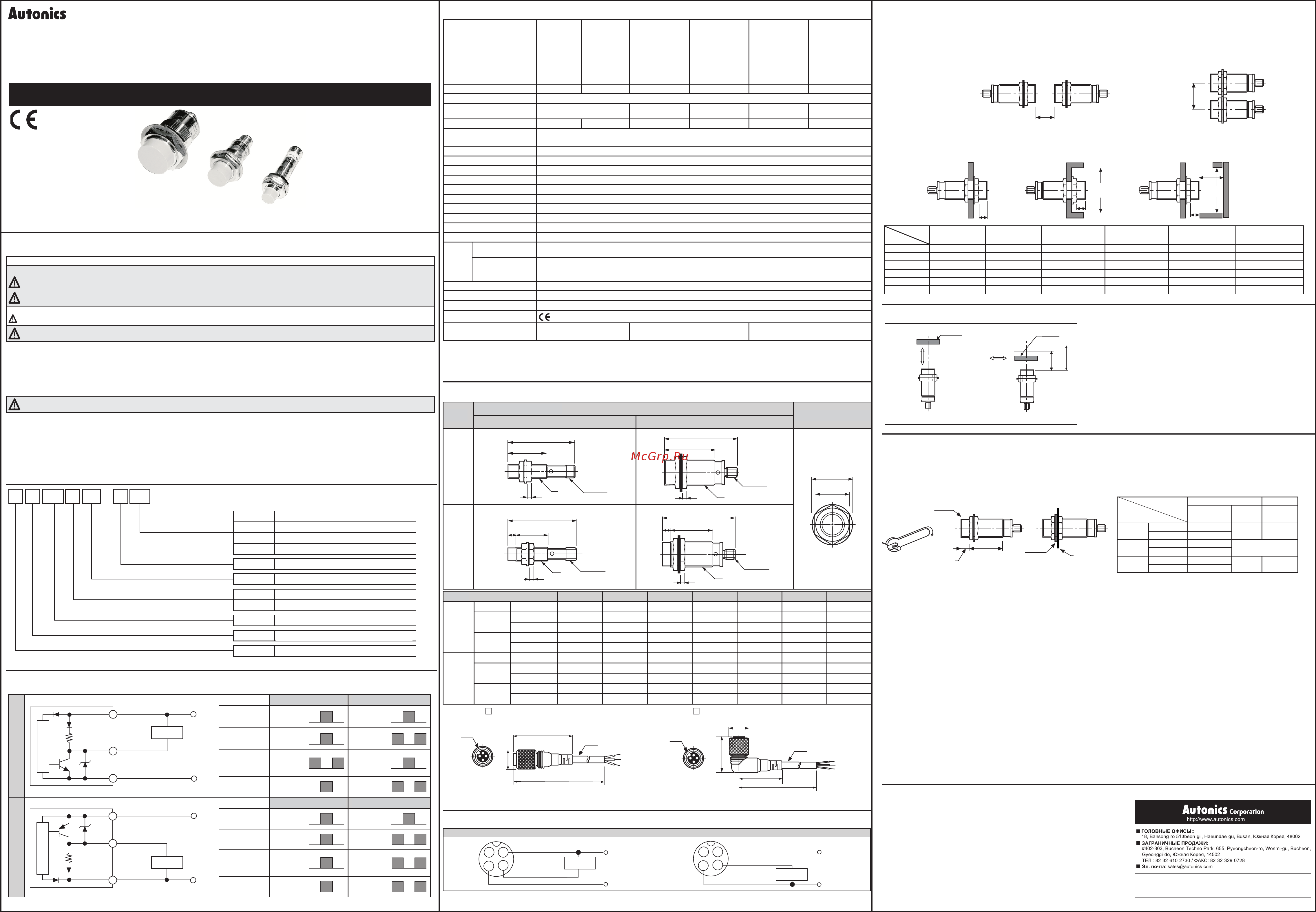
Dimensions
EP-KE-07-0180D
http://www.autonics.com
Satisable Partner For Factory Automation
■HEAD QUARTERS :
41-5. Yongdang-dong, Yangsan-si, Gyeongnam, 626-847,
Korea
■OVERSEAS SALES :
Bldg. 402 4th FL., Bucheon Techno Park, 193, Yakdae-dong,
Wonmi-gu,
Bucheon-si, Gyeonggi-do, 420-734, Korea
TEL : 82-32-610-2730 / FAX : 82-32-329-0728
■E-mail : sales@autonics.com
The proposal of a product improvement and
development :product@autonics.com
■ Proximity sensors
■ Area sensors
■ Photoelectric sensors
■ Fiber optic sensors
■ Door/Door side sensors
■ Sensor controllers
■ Graphic/Logic panels
■ Temperature controllers
■ Tachometer/Pulse(Rate) meters
■ Temperature/Humidity transducers
■ Switching power supplies
■ Stepping motors/drivers/motion controllers
■ Field network devices
■ Laser marking system(CO₂, Nd:YAG)
■ Laser welding/soldering system
■ Counters
■ Timers
■ Display units
■ Panel meters
■ Pressure sensors
■ Rotary encoders
■ Power controllers
Major products
Control output diagram & Load operating
Ordering information
NPN
+V
Brown
Black
10k
Ω
Blue
0V
Load
Main circuit
Normally Open Normally Closed
Sensing
target
Presence
Nothing
Presence
Nothing
Load
(Brown-Black)
Operation
Return
Operation
Return
Output
voltage
(Black-Blue)
H
L
H
L
Operating Indicator
(Red LED)
ON
OFF
ON
OFF
PNP
+V
Brown
Black
10k
Ω
Blue
Load
Main circuit
Normally Open Normally Closed
Sensing
target
Presence
Nothing
Presence
Nothing
Load
(Black-Blue)
Operation
Return
Operation
Return
Output
voltage
(Black-Blue)
H
L
H
L
Operating Indicator
(Red LED)
ON
OFF
ON
OFF
M A N U A L
0V
1
4
3
1
4
3
1.
In case of using this unit with machinery(Ex: nuclear power control, medical equipment, ship, vehicle,
train, airplane, combustion apparatus, safety device, crime/disaster prevention equipment, etc) which
may cause damages to human life or property, it is required to install fail-safe device.
It may cause a re, human injury or damage to property.
Caution for your safety
Warning
※
Please keep these instructions and review them before using this unit.
※
Please observe the cautions that follow;
Warning
Serious injury may result if instructions are not followed.
Caution
Product may be damaged, or injury may result if instructions are not followed.
※
The following is an explanation of the symbols used in the operation manual.
Caution:Injury or danger may occur under special conditions.
1. Do not use this unit in place where there are ammable, explosive gas, chemical or strong alkalis, acids.
It may cause a re or explosion.
2. Do not impact on this unit.
It may result in malfunction or damage to the product.
3. Do not apply AC power and observe specication rating.
It may result in serious damage to the product.
Caution
(Unit:mm)
(Unit:mm)
Note1)Allowable tightening torque of a nut may be different by the distance from the head. For allowable tightening torque and the range of front and rear
parts, refer to [Table 1] and above [Picture 1] respectively. The rear part includes a nut on the head side(see above [Picture 1]). Please apply a
tightening torque of the front part when the nut on the front is located in the front part.
Note2)The allowable tightening torque denotes a torque value when using a provided washer as above [Picture 2].
5
. Please check the voltage changes of power source in order not to excess rating power input.
6. Do not use this unit during transient time(80ms) after apply power.
7. It might result in damage to this product, if use automatic transformer. So please use insulated transformer.
8. Please make wire as short as possible in order to avoid noise.
9. Be sure to use cable as indicated specication on this product. If wrong cable or bended cable is used, it shall not maintain the water-
proof.
10. It is possible to extend cable with over 0.3mm
2
and max. 200m.
11. If the target is plated, the operating distance can be changed by the plating material.
12. It may result in malfunction by metal particle on product.
13. If there are machines(motor, welding etc), which occurs big surge around this unit, please install the varistor or absorber to source of surge, even though
there is built-in surge absorber in this unit.
14. If connecting the load with big inrush current(DC type bulb) to this unit, the big inrush current will ow since the initial resistance is low. If the current ows,
the resistance of load will be bigger, then it will return to standard current. In this case, proximity sensor might be damaged by inrush current.
If you use DC type bulb, please connect extra relay or resistance in order to protect proximity sensor from.
15. If making a transceiver close to proximity sensor or wire connection, it may cause malfunction.
1. This equipment shall not be used outdoors or beyond specied temperature range.
2. Do not apply over tensile strength of cord. (ø4: 30N max., ø5: 50N max.)
3. Do not use the same conduit with cord of this unit and electric power line or power line.
4. Do not put overload to tighten nut, please use the supplied washer for tightening.
※
It may cause malfunction if above instructions are not followed.
Mutual-interference
When several proximity sensors are mounted closely, malfunction of sensor may be caused due to mutual interference. Therefore, be
sure to provide a minimum distance between the two sensors with referring to the chart below.
Influence by surrounding metals
When sensors are mounted on metallic panel, it is required to protect the sensors from being affected by any metallic object except target.
Therefore, be sure to provide a minimum distance as below chart.
●
Sensing distance can be changed by the shape, size or material of the target.
Therefore please check the sensing distance like (a), then pass the target within
range of setting distance(Sa).
●
Setting distance(Sa)
= Sensing distance(Sn) × 70%
Ex)PRCM30-10DN
Setting distance(Sa) = 10mm × 0.7 = 7mm
※
The above specifications are subject to change without notice.
Face to Face Parallel
※
1: The response frequency is the average value. The standard sensing target is used and the width is set as 2 times of the standard sensing
target, 1/2 of the sensing distance for the distance.
※
2: The weight with packaging and the weight in parentheses is only unit weight.
※
Environment resistance is rated at no freezing or condensation.
Type
Connector type
Nut & Washer
M12 M18, M30
Flush
B
C
A
M12X1
D
B
C
A
M12X1
D
H
G
Non-
ush
B
CE
A
M12X1
D
B
CE
A
M12X1
D
Type A B C D E G H
Flush
M12 PRCM M12×1 55.8 31.5 4
-
17 21
M18
PRCM M18×1 54.3 29.5 4
-
24 29
PRCML M18×1 87.3 62.5 4
-
24 29
M30
PRCM M30×1.5 63.8 38 5
-
35 42
PRCML M30×1.5 85.8 60 5
-
35 42
Non-
ush
M12 PRCM M12×1 55.8 24.5 4 7 17 21
M18
PRCM M18×1 53.8 19 4 10 24 29
PRCML M18×1 86.8 52 4 10 24 29
M30
PRCM M30×1.5 63.8 28 5 10 35 42
PRCML M30×1.5 85.8 50 5 10 35 42
B
A
ℓ
ℓ
ℓ
n
m
ød
(a)
(b)
Target
Moving
direction
Moving
direction
Sn
Sn:
Sensing distance
Sa:
Setting distance
(70% of Sn)
{
Sa
Target
[Table 1]
Strength
Model
Front Rear
Size Torque Torque
PRCM12
Series
Flush 13mm
65kgf
.
cm
(6.37N
.
m )
120kgf
.
cm
(11.76N
.
m )
Non-ush 7mm
PRCM18
Series
Flush -
150kgf
.
c m
(14.7N
.
m)
Non-ush -
PRCM30
Series
Flush 26mm
500kgf
.
c m
( 4 9 N
.
m)
800kgf
.
c m
(78.4N
.
m )
Non-ush 12mm
[Picture 2]
mounting
bracket
washer
Front
Rear
[Picture 1]
Head
P R
Item
Shape
Connection
Body size
Dimension
Sensing distance
Output
5
CM
DN
NPN N.O.(Normally Open)
DN2
NPN N.C.(Normally Closed)
DP
PNP N.O.(Normally Open)
DP2
PNP N.C.(Normally Closed)
Number Standard sensing distance(Unit: mm)
Number Diameter of head(mm)
No mark Standard
L Long body
CM
Connector type
R Cylindrical type
P Inductive proximity sensor
DN18
L
Model
PRCM12-2DN
PRCM12-2DP
PRCM12-2DN2
PRCM12-2DP2
PRCM12-4DN
PRCM12-4DP
PRCM12-4DN2
PRCM12-4DP2
PRCM18-5DN
PRCM18-5DP
PRCM18-5DN2
PRCM18-5DP2
PRCML18-5DN
PRCML18-5DP
PRCML18-5DN2
PRCML18-5DP2
PRCM18-8DN
PRCM18-8DP
PRCM18-8DN2
PRCM18-8DP2
PRCML18-8DN
PRCML18-8DP
PRCML18-8DN2
PRCML18-8DP2
PRCM30-10DN
PRCM30-10DP
PRCM30-10DN2
PRCM30-10DP2
PRCML30-10DN
PRCML30-10DP
PRCML30-10DN2
PRCML30-10DP2
PRCM30-15DN
PRCM30-15DP
PRCM30-15DN2
PRCM30-15DP2
PRCML30-15DN
PRCML30-15DP
PRCML30-15DN2
PRCML30-15DP2
Sensing distance
2mm 4mm 5mm 8mm 10mm 15mm
Hysteresis
Max. 10% of sensing distance
Standard sensing target
12×12×1mm(Iron) 18×18×1mm(Iron) 25×25×1mm(Iron)
30×30×1mm
(Iron)
45×45×1mm
(Iron)
Setting distance
0 to 1.4mm 0 to 2.8mm 0 to 3.5mm 0 to 5.6mm 0 to 7mm 0 to 10.5mm
Power supply
(Operating voltage)
12-24VDC
(10-30VDC)
Current consumption
Max. 10mA
Response frequency
※1
1.5kHz 500kHz 500kHz 350kHz 400kHz 200kHz
Residual voltage
Max. 1.5V
Affection by Temp.
Within ±10
℃
max. of sensing distance at 20
℃
in temperature range of -25 to 70
℃
Control output
Max. 200mA
Insulation resistance
Min. 50M
Ω
(500VDC megger)
Dielectric strength
1,500VAC 50/60Hz for 1minute
Vibration
1mm amplitude at frequency of 10 to 55Hz in each of X, Y, Z directions for 2 hours
Shock
500
㎨
(50G) X, Y, Z directions for 3 times
Indicator Operating indicator(Red LED)
Environment
Ambient temperature
-25 to 70
℃
,
Storage
: -30 to 80
℃
Ambient humidity
35 to 95%RH,
Storage
: 35 to 95%RH
Protection circuit
surge protection circuit, Reverse polarity proteciton circuit, Overcurrent protection
Protection
IP67(IEC Standards)
Materials Case/Nut: Nikel plated Brass, Washer: Nikel plated Iron, Sensing surface: PBT
Approval
Unit weight
※2
Approx. 38g(Approx. 26g)
PRCM:Approx. 61g(Approx. 49g)
PRCML:Approx. 85g(Approx. 73g)
PRCM:Approx. 146g(Approx. 134g)
PRCML:Approx. 181g(Approx. 169g)
●
CID3-
●
CLD3-
Model
Item
PRCM12-2D□ PRCM12-4D□ PRCM(L)18-5D□ PRCM(L)18-8D□ PRCM(L)30-10D□ PRCM(L)30-15D□
A 12 24 30 48 60 90
B 24 36 36 54 60 90
ℓ 0 11 0 14 0 15
ød 12 36 18 54 30 90
m 6 12 15 24 30 45
n 18 36 27 54 45 90
Wiring diagram
NPN PNP
Load
Brown
Black
Blue
+V
2 1
4
3
Brown
Black
Blue
+V
2
1
4
3
Load
0V 0V
40
ø14.8
L
M12
(DC)
ø5
(DC)
M12
ø14.8
27.5
32
L
ø5
※
"L" Standard cable length is 2m, 5m.
INDUCTIVE PROXIMITY SENSOR
(CYLINDRICAL DC 3WIRE CONNECTOR)
PRCM SERIES
Thank you very much for selecting Autonics products.
For your safety, please read the following before using.
Specications Multi-interference & Inuence by surrounding metals
Caution for using
Setting distance
Dimensions
EP-KE-07-0180D
http://www.autonics.com
Satisable Partner For Factory Automation
■HEAD QUARTERS :
41-5. Yongdang-dong, Yangsan-si, Gyeongnam, 626-847,
Korea
■OVERSEAS SALES :
Bldg. 402 4th FL., Bucheon Techno Park, 193, Yakdae-dong,
Wonmi-gu,
Bucheon-si, Gyeonggi-do, 420-734, Korea
TEL : 82-32-610-2730 / FAX : 82-32-329-0728
■E-mail : sales@autonics.com
The proposal of a product improvement and
development :product@autonics.com
■ Proximity sensors
■ Area sensors
■ Photoelectric sensors
■ Fiber optic sensors
■ Door/Door side sensors
■ Sensor controllers
■ Graphic/Logic panels
■ Temperature controllers
■ Tachometer/Pulse(Rate) meters
■ Temperature/Humidity transducers
■ Switching power supplies
■ Stepping motors/drivers/motion controllers
■ Field network devices
■ Laser marking system(CO₂, Nd:YAG)
■ Laser welding/soldering system
■ Counters
■ Timers
■ Display units
■ Panel meters
■ Pressure sensors
■ Rotary encoders
■ Power controllers
Major products
Control output diagram & Load operating
Ordering information
NPN
+V
Brown
Black
10k
Ω
Blue
0V
Load
Main circuit
Normally Open Normally Closed
Sensing
target
Presence
Nothing
Presence
Nothing
Load
(Brown-Black)
Operation
Return
Operation
Return
Output
voltage
(Black-Blue)
H
L
H
L
Operating Indicator
(Red LED)
ON
OFF
ON
OFF
PNP
+V
Brown
Black
10k
Ω
Blue
Load
Main circuit
Normally Open Normally Closed
Sensing
target
Presence
Nothing
Presence
Nothing
Load
(Black-Blue)
Operation
Return
Operation
Return
Output
voltage
(Black-Blue)
H
L
H
L
Operating Indicator
(Red LED)
ON
OFF
ON
OFF
M A N U A L
0V
1
4
3
1
4
3
1.
In case of using this unit with machinery(Ex: nuclear power control, medical equipment, ship, vehicle,
train, airplane, combustion apparatus, safety device, crime/disaster prevention equipment, etc) which
may cause damages to human life or property, it is required to install fail-safe device.
It may cause a re, human injury or damage to property.
Caution for your safety
Warning
※
Please keep these instructions and review them before using this unit.
※
Please observe the cautions that follow;
Warning
Serious injury may result if instructions are not followed.
Caution
Product may be damaged, or injury may result if instructions are not followed.
※
The following is an explanation of the symbols used in the operation manual.
Caution:Injury or danger may occur under special conditions.
1. Do not use this unit in place where there are ammable, explosive gas, chemical or strong alkalis, acids.
It may cause a re or explosion.
2. Do not impact on this unit.
It may result in malfunction or damage to the product.
3. Do not apply AC power and observe specication rating.
It may result in serious damage to the product.
Caution
(Unit:mm)
(Unit:mm)
Note1)Allowable tightening torque of a nut may be different by the distance from the head. For allowable tightening torque and the range of front and rear
parts, refer to [Table 1] and above [Picture 1] respectively. The rear part includes a nut on the head side(see above [Picture 1]). Please apply a
tightening torque of the front part when the nut on the front is located in the front part.
Note2)The allowable tightening torque denotes a torque value when using a provided washer as above [Picture 2].
5
. Please check the voltage changes of power source in order not to excess rating power input.
6. Do not use this unit during transient time(80ms) after apply power.
7. It might result in damage to this product, if use automatic transformer. So please use insulated transformer.
8. Please make wire as short as possible in order to avoid noise.
9. Be sure to use cable as indicated specication on this product. If wrong cable or bended cable is used, it shall not maintain the water-
proof.
10. It is possible to extend cable with over 0.3mm
2
and max. 200m.
11. If the target is plated, the operating distance can be changed by the plating material.
12. It may result in malfunction by metal particle on product.
13. If there are machines(motor, welding etc), which occurs big surge around this unit, please install the varistor or absorber to source of surge, even though
there is built-in surge absorber in this unit.
14. If connecting the load with big inrush current(DC type bulb) to this unit, the big inrush current will ow since the initial resistance is low. If the current ows,
the resistance of load will be bigger, then it will return to standard current. In this case, proximity sensor might be damaged by inrush current.
If you use DC type bulb, please connect extra relay or resistance in order to protect proximity sensor from.
15. If making a transceiver close to proximity sensor or wire connection, it may cause malfunction.
1. This equipment shall not be used outdoors or beyond specied temperature range.
2. Do not apply over tensile strength of cord. (ø4: 30N max., ø5: 50N max.)
3. Do not use the same conduit with cord of this unit and electric power line or power line.
4. Do not put overload to tighten nut, please use the supplied washer for tightening.
※
It may cause malfunction if above instructions are not followed.
Mutual-interference
When several proximity sensors are mounted closely, malfunction of sensor may be caused due to mutual interference. Therefore, be
sure to provide a minimum distance between the two sensors with referring to the chart below.
Influence by surrounding metals
When sensors are mounted on metallic panel, it is required to protect the sensors from being affected by any metallic object except target.
Therefore, be sure to provide a minimum distance as below chart.
●
Sensing distance can be changed by the shape, size or material of the target.
Therefore please check the sensing distance like (a), then pass the target within
range of setting distance(Sa).
●
Setting distance(Sa)
= Sensing distance(Sn) × 70%
Ex)PRCM30-10DN
Setting distance(Sa) = 10mm × 0.7 = 7mm
※
The above specifications are subject to change without notice.
Face to Face Parallel
※
1: The response frequency is the average value. The standard sensing target is used and the width is set as 2 times of the standard sensing
target, 1/2 of the sensing distance for the distance.
※
2: The weight with packaging and the weight in parentheses is only unit weight.
※
Environment resistance is rated at no freezing or condensation.
Type
Connector type
Nut & Washer
M12 M18, M30
Flush
B
C
A
M12X1
D
B
C
A
M12X1
D
H
G
Non-
ush
B
CE
A
M12X1
D
B
CE
A
M12X1
D
Type A B C D E G H
Flush
M12 PRCM M12×1 55.8 31.5 4
-
17 21
M18
PRCM M18×1 54.3 29.5 4
-
24 29
PRCML M18×1 87.3 62.5 4
-
24 29
M30
PRCM M30×1.5 63.8 38 5
-
35 42
PRCML M30×1.5 85.8 60 5
-
35 42
Non-
ush
M12 PRCM M12×1 55.8 24.5 4 7 17 21
M18
PRCM M18×1 53.8 19 4 10 24 29
PRCML M18×1 86.8 52 4 10 24 29
M30
PRCM M30×1.5 63.8 28 5 10 35 42
PRCML M30×1.5 85.8 50 5 10 35 42
B
A
ℓ
ℓ
ℓ
n
m
ød
(a)
(b)
Target
Moving
direction
Moving
direction
Sn
Sn:
Sensing distance
Sa:
Setting distance
(70% of Sn)
{
Sa
Target
[Table 1]
Strength
Model
Front Rear
Size Torque Torque
PRCM12
Series
Flush 13mm
65kgf
.
cm
(6.37N
.
m )
120kgf
.
cm
(11.76N
.
m )
Non-ush 7mm
PRCM18
Series
Flush -
150kgf
.
c m
(14.7N
.
m)
Non-ush -
PRCM30
Series
Flush 26mm
500kgf
.
c m
( 4 9 N
.
m)
800kgf
.
c m
(78.4N
.
m )
Non-ush 12mm
[Picture 2]
mounting
bracket
washer
Front
Rear
[Picture 1]
Head
P R
Item
Shape
Connection
Body size
Dimension
Sensing distance
Output
5
CM
DN
NPN N.O.(Normally Open)
DN2
NPN N.C.(Normally Closed)
DP
PNP N.O.(Normally Open)
DP2
PNP N.C.(Normally Closed)
Number Standard sensing distance(Unit: mm)
Number Diameter of head(mm)
No mark Standard
L Long body
CM
Connector type
R Cylindrical type
P Inductive proximity sensor
DN18
L
Model
PRCM12-2DN
PRCM12-2DP
PRCM12-2DN2
PRCM12-2DP2
PRCM12-4DN
PRCM12-4DP
PRCM12-4DN2
PRCM12-4DP2
PRCM18-5DN
PRCM18-5DP
PRCM18-5DN2
PRCM18-5DP2
PRCML18-5DN
PRCML18-5DP
PRCML18-5DN2
PRCML18-5DP2
PRCM18-8DN
PRCM18-8DP
PRCM18-8DN2
PRCM18-8DP2
PRCML18-8DN
PRCML18-8DP
PRCML18-8DN2
PRCML18-8DP2
PRCM30-10DN
PRCM30-10DP
PRCM30-10DN2
PRCM30-10DP2
PRCML30-10DN
PRCML30-10DP
PRCML30-10DN2
PRCML30-10DP2
PRCM30-15DN
PRCM30-15DP
PRCM30-15DN2
PRCM30-15DP2
PRCML30-15DN
PRCML30-15DP
PRCML30-15DN2
PRCML30-15DP2
Sensing distance
2mm 4mm 5mm 8mm 10mm 15mm
Hysteresis
Max. 10% of sensing distance
Standard sensing target
12×12×1mm(Iron) 18×18×1mm(Iron) 25×25×1mm(Iron)
30×30×1mm
(Iron)
45×45×1mm
(Iron)
Setting distance
0 to 1.4mm 0 to 2.8mm 0 to 3.5mm 0 to 5.6mm 0 to 7mm 0 to 10.5mm
Power supply
(Operating voltage)
12-24VDC
(10-30VDC)
Current consumption
Max. 10mA
Response frequency
※1
1.5kHz 500kHz 500kHz 350kHz 400kHz 200kHz
Residual voltage
Max. 1.5V
Affection by Temp.
Within ±10
℃
max. of sensing distance at 20
℃
in temperature range of -25 to 70
℃
Control output
Max. 200mA
Insulation resistance
Min. 50M
Ω
(500VDC megger)
Dielectric strength
1,500VAC 50/60Hz for 1minute
Vibration
1mm amplitude at frequency of 10 to 55Hz in each of X, Y, Z directions for 2 hours
Shock
500
㎨
(50G) X, Y, Z directions for 3 times
Indicator Operating indicator(Red LED)
Environment
Ambient temperature
-25 to 70
℃
,
Storage
: -30 to 80
℃
Ambient humidity
35 to 95%RH,
Storage
: 35 to 95%RH
Protection circuit
surge protection circuit, Reverse polarity proteciton circuit, Overcurrent protection
Protection
IP67(IEC Standards)
Materials Case/Nut: Nikel plated Brass, Washer: Nikel plated Iron, Sensing surface: PBT
Approval
Unit weight
※2
Approx. 38g(Approx. 26g)
PRCM:Approx. 61g(Approx. 49g)
PRCML:Approx. 85g(Approx. 73g)
PRCM:Approx. 146g(Approx. 134g)
PRCML:Approx. 181g(Approx. 169g)
●
CID3-
●
CLD3-
Model
Item
PRCM12-2D□ PRCM12-4D□ PRCM(L)18-5D□ PRCM(L)18-8D□ PRCM(L)30-10D□ PRCM(L)30-15D□
A 12 24 30 48 60 90
B 24 36 36 54 60 90
ℓ 0 11 0 14 0 15
ød 12 36 18 54 30 90
m 6 12 15 24 30 45
n 18 36 27 54 45 90
Wiring diagram
NPN PNP
Load
Brown
Black
Blue
+V
2 1
4
3
Brown
Black
Blue
+V
2
1
4
3
Load
0V 0V
40
ø14.8
L
M12
(DC)
ø5
(DC)
M12
ø14.8
27.5
32
L
ø5
※
"L" Standard cable length is 2m, 5m.
Указания по технике безопасности
Ú Сохраните эти инструкции и изучите их перед началом эксплуатации этого устройства.
Ú Соблюдайте приведенные далее инструкции по технике безопасности;
Внимание
Несоблюдение этих инструкций может привести к серьезным травмам.
Осторожно
Несоблюдение этих инструкций может привести к повреждению изделия или травмам.
Ú Ниже приводится описание символов, используемых в данном руководстве по эксплуатации:
При особых условиях существует риск получения травмы или возникновения опасной ситуации.
Внимание
1. При использовании данного устройства в машинном оборудовании (например: атомные станции, медицинское оборудование,
морские суда, наземные транспортные средства, железнодорожный транспорт, воздушные суда, устройства внутреннего
сгорания, устройства безопасности, предохранительное/противоаварийное оборудование и т.п.), во время эксплуатации
которого могут возникать повреждения оборудования, а также угроза для жизни людей, следует устанавливать отказоустойчивое
устройство безопасности.
Это изделие может быть причиной пожара, травмирования персонала или повреждения имущества.
Внимание
1. Это устройство запрещается эксплуатировать в средах с воспламеняемыми или взрывоопасными газами, химикатами, сильными
щелочами и кислотами.
Это может привести к пожару или взрыву.
2. Не подвергайте это устройство ударным воздействиям.
Это может привести к возникновению сбоев в работе или к повреждению устройства.
3. Соблюдайте требования, касающиеся номинальных характеристик, и не подключайте устройство к сети переменного тока.
Это может привести к серьезному повреждению устройства.
Информация для оформления заказа
INDUCTIVE PROXIMITY SENSOR
(CYLINDRICAL DC 3WIRE CONNECTOR)
PRCM SERIES
Thank you very much for selecting Autonics products.
For your safety, please read the following before using.
Specications Multi-interference & Inuence by surrounding metals
Caution for using
Setting distance
Dimensions
EP-KE-07-0180D
http://www.autonics.com
Satisable Partner For Factory Automation
■HEAD QUARTERS :
41-5. Yongdang-dong, Yangsan-si, Gyeongnam, 626-847,
Korea
■OVERSEAS SALES :
Bldg. 402 4th FL., Bucheon Techno Park, 193, Yakdae-dong,
Wonmi-gu,
Bucheon-si, Gyeonggi-do, 420-734, Korea
TEL : 82-32-610-2730 / FAX : 82-32-329-0728
■E-mail : sales@autonics.com
The proposal of a product improvement and
development :product@autonics.com
■ Proximity sensors
■ Area sensors
■ Photoelectric sensors
■ Fiber optic sensors
■ Door/Door side sensors
■ Sensor controllers
■ Graphic/Logic panels
■ Temperature controllers
■ Tachometer/Pulse(Rate) meters
■ Temperature/Humidity transducers
■ Switching power supplies
■ Stepping motors/drivers/motion controllers
■ Field network devices
■ Laser marking system(CO₂, Nd:YAG)
■ Laser welding/soldering system
■ Counters
■ Timers
■ Display units
■ Panel meters
■ Pressure sensors
■ Rotary encoders
■ Power controllers
Major products
Control output diagram & Load operating
Ordering information
NPN
+V
Brown
Black
10k
Ω
Blue
0V
Load
Main circuit
Normally Open Normally Closed
Sensing
target
Presence
Nothing
Presence
Nothing
Load
(Brown-Black)
Operation
Return
Operation
Return
Output
voltage
(Black-Blue)
H
L
H
L
Operating Indicator
(Red LED)
ON
OFF
ON
OFF
PNP
+V
Brown
Black
10k
Ω
Blue
Load
Main circuit
Normally Open Normally Closed
Sensing
target
Presence
Nothing
Presence
Nothing
Load
(Black-Blue)
Operation
Return
Operation
Return
Output
voltage
(Black-Blue)
H
L
H
L
Operating Indicator
(Red LED)
ON
OFF
ON
OFF
M A N U A L
0V
1
4
3
1
4
3
1.
In case of using this unit with machinery(Ex: nuclear power control, medical equipment, ship, vehicle,
train, airplane, combustion apparatus, safety device, crime/disaster prevention equipment, etc) which
may cause damages to human life or property, it is required to install fail-safe device.
It may cause a re, human injury or damage to property.
Caution for your safety
Warning
※
Please keep these instructions and review them before using this unit.
※
Please observe the cautions that follow;
Warning
Serious injury may result if instructions are not followed.
Caution
Product may be damaged, or injury may result if instructions are not followed.
※
The following is an explanation of the symbols used in the operation manual.
Caution:Injury or danger may occur under special conditions.
1. Do not use this unit in place where there are ammable, explosive gas, chemical or strong alkalis, acids.
It may cause a re or explosion.
2. Do not impact on this unit.
It may result in malfunction or damage to the product.
3. Do not apply AC power and observe specication rating.
It may result in serious damage to the product.
Caution
(Unit:mm)
(Unit:mm)
Note1)Allowable tightening torque of a nut may be different by the distance from the head. For allowable tightening torque and the range of front and rear
parts, refer to [Table 1] and above [Picture 1] respectively. The rear part includes a nut on the head side(see above [Picture 1]). Please apply a
tightening torque of the front part when the nut on the front is located in the front part.
Note2)The allowable tightening torque denotes a torque value when using a provided washer as above [Picture 2].
5
. Please check the voltage changes of power source in order not to excess rating power input.
6. Do not use this unit during transient time(80ms) after apply power.
7. It might result in damage to this product, if use automatic transformer. So please use insulated transformer.
8. Please make wire as short as possible in order to avoid noise.
9. Be sure to use cable as indicated specication on this product. If wrong cable or bended cable is used, it shall not maintain the water-
proof.
10. It is possible to extend cable with over 0.3mm
2
and max. 200m.
11. If the target is plated, the operating distance can be changed by the plating material.
12. It may result in malfunction by metal particle on product.
13. If there are machines(motor, welding etc), which occurs big surge around this unit, please install the varistor or absorber to source of surge, even though
there is built-in surge absorber in this unit.
14. If connecting the load with big inrush current(DC type bulb) to this unit, the big inrush current will ow since the initial resistance is low. If the current ows,
the resistance of load will be bigger, then it will return to standard current. In this case, proximity sensor might be damaged by inrush current.
If you use DC type bulb, please connect extra relay or resistance in order to protect proximity sensor from.
15. If making a transceiver close to proximity sensor or wire connection, it may cause malfunction.
1. This equipment shall not be used outdoors or beyond specied temperature range.
2. Do not apply over tensile strength of cord. (ø4: 30N max., ø5: 50N max.)
3. Do not use the same conduit with cord of this unit and electric power line or power line.
4. Do not put overload to tighten nut, please use the supplied washer for tightening.
※
It may cause malfunction if above instructions are not followed.
Mutual-interference
When several proximity sensors are mounted closely, malfunction of sensor may be caused due to mutual interference. Therefore, be
sure to provide a minimum distance between the two sensors with referring to the chart below.
Influence by surrounding metals
When sensors are mounted on metallic panel, it is required to protect the sensors from being affected by any metallic object except target.
Therefore, be sure to provide a minimum distance as below chart.
●
Sensing distance can be changed by the shape, size or material of the target.
Therefore please check the sensing distance like (a), then pass the target within
range of setting distance(Sa).
●
Setting distance(Sa)
= Sensing distance(Sn) × 70%
Ex)PRCM30-10DN
Setting distance(Sa) = 10mm × 0.7 = 7mm
※
The above specifications are subject to change without notice.
Face to Face Parallel
※
1: The response frequency is the average value. The standard sensing target is used and the width is set as 2 times of the standard sensing
target, 1/2 of the sensing distance for the distance.
※
2: The weight with packaging and the weight in parentheses is only unit weight.
※
Environment resistance is rated at no freezing or condensation.
Type
Connector type
Nut & Washer
M12 M18, M30
Flush
B
C
A
M12X1
D
B
C
A
M12X1
D
H
G
Non-
ush
B
CE
A
M12X1
D
B
CE
A
M12X1
D
Type A B C D E G H
Flush
M12 PRCM M12×1 55.8 31.5 4
-
17 21
M18
PRCM M18×1 54.3 29.5 4
-
24 29
PRCML M18×1 87.3 62.5 4
-
24 29
M30
PRCM M30×1.5 63.8 38 5
-
35 42
PRCML M30×1.5 85.8 60 5
-
35 42
Non-
ush
M12 PRCM M12×1 55.8 24.5 4 7 17 21
M18
PRCM M18×1 53.8 19 4 10 24 29
PRCML M18×1 86.8 52 4 10 24 29
M30
PRCM M30×1.5 63.8 28 5 10 35 42
PRCML M30×1.5 85.8 50 5 10 35 42
B
A
ℓ
ℓ
ℓ
n
m
ød
(a)
(b)
Target
Moving
direction
Moving
direction
Sn
Sn:
Sensing distance
Sa:
Setting distance
(70% of Sn)
{
Sa
Target
[Table 1]
Strength
Model
Front Rear
Size Torque Torque
PRCM12
Series
Flush 13mm
65kgf
.
cm
(6.37N
.
m )
120kgf
.
cm
(11.76N
.
m )
Non-ush 7mm
PRCM18
Series
Flush -
150kgf
.
c m
(14.7N
.
m)
Non-ush -
PRCM30
Series
Flush 26mm
500kgf
.
c m
( 4 9 N
.
m)
800kgf
.
c m
(78.4N
.
m )
Non-ush 12mm
[Picture 2]
mounting
bracket
washer
Front
Rear
[Picture 1]
Head
P R
Item
Shape
Connection
Body size
Dimension
Sensing distance
Output
5
CM
DN
NPN N.O.(Normally Open)
DN2
NPN N.C.(Normally Closed)
DP
PNP N.O.(Normally Open)
DP2
PNP N.C.(Normally Closed)
Number Standard sensing distance(Unit: mm)
Number Diameter of head(mm)
No mark Standard
L Long body
CM
Connector type
R Cylindrical type
P Inductive proximity sensor
DN18
L
Model
PRCM12-2DN
PRCM12-2DP
PRCM12-2DN2
PRCM12-2DP2
PRCM12-4DN
PRCM12-4DP
PRCM12-4DN2
PRCM12-4DP2
PRCM18-5DN
PRCM18-5DP
PRCM18-5DN2
PRCM18-5DP2
PRCML18-5DN
PRCML18-5DP
PRCML18-5DN2
PRCML18-5DP2
PRCM18-8DN
PRCM18-8DP
PRCM18-8DN2
PRCM18-8DP2
PRCML18-8DN
PRCML18-8DP
PRCML18-8DN2
PRCML18-8DP2
PRCM30-10DN
PRCM30-10DP
PRCM30-10DN2
PRCM30-10DP2
PRCML30-10DN
PRCML30-10DP
PRCML30-10DN2
PRCML30-10DP2
PRCM30-15DN
PRCM30-15DP
PRCM30-15DN2
PRCM30-15DP2
PRCML30-15DN
PRCML30-15DP
PRCML30-15DN2
PRCML30-15DP2
Sensing distance
2mm 4mm 5mm 8mm 10mm 15mm
Hysteresis
Max. 10% of sensing distance
Standard sensing target
12×12×1mm(Iron) 18×18×1mm(Iron) 25×25×1mm(Iron)
30×30×1mm
(Iron)
45×45×1mm
(Iron)
Setting distance
0 to 1.4mm 0 to 2.8mm 0 to 3.5mm 0 to 5.6mm 0 to 7mm 0 to 10.5mm
Power supply
(Operating voltage)
12-24VDC
(10-30VDC)
Current consumption
Max. 10mA
Response frequency
※1
1.5kHz 500kHz 500kHz 350kHz 400kHz 200kHz
Residual voltage
Max. 1.5V
Affection by Temp.
Within ±10
℃
max. of sensing distance at 20
℃
in temperature range of -25 to 70
℃
Control output
Max. 200mA
Insulation resistance
Min. 50M
Ω
(500VDC megger)
Dielectric strength
1,500VAC 50/60Hz for 1minute
Vibration
1mm amplitude at frequency of 10 to 55Hz in each of X, Y, Z directions for 2 hours
Shock
500
㎨
(50G) X, Y, Z directions for 3 times
Indicator Operating indicator(Red LED)
Environment
Ambient temperature
-25 to 70
℃
,
Storage
: -30 to 80
℃
Ambient humidity
35 to 95%RH,
Storage
: 35 to 95%RH
Protection circuit
surge protection circuit, Reverse polarity proteciton circuit, Overcurrent protection
Protection
IP67(IEC Standards)
Materials Case/Nut: Nikel plated Brass, Washer: Nikel plated Iron, Sensing surface: PBT
Approval
Unit weight
※2
Approx. 38g(Approx. 26g)
PRCM:Approx. 61g(Approx. 49g)
PRCML:Approx. 85g(Approx. 73g)
PRCM:Approx. 146g(Approx. 134g)
PRCML:Approx. 181g(Approx. 169g)
●
CID3-
●
CLD3-
Model
Item
PRCM12-2D□ PRCM12-4D□ PRCM(L)18-5D□ PRCM(L)18-8D□ PRCM(L)30-10D□ PRCM(L)30-15D□
A 12 24 30 48 60 90
B 24 36 36 54 60 90
ℓ 0 11 0 14 0 15
ød 12 36 18 54 30 90
m 6 12 15 24 30 45
n 18 36 27 54 45 90
Wiring diagram
NPN PNP
Load
Brown
Black
Blue
+V
2 1
4
3
Brown
Black
Blue
+V
2
1
4
3
Load
0V 0V
40
ø14.8
L
M12
(DC)
ø5
(DC)
M12
ø14.8
27.5
32
L
ø5
※
"L" Standard cable length is 2m, 5m.
NPN Н.Р. (нормально разомкнут)
NPN Н.З.(нормально замкнут)
PNP Н.Р. (нормально разомкнут)
PNP Н.З. (нормально замкнут)
Стандартное расстояние срабатывания (ед. изм.: мм)
Диаметр головки (ед. изм.: мм)
Стандартные
Удлиненный корпус
Тип разъема
Цилиндрический тип
Индуктивный датчик приближения
Выход
Расстояние срабатывания
Размер
Размер корпуса
Соединение
Форма
Параметр
Схема выходов управления и работа под нагрузкой
INDUCTIVE PROXIMITY SENSOR
(CYLINDRICAL DC 3WIRE CONNECTOR)
PRCM SERIES
Thank you very much for selecting Autonics products.
For your safety, please read the following before using.
Specications Multi-interference & Inuence by surrounding metals
Caution for using
Setting distance
Dimensions
EP-KE-07-0180D
http://www.autonics.com
Satisable Partner For Factory Automation
■HEAD QUARTERS :
41-5. Yongdang-dong, Yangsan-si, Gyeongnam, 626-847,
Korea
■OVERSEAS SALES :
Bldg. 402 4th FL., Bucheon Techno Park, 193, Yakdae-dong,
Wonmi-gu,
Bucheon-si, Gyeonggi-do, 420-734, Korea
TEL : 82-32-610-2730 / FAX : 82-32-329-0728
■E-mail : sales@autonics.com
The proposal of a product improvement and
development :product@autonics.com
■ Proximity sensors
■ Area sensors
■ Photoelectric sensors
■ Fiber optic sensors
■ Door/Door side sensors
■ Sensor controllers
■ Graphic/Logic panels
■ Temperature controllers
■ Tachometer/Pulse(Rate) meters
■ Temperature/Humidity transducers
■ Switching power supplies
■ Stepping motors/drivers/motion controllers
■ Field network devices
■ Laser marking system(CO₂, Nd:YAG)
■ Laser welding/soldering system
■ Counters
■ Timers
■ Display units
■ Panel meters
■ Pressure sensors
■ Rotary encoders
■ Power controllers
Major products
Control output diagram & Load operating
Ordering information
NPN
+V
Brown
Black
10k
Ω
Blue
0V
Load
Main circuit
Normally Open Normally Closed
Sensing
target
Presence
Nothing
Presence
Nothing
Load
(Brown-Black)
Operation
Return
Operation
Return
Output
voltage
(Black-Blue)
H
L
H
L
Operating Indicator
(Red LED)
ON
OFF
ON
OFF
PNP
+V
Brown
Black
10k
Ω
Blue
Load
Main circuit
Normally Open Normally Closed
Sensing
target
Presence
Nothing
Presence
Nothing
Load
(Black-Blue)
Operation
Return
Operation
Return
Output
voltage
(Black-Blue)
H
L
H
L
Operating Indicator
(Red LED)
ON
OFF
ON
OFF
M A N U A L
0V
1
4
3
1
4
3
1.
In case of using this unit with machinery(Ex: nuclear power control, medical equipment, ship, vehicle,
train, airplane, combustion apparatus, safety device, crime/disaster prevention equipment, etc) which
may cause damages to human life or property, it is required to install fail-safe device.
It may cause a re, human injury or damage to property.
Caution for your safety
Warning
※
Please keep these instructions and review them before using this unit.
※
Please observe the cautions that follow;
Warning
Serious injury may result if instructions are not followed.
Caution
Product may be damaged, or injury may result if instructions are not followed.
※
The following is an explanation of the symbols used in the operation manual.
Caution:Injury or danger may occur under special conditions.
1. Do not use this unit in place where there are ammable, explosive gas, chemical or strong alkalis, acids.
It may cause a re or explosion.
2. Do not impact on this unit.
It may result in malfunction or damage to the product.
3. Do not apply AC power and observe specication rating.
It may result in serious damage to the product.
Caution
(Unit:mm)
(Unit:mm)
Note1)Allowable tightening torque of a nut may be different by the distance from the head. For allowable tightening torque and the range of front and rear
parts, refer to [Table 1] and above [Picture 1] respectively. The rear part includes a nut on the head side(see above [Picture 1]). Please apply a
tightening torque of the front part when the nut on the front is located in the front part.
Note2)The allowable tightening torque denotes a torque value when using a provided washer as above [Picture 2].
5
. Please check the voltage changes of power source in order not to excess rating power input.
6. Do not use this unit during transient time(80ms) after apply power.
7. It might result in damage to this product, if use automatic transformer. So please use insulated transformer.
8. Please make wire as short as possible in order to avoid noise.
9. Be sure to use cable as indicated specication on this product. If wrong cable or bended cable is used, it shall not maintain the water-
proof.
10. It is possible to extend cable with over 0.3mm
2
and max. 200m.
11. If the target is plated, the operating distance can be changed by the plating material.
12. It may result in malfunction by metal particle on product.
13. If there are machines(motor, welding etc), which occurs big surge around this unit, please install the varistor or absorber to source of surge, even though
there is built-in surge absorber in this unit.
14. If connecting the load with big inrush current(DC type bulb) to this unit, the big inrush current will ow since the initial resistance is low. If the current ows,
the resistance of load will be bigger, then it will return to standard current. In this case, proximity sensor might be damaged by inrush current.
If you use DC type bulb, please connect extra relay or resistance in order to protect proximity sensor from.
15. If making a transceiver close to proximity sensor or wire connection, it may cause malfunction.
1. This equipment shall not be used outdoors or beyond specied temperature range.
2. Do not apply over tensile strength of cord. (ø4: 30N max., ø5: 50N max.)
3. Do not use the same conduit with cord of this unit and electric power line or power line.
4. Do not put overload to tighten nut, please use the supplied washer for tightening.
※
It may cause malfunction if above instructions are not followed.
Mutual-interference
When several proximity sensors are mounted closely, malfunction of sensor may be caused due to mutual interference. Therefore, be
sure to provide a minimum distance between the two sensors with referring to the chart below.
Influence by surrounding metals
When sensors are mounted on metallic panel, it is required to protect the sensors from being affected by any metallic object except target.
Therefore, be sure to provide a minimum distance as below chart.
●
Sensing distance can be changed by the shape, size or material of the target.
Therefore please check the sensing distance like (a), then pass the target within
range of setting distance(Sa).
●
Setting distance(Sa)
= Sensing distance(Sn) × 70%
Ex)PRCM30-10DN
Setting distance(Sa) = 10mm × 0.7 = 7mm
※
The above specifications are subject to change without notice.
Face to Face Parallel
※
1: The response frequency is the average value. The standard sensing target is used and the width is set as 2 times of the standard sensing
target, 1/2 of the sensing distance for the distance.
※
2: The weight with packaging and the weight in parentheses is only unit weight.
※
Environment resistance is rated at no freezing or condensation.
Type
Connector type
Nut & Washer
M12 M18, M30
Flush
B
C
A
M12X1
D
B
C
A
M12X1
D
H
G
Non-
ush
B
CE
A
M12X1
D
B
CE
A
M12X1
D
Type A B C D E G H
Flush
M12 PRCM M12×1 55.8 31.5 4
-
17 21
M18
PRCM M18×1 54.3 29.5 4
-
24 29
PRCML M18×1 87.3 62.5 4
-
24 29
M30
PRCM M30×1.5 63.8 38 5
-
35 42
PRCML M30×1.5 85.8 60 5
-
35 42
Non-
ush
M12 PRCM M12×1 55.8 24.5 4 7 17 21
M18
PRCM M18×1 53.8 19 4 10 24 29
PRCML M18×1 86.8 52 4 10 24 29
M30
PRCM M30×1.5 63.8 28 5 10 35 42
PRCML M30×1.5 85.8 50 5 10 35 42
B
A
ℓ
ℓ
ℓ
n
m
ød
(a)
(b)
Target
Moving
direction
Moving
direction
Sn
Sn:
Sensing distance
Sa:
Setting distance
(70% of Sn)
{
Sa
Target
[Table 1]
Strength
Model
Front Rear
Size Torque Torque
PRCM12
Series
Flush 13mm
65kgf
.
cm
(6.37N
.
m )
120kgf
.
cm
(11.76N
.
m )
Non-ush 7mm
PRCM18
Series
Flush -
150kgf
.
c m
(14.7N
.
m)
Non-ush -
PRCM30
Series
Flush 26mm
500kgf
.
c m
( 4 9 N
.
m)
800kgf
.
c m
(78.4N
.
m )
Non-ush 12mm
[Picture 2]
mounting
bracket
washer
Front
Rear
[Picture 1]
Head
P R
Item
Shape
Connection
Body size
Dimension
Sensing distance
Output
5
CM
DN
NPN N.O.(Normally Open)
DN2
NPN N.C.(Normally Closed)
DP
PNP N.O.(Normally Open)
DP2
PNP N.C.(Normally Closed)
Number Standard sensing distance(Unit: mm)
Number Diameter of head(mm)
No mark Standard
L Long body
CM
Connector type
R Cylindrical type
P Inductive proximity sensor
DN18
L
Model
PRCM12-2DN
PRCM12-2DP
PRCM12-2DN2
PRCM12-2DP2
PRCM12-4DN
PRCM12-4DP
PRCM12-4DN2
PRCM12-4DP2
PRCM18-5DN
PRCM18-5DP
PRCM18-5DN2
PRCM18-5DP2
PRCML18-5DN
PRCML18-5DP
PRCML18-5DN2
PRCML18-5DP2
PRCM18-8DN
PRCM18-8DP
PRCM18-8DN2
PRCM18-8DP2
PRCML18-8DN
PRCML18-8DP
PRCML18-8DN2
PRCML18-8DP2
PRCM30-10DN
PRCM30-10DP
PRCM30-10DN2
PRCM30-10DP2
PRCML30-10DN
PRCML30-10DP
PRCML30-10DN2
PRCML30-10DP2
PRCM30-15DN
PRCM30-15DP
PRCM30-15DN2
PRCM30-15DP2
PRCML30-15DN
PRCML30-15DP
PRCML30-15DN2
PRCML30-15DP2
Sensing distance
2mm 4mm 5mm 8mm 10mm 15mm
Hysteresis
Max. 10% of sensing distance
Standard sensing target
12×12×1mm(Iron) 18×18×1mm(Iron) 25×25×1mm(Iron)
30×30×1mm
(Iron)
45×45×1mm
(Iron)
Setting distance
0 to 1.4mm 0 to 2.8mm 0 to 3.5mm 0 to 5.6mm 0 to 7mm 0 to 10.5mm
Power supply
(Operating voltage)
12-24VDC
(10-30VDC)
Current consumption
Max. 10mA
Response frequency
※1
1.5kHz 500kHz 500kHz 350kHz 400kHz 200kHz
Residual voltage
Max. 1.5V
Affection by Temp.
Within ±10
℃
max. of sensing distance at 20
℃
in temperature range of -25 to 70
℃
Control output
Max. 200mA
Insulation resistance
Min. 50M
Ω
(500VDC megger)
Dielectric strength
1,500VAC 50/60Hz for 1minute
Vibration
1mm amplitude at frequency of 10 to 55Hz in each of X, Y, Z directions for 2 hours
Shock
500
㎨
(50G) X, Y, Z directions for 3 times
Indicator Operating indicator(Red LED)
Environment
Ambient temperature
-25 to 70
℃
,
Storage
: -30 to 80
℃
Ambient humidity
35 to 95%RH,
Storage
: 35 to 95%RH
Protection circuit
surge protection circuit, Reverse polarity proteciton circuit, Overcurrent protection
Protection
IP67(IEC Standards)
Materials Case/Nut: Nikel plated Brass, Washer: Nikel plated Iron, Sensing surface: PBT
Approval
Unit weight
※2
Approx. 38g(Approx. 26g)
PRCM:Approx. 61g(Approx. 49g)
PRCML:Approx. 85g(Approx. 73g)
PRCM:Approx. 146g(Approx. 134g)
PRCML:Approx. 181g(Approx. 169g)
●
CID3-
●
CLD3-
Model
Item
PRCM12-2D□ PRCM12-4D□ PRCM(L)18-5D□ PRCM(L)18-8D□ PRCM(L)30-10D□ PRCM(L)30-15D□
A 12 24 30 48 60 90
B 24 36 36 54 60 90
ℓ 0 11 0 14 0 15
ød 12 36 18 54 30 90
m 6 12 15 24 30 45
n 18 36 27 54 45 90
Wiring diagram
NPN PNP
Load
Brown
Black
Blue
+V
2 1
4
3
Brown
Black
Blue
+V
2
1
4
3
Load
0V 0V
40
ø14.8
L
M12
(DC)
ø5
(DC)
M12
ø14.8
27.5
32
L
ø5
※
"L" Standard cable length is 2m, 5m.
Главная цепь
Главная цепь
Объект
обнаружения
Есть
Нет
Обнаружение
Возврат
Обнаружение
Возврат
ВКЛ.
ВЫКЛ.
ВКЛ.
ВЫКЛ.
Обнаружение
Возврат
Обнаружение
Возврат
Есть
Нет
Есть
Нет
Есть
Нет
Нагрузка
(коричнево-
черный)
Выходное
напряжение
(черно-синий)
Выходное
напряжение
(черно-синий)
Индик. сраб.
(красный
светодиод)
Индик. сраб.
(красный
светодиод)
Объект
обнаружения
Нагрузка
(черно-синий)
Коричневый
Коричневый
Синий
Черный
Черный
кОм
кОм
+В
+В
0В
0В
Синий
Нагрузка
Нагрузка
Нормально разомкнут
Нормально разомкнут
Нормально замкнут
Нормально замкнут
Ú Приведенные выше спецификации могут изменяться без предварительного уведомления.
ИНДУКТИВНЫЙ ДАТЧИК ПРИБЛИЖЕНИЯ
(ЦИЛИНДРИЧЕСКИЙ, С 3-КОНТАКТНЫМ РАЗЪЕМОМ
ДЛЯ ИСТОЧНИКА ПОСТ. ТОКА)
Серия PRCM
РУКОВОДСТВО ПОЛЬЗОВАТЕЛЯ
Благодарим за выбор продукции Autonics.
Перед началом эксплуатации устройства изучите указания по технике безопасности
Спецификации
Модель
PRCM12-2DN
PRCM12-2DP
PRCM12-2DN2
PRCM12-2DP2
PRCM12-4DN
PRCM12-4DP
PRCM12-4DN2
PRCM12-4DP2
PRCM18-5DN
PRCM18-5DP
PRCM18-5DN2
PRCM18-5DP2
PRCML18-5DN
PRCML18-5DP
PRCML18-5DN2
PRCML18-5DP2
PRCM18-8DN
PRCM18-8DP
PRCM18-8DN2
PRCM18-8DP2
PRCML18-8DN
PRCML18-8DP
PRCML18-8DN2
PRCML18-8DP2
PRCM30-10DN
PRCM30-10DP
PRCM30-10DN2
PRCM30-10DP2
PRCML30-10DN
PRCML30-10DP
PRCML30-10DN2
PRCML30-10DP2
PRCM30-15DN
PRCM30-15DP
PRCM30-15DN2
PRCM30-15DP2
PRCML30-15DN
PRCML30-15DP
PRCML30-15DN2
PRCML30-15DP2
Расстояние срабатывания 2мм 4мм 5мм 8мм 10мм 15мм
Гистерезис Макс. 10% рабочего расстояния
Стандартный объект
обнаружения
12x12x1мм (железо) 18x18x1мм (железо) 25x25x1мм (железо) 30x30x1мм (железо) 45x45x1мм (железо)
Устанавливаемое расстояние 0–1,4мм 0–2,8мм 0–3,5мм 0–5,6мм 0–7мм 0–10,5мм
Источник питания
12–24В пост. тока
(10–30В пост. тока)
(рабочее напряжение)
Потребляемый ток Макс. 10мА
Частота отклика*
1
1,5kHz 1500kHz 500кГц 350кГц 400кГц 200кГц
Остаточное напряжение Макс. 1,5В
Влияние температуры макс. ±20% рабочего расстояния при температуре 20°C в рамках диапазона температур от минус 25 до плюс 70°C
Выход управления Макс. 200мА
Сопротивление изоляции Мин. 50 МОм (при 500 В= по мегомметру)
Диэлектрическая прочность 2500В перем. тока, 50/60Гц в течение 1 минуты
Вибрационная прочность Амплитуда 1 мм при частоте 10–55 Гц по каждой из осей X, Y, Z в течение 2часов
Ударная нагрузка 500 м/с2 (50G) 3-х кратно по любому из направлений X, Y, Z
Индикация Индикатор срабатывания (красный светодиод)
Условия
окружаю-
щей среды
Температура окр.
среды
От минус 25 до плюс 70°C, температура хранения: От минус 30 до плюс 80°C
Отн. влажность
окруж. среды
35–95%, Отн. влажность в условиях хранения: 35–95%
Электрическая защита цепь защиты от перенапряжения, цепь защиты от неправильной полярности, Защита от перегрузки по току
Защита IP66 (стандарт МЭК)
Материалы Корпус/гайка: никелированная латунь, шайба: никелированная сталь. Поверхность чувствительного элемента: PBT
Сертификат
INDUCTIVE PROXIMITY SENSOR
(CYLINDRICAL DC 3WIRE CONNECTOR)
PRCM SERIES
Thank you very much for selecting Autonics products.
For your safety, please read the following before using.
Specications Multi-interference & Inuence by surrounding metals
Caution for using
Setting distance
Dimensions
EP-KE-07-0180D
http://www.autonics.com
Satisable Partner For Factory Automation
■HEAD QUARTERS :
41-5. Yongdang-dong, Yangsan-si, Gyeongnam, 626-847,
Korea
■OVERSEAS SALES :
Bldg. 402 4th FL., Bucheon Techno Park, 193, Yakdae-dong,
Wonmi-gu,
Bucheon-si, Gyeonggi-do, 420-734, Korea
TEL : 82-32-610-2730 / FAX : 82-32-329-0728
■E-mail : sales@autonics.com
The proposal of a product improvement and
development :product@autonics.com
■ Proximity sensors
■ Area sensors
■ Photoelectric sensors
■ Fiber optic sensors
■ Door/Door side sensors
■ Sensor controllers
■ Graphic/Logic panels
■ Temperature controllers
■ Tachometer/Pulse(Rate) meters
■ Temperature/Humidity transducers
■ Switching power supplies
■ Stepping motors/drivers/motion controllers
■ Field network devices
■ Laser marking system(CO₂, Nd:YAG)
■ Laser welding/soldering system
■ Counters
■ Timers
■ Display units
■ Panel meters
■ Pressure sensors
■ Rotary encoders
■ Power controllers
Major products
Control output diagram & Load operating
Ordering information
NPN
+V
Brown
Black
10k
Ω
Blue
0V
Load
Main circuit
Normally Open Normally Closed
Sensing
target
Presence
Nothing
Presence
Nothing
Load
(Brown-Black)
Operation
Return
Operation
Return
Output
voltage
(Black-Blue)
H
L
H
L
Operating Indicator
(Red LED)
ON
OFF
ON
OFF
PNP
+V
Brown
Black
10k
Ω
Blue
Load
Main circuit
Normally Open Normally Closed
Sensing
target
Presence
Nothing
Presence
Nothing
Load
(Black-Blue)
Operation
Return
Operation
Return
Output
voltage
(Black-Blue)
H
L
H
L
Operating Indicator
(Red LED)
ON
OFF
ON
OFF
M A N U A L
0V
1
4
3
1
4
3
1.
In case of using this unit with machinery(Ex: nuclear power control, medical equipment, ship, vehicle,
train, airplane, combustion apparatus, safety device, crime/disaster prevention equipment, etc) which
may cause damages to human life or property, it is required to install fail-safe device.
It may cause a re, human injury or damage to property.
Caution for your safety
Warning
※
Please keep these instructions and review them before using this unit.
※
Please observe the cautions that follow;
Warning
Serious injury may result if instructions are not followed.
Caution
Product may be damaged, or injury may result if instructions are not followed.
※
The following is an explanation of the symbols used in the operation manual.
Caution:Injury or danger may occur under special conditions.
1. Do not use this unit in place where there are ammable, explosive gas, chemical or strong alkalis, acids.
It may cause a re or explosion.
2. Do not impact on this unit.
It may result in malfunction or damage to the product.
3. Do not apply AC power and observe specication rating.
It may result in serious damage to the product.
Caution
(Unit:mm)
(Unit:mm)
Note1)Allowable tightening torque of a nut may be different by the distance from the head. For allowable tightening torque and the range of front and rear
parts, refer to [Table 1] and above [Picture 1] respectively. The rear part includes a nut on the head side(see above [Picture 1]). Please apply a
tightening torque of the front part when the nut on the front is located in the front part.
Note2)The allowable tightening torque denotes a torque value when using a provided washer as above [Picture 2].
5
. Please check the voltage changes of power source in order not to excess rating power input.
6. Do not use this unit during transient time(80ms) after apply power.
7. It might result in damage to this product, if use automatic transformer. So please use insulated transformer.
8. Please make wire as short as possible in order to avoid noise.
9. Be sure to use cable as indicated specication on this product. If wrong cable or bended cable is used, it shall not maintain the water-
proof.
10. It is possible to extend cable with over 0.3mm
2
and max. 200m.
11. If the target is plated, the operating distance can be changed by the plating material.
12. It may result in malfunction by metal particle on product.
13. If there are machines(motor, welding etc), which occurs big surge around this unit, please install the varistor or absorber to source of surge, even though
there is built-in surge absorber in this unit.
14. If connecting the load with big inrush current(DC type bulb) to this unit, the big inrush current will ow since the initial resistance is low. If the current ows,
the resistance of load will be bigger, then it will return to standard current. In this case, proximity sensor might be damaged by inrush current.
If you use DC type bulb, please connect extra relay or resistance in order to protect proximity sensor from.
15. If making a transceiver close to proximity sensor or wire connection, it may cause malfunction.
1. This equipment shall not be used outdoors or beyond specied temperature range.
2. Do not apply over tensile strength of cord. (ø4: 30N max., ø5: 50N max.)
3. Do not use the same conduit with cord of this unit and electric power line or power line.
4. Do not put overload to tighten nut, please use the supplied washer for tightening.
※
It may cause malfunction if above instructions are not followed.
Mutual-interference
When several proximity sensors are mounted closely, malfunction of sensor may be caused due to mutual interference. Therefore, be
sure to provide a minimum distance between the two sensors with referring to the chart below.
Influence by surrounding metals
When sensors are mounted on metallic panel, it is required to protect the sensors from being affected by any metallic object except target.
Therefore, be sure to provide a minimum distance as below chart.
●
Sensing distance can be changed by the shape, size or material of the target.
Therefore please check the sensing distance like (a), then pass the target within
range of setting distance(Sa).
●
Setting distance(Sa)
= Sensing distance(Sn) × 70%
Ex)PRCM30-10DN
Setting distance(Sa) = 10mm × 0.7 = 7mm
※
The above specifications are subject to change without notice.
Face to Face Parallel
※
1: The response frequency is the average value. The standard sensing target is used and the width is set as 2 times of the standard sensing
target, 1/2 of the sensing distance for the distance.
※
2: The weight with packaging and the weight in parentheses is only unit weight.
※
Environment resistance is rated at no freezing or condensation.
Type
Connector type
Nut & Washer
M12 M18, M30
Flush
B
C
A
M12X1
D
B
C
A
M12X1
D
H
G
Non-
ush
B
CE
A
M12X1
D
B
CE
A
M12X1
D
Type A B C D E G H
Flush
M12 PRCM M12×1 55.8 31.5 4
-
17 21
M18
PRCM M18×1 54.3 29.5 4
-
24 29
PRCML M18×1 87.3 62.5 4
-
24 29
M30
PRCM M30×1.5 63.8 38 5
-
35 42
PRCML M30×1.5 85.8 60 5
-
35 42
Non-
ush
M12 PRCM M12×1 55.8 24.5 4 7 17 21
M18
PRCM M18×1 53.8 19 4 10 24 29
PRCML M18×1 86.8 52 4 10 24 29
M30
PRCM M30×1.5 63.8 28 5 10 35 42
PRCML M30×1.5 85.8 50 5 10 35 42
B
A
ℓ
ℓ
ℓ
n
m
ød
(a)
(b)
Target
Moving
direction
Moving
direction
Sn
Sn:
Sensing distance
Sa:
Setting distance
(70% of Sn)
{
Sa
Target
[Table 1]
Strength
Model
Front Rear
Size Torque Torque
PRCM12
Series
Flush 13mm
65kgf
.
cm
(6.37N
.
m )
120kgf
.
cm
(11.76N
.
m )
Non-ush 7mm
PRCM18
Series
Flush -
150kgf
.
c m
(14.7N
.
m)
Non-ush -
PRCM30
Series
Flush 26mm
500kgf
.
c m
( 4 9 N
.
m)
800kgf
.
c m
(78.4N
.
m )
Non-ush 12mm
[Picture 2]
mounting
bracket
washer
Front
Rear
[Picture 1]
Head
P R
Item
Shape
Connection
Body size
Dimension
Sensing distance
Output
5
CM
DN
NPN N.O.(Normally Open)
DN2
NPN N.C.(Normally Closed)
DP
PNP N.O.(Normally Open)
DP2
PNP N.C.(Normally Closed)
Number Standard sensing distance(Unit: mm)
Number Diameter of head(mm)
No mark Standard
L Long body
CM
Connector type
R Cylindrical type
P Inductive proximity sensor
DN18
L
Model
PRCM12-2DN
PRCM12-2DP
PRCM12-2DN2
PRCM12-2DP2
PRCM12-4DN
PRCM12-4DP
PRCM12-4DN2
PRCM12-4DP2
PRCM18-5DN
PRCM18-5DP
PRCM18-5DN2
PRCM18-5DP2
PRCML18-5DN
PRCML18-5DP
PRCML18-5DN2
PRCML18-5DP2
PRCM18-8DN
PRCM18-8DP
PRCM18-8DN2
PRCM18-8DP2
PRCML18-8DN
PRCML18-8DP
PRCML18-8DN2
PRCML18-8DP2
PRCM30-10DN
PRCM30-10DP
PRCM30-10DN2
PRCM30-10DP2
PRCML30-10DN
PRCML30-10DP
PRCML30-10DN2
PRCML30-10DP2
PRCM30-15DN
PRCM30-15DP
PRCM30-15DN2
PRCM30-15DP2
PRCML30-15DN
PRCML30-15DP
PRCML30-15DN2
PRCML30-15DP2
Sensing distance
2mm 4mm 5mm 8mm 10mm 15mm
Hysteresis
Max. 10% of sensing distance
Standard sensing target
12×12×1mm(Iron) 18×18×1mm(Iron) 25×25×1mm(Iron)
30×30×1mm
(Iron)
45×45×1mm
(Iron)
Setting distance
0 to 1.4mm 0 to 2.8mm 0 to 3.5mm 0 to 5.6mm 0 to 7mm 0 to 10.5mm
Power supply
(Operating voltage)
12-24VDC
(10-30VDC)
Current consumption
Max. 10mA
Response frequency
※1
1.5kHz 500kHz 500kHz 350kHz 400kHz 200kHz
Residual voltage
Max. 1.5V
Affection by Temp.
Within ±10
℃
max. of sensing distance at 20
℃
in temperature range of -25 to 70
℃
Control output
Max. 200mA
Insulation resistance
Min. 50M
Ω
(500VDC megger)
Dielectric strength
1,500VAC 50/60Hz for 1minute
Vibration
1mm amplitude at frequency of 10 to 55Hz in each of X, Y, Z directions for 2 hours
Shock
500
㎨
(50G) X, Y, Z directions for 3 times
Indicator Operating indicator(Red LED)
Environment
Ambient temperature
-25 to 70
℃
,
Storage
: -30 to 80
℃
Ambient humidity
35 to 95%RH,
Storage
: 35 to 95%RH
Protection circuit
surge protection circuit, Reverse polarity proteciton circuit, Overcurrent protection
Protection
IP67(IEC Standards)
Materials Case/Nut: Nikel plated Brass, Washer: Nikel plated Iron, Sensing surface: PBT
Approval
Unit weight
※2
Approx. 38g(Approx. 26g)
PRCM:Approx. 61g(Approx. 49g)
PRCML:Approx. 85g(Approx. 73g)
PRCM:Approx. 146g(Approx. 134g)
PRCML:Approx. 181g(Approx. 169g)
●
CID3-
●
CLD3-
Model
Item
PRCM12-2D□ PRCM12-4D□ PRCM(L)18-5D□ PRCM(L)18-8D□ PRCM(L)30-10D□ PRCM(L)30-15D□
A 12 24 30 48 60 90
B 24 36 36 54 60 90
ℓ 0 11 0 14 0 15
ød 12 36 18 54 30 90
m 6 12 15 24 30 45
n 18 36 27 54 45 90
Wiring diagram
NPN PNP
Load
Brown
Black
Blue
+V
2 1
4
3
Brown
Black
Blue
+V
2
1
4
3
Load
0V 0V
40
ø14.8
L
M12
(DC)
ø5
(DC)
M12
ø14.8
27.5
32
L
ø5
※
"L" Standard cable length is 2m, 5m.
Вес*
2
Прибл. 38г (прибл. 26г)
Серия PRCM: прибл. 61г (прибл. 49г)
Серия PRCML: прибл. 85г (прибл. 73г)
Серия PRCM: прибл. 146г (прибл. 134г)
Серия PRCML: прибл. 181г (прибл. 169г)
Ú 1: Указана средняя частота отклика. При измерении используется стандартный объект обнаружения, устанавливаемая ширина равна
удвоенной ширине стандартного объекта обнаружения на расстоянии 1/2 расстояния срабатывания.
Ú 2: Значение веса устройства с упаковкой и значение веса самого устройства (в скобках).
¡ ¢
£
¤
¤
¥
¢¦ ¦
§¨©§
ª
«
¤
¤
¤
¬ ¬
®® ®® «
¯
¯
¯
¯
¯
¯
¥
¯
¯ ¯
¯
¯¯
¡ ¢¡ ¢£¡¤¡¢ ¡¥¦§ £
°
¯
¨
©
ª
«
¬
®
¯
¬¬
¤¥¦
§¡¥
¥££¡¦°¥
¤ ¤¨ ©ª«¥¦£¥ ¡¡¢ ¡¨ ©ª«¥¦£¥ ¥¢ ¬® £¡¨ ¯°±
¨
± §®§ £ª«®® §® £¡ ¦¥± ¤§®
¨
¨
¨
² ²
²
¯
¯
² ±
¯ ¯
±
Климатические характеристики указываются
для условий без замерзания или конденсации.
Размеры
INDUCTIVE PROXIMITY SENSOR
(CYLINDRICAL DC 3WIRE CONNECTOR)
PRCM SERIES
Thank you very much for selecting Autonics products.
For your safety, please read the following before using.
Specications Multi-interference & Inuence by surrounding metals
Caution for using
Setting distance
Dimensions
EP-KE-07-0180D
http://www.autonics.com
Satisable Partner For Factory Automation
■HEAD QUARTERS :
41-5. Yongdang-dong, Yangsan-si, Gyeongnam, 626-847,
Korea
■OVERSEAS SALES :
Bldg. 402 4th FL., Bucheon Techno Park, 193, Yakdae-dong,
Wonmi-gu,
Bucheon-si, Gyeonggi-do, 420-734, Korea
TEL : 82-32-610-2730 / FAX : 82-32-329-0728
■E-mail : sales@autonics.com
The proposal of a product improvement and
development :product@autonics.com
■ Proximity sensors
■ Area sensors
■ Photoelectric sensors
■ Fiber optic sensors
■ Door/Door side sensors
■ Sensor controllers
■ Graphic/Logic panels
■ Temperature controllers
■ Tachometer/Pulse(Rate) meters
■ Temperature/Humidity transducers
■ Switching power supplies
■ Stepping motors/drivers/motion controllers
■ Field network devices
■ Laser marking system(CO₂, Nd:YAG)
■ Laser welding/soldering system
■ Counters
■ Timers
■ Display units
■ Panel meters
■ Pressure sensors
■ Rotary encoders
■ Power controllers
Major products
Control output diagram & Load operating
Ordering information
NPN
+V
Brown
Black
10k
Ω
Blue
0V
Load
Main circuit
Normally Open Normally Closed
Sensing
target
Presence
Nothing
Presence
Nothing
Load
(Brown-Black)
Operation
Return
Operation
Return
Output
voltage
(Black-Blue)
H
L
H
L
Operating Indicator
(Red LED)
ON
OFF
ON
OFF
PNP
+V
Brown
Black
10k
Ω
Blue
Load
Main circuit
Normally Open Normally Closed
Sensing
target
Presence
Nothing
Presence
Nothing
Load
(Black-Blue)
Operation
Return
Operation
Return
Output
voltage
(Black-Blue)
H
L
H
L
Operating Indicator
(Red LED)
ON
OFF
ON
OFF
M A N U A L
0V
1
4
3
1
4
3
1.
In case of using this unit with machinery(Ex: nuclear power control, medical equipment, ship, vehicle,
train, airplane, combustion apparatus, safety device, crime/disaster prevention equipment, etc) which
may cause damages to human life or property, it is required to install fail-safe device.
It may cause a re, human injury or damage to property.
Caution for your safety
Warning
※
Please keep these instructions and review them before using this unit.
※
Please observe the cautions that follow;
Warning
Serious injury may result if instructions are not followed.
Caution
Product may be damaged, or injury may result if instructions are not followed.
※
The following is an explanation of the symbols used in the operation manual.
Caution:Injury or danger may occur under special conditions.
1. Do not use this unit in place where there are ammable, explosive gas, chemical or strong alkalis, acids.
It may cause a re or explosion.
2. Do not impact on this unit.
It may result in malfunction or damage to the product.
3. Do not apply AC power and observe specication rating.
It may result in serious damage to the product.
Caution
(Unit:mm)
(Unit:mm)
Note1)Allowable tightening torque of a nut may be different by the distance from the head. For allowable tightening torque and the range of front and rear
parts, refer to [Table 1] and above [Picture 1] respectively. The rear part includes a nut on the head side(see above [Picture 1]). Please apply a
tightening torque of the front part when the nut on the front is located in the front part.
Note2)The allowable tightening torque denotes a torque value when using a provided washer as above [Picture 2].
5
. Please check the voltage changes of power source in order not to excess rating power input.
6. Do not use this unit during transient time(80ms) after apply power.
7. It might result in damage to this product, if use automatic transformer. So please use insulated transformer.
8. Please make wire as short as possible in order to avoid noise.
9. Be sure to use cable as indicated specication on this product. If wrong cable or bended cable is used, it shall not maintain the water-
proof.
10. It is possible to extend cable with over 0.3mm
2
and max. 200m.
11. If the target is plated, the operating distance can be changed by the plating material.
12. It may result in malfunction by metal particle on product.
13. If there are machines(motor, welding etc), which occurs big surge around this unit, please install the varistor or absorber to source of surge, even though
there is built-in surge absorber in this unit.
14. If connecting the load with big inrush current(DC type bulb) to this unit, the big inrush current will ow since the initial resistance is low. If the current ows,
the resistance of load will be bigger, then it will return to standard current. In this case, proximity sensor might be damaged by inrush current.
If you use DC type bulb, please connect extra relay or resistance in order to protect proximity sensor from.
15. If making a transceiver close to proximity sensor or wire connection, it may cause malfunction.
1. This equipment shall not be used outdoors or beyond specied temperature range.
2. Do not apply over tensile strength of cord. (ø4: 30N max., ø5: 50N max.)
3. Do not use the same conduit with cord of this unit and electric power line or power line.
4. Do not put overload to tighten nut, please use the supplied washer for tightening.
※
It may cause malfunction if above instructions are not followed.
Mutual-interference
When several proximity sensors are mounted closely, malfunction of sensor may be caused due to mutual interference. Therefore, be
sure to provide a minimum distance between the two sensors with referring to the chart below.
Influence by surrounding metals
When sensors are mounted on metallic panel, it is required to protect the sensors from being affected by any metallic object except target.
Therefore, be sure to provide a minimum distance as below chart.
●
Sensing distance can be changed by the shape, size or material of the target.
Therefore please check the sensing distance like (a), then pass the target within
range of setting distance(Sa).
●
Setting distance(Sa)
= Sensing distance(Sn) × 70%
Ex)PRCM30-10DN
Setting distance(Sa) = 10mm × 0.7 = 7mm
※
The above specifications are subject to change without notice.
Face to Face Parallel
※
1: The response frequency is the average value. The standard sensing target is used and the width is set as 2 times of the standard sensing
target, 1/2 of the sensing distance for the distance.
※
2: The weight with packaging and the weight in parentheses is only unit weight.
※
Environment resistance is rated at no freezing or condensation.
Type
Connector type
Nut & Washer
M12 M18, M30
Flush
B
C
A
M12X1
D
B
C
A
M12X1
D
H
G
Non-
ush
B
CE
A
M12X1
D
B
CE
A
M12X1
D
Type A B C D E G H
Flush
M12 PRCM M12×1 55.8 31.5 4
-
17 21
M18
PRCM M18×1 54.3 29.5 4
-
24 29
PRCML M18×1 87.3 62.5 4
-
24 29
M30
PRCM M30×1.5 63.8 38 5
-
35 42
PRCML M30×1.5 85.8 60 5
-
35 42
Non-
ush
M12 PRCM M12×1 55.8 24.5 4 7 17 21
M18
PRCM M18×1 53.8 19 4 10 24 29
PRCML M18×1 86.8 52 4 10 24 29
M30
PRCM M30×1.5 63.8 28 5 10 35 42
PRCML M30×1.5 85.8 50 5 10 35 42
B
A
ℓ
ℓ
ℓ
n
m
ød
(a)
(b)
Target
Moving
direction
Moving
direction
Sn
Sn:
Sensing distance
Sa:
Setting distance
(70% of Sn)
{
Sa
Target
[Table 1]
Strength
Model
Front Rear
Size Torque Torque
PRCM12
Series
Flush 13mm
65kgf
.
cm
(6.37N
.
m )
120kgf
.
cm
(11.76N
.
m )
Non-ush 7mm
PRCM18
Series
Flush -
150kgf
.
c m
(14.7N
.
m)
Non-ush -
PRCM30
Series
Flush 26mm
500kgf
.
c m
( 4 9 N
.
m)
800kgf
.
c m
(78.4N
.
m )
Non-ush 12mm
[Picture 2]
mounting
bracket
washer
Front
Rear
[Picture 1]
Head
P R
Item
Shape
Connection
Body size
Dimension
Sensing distance
Output
5
CM
DN
NPN N.O.(Normally Open)
DN2
NPN N.C.(Normally Closed)
DP
PNP N.O.(Normally Open)
DP2
PNP N.C.(Normally Closed)
Number Standard sensing distance(Unit: mm)
Number Diameter of head(mm)
No mark Standard
L Long body
CM
Connector type
R Cylindrical type
P Inductive proximity sensor
DN18
L
Model
PRCM12-2DN
PRCM12-2DP
PRCM12-2DN2
PRCM12-2DP2
PRCM12-4DN
PRCM12-4DP
PRCM12-4DN2
PRCM12-4DP2
PRCM18-5DN
PRCM18-5DP
PRCM18-5DN2
PRCM18-5DP2
PRCML18-5DN
PRCML18-5DP
PRCML18-5DN2
PRCML18-5DP2
PRCM18-8DN
PRCM18-8DP
PRCM18-8DN2
PRCM18-8DP2
PRCML18-8DN
PRCML18-8DP
PRCML18-8DN2
PRCML18-8DP2
PRCM30-10DN
PRCM30-10DP
PRCM30-10DN2
PRCM30-10DP2
PRCML30-10DN
PRCML30-10DP
PRCML30-10DN2
PRCML30-10DP2
PRCM30-15DN
PRCM30-15DP
PRCM30-15DN2
PRCM30-15DP2
PRCML30-15DN
PRCML30-15DP
PRCML30-15DN2
PRCML30-15DP2
Sensing distance
2mm 4mm 5mm 8mm 10mm 15mm
Hysteresis
Max. 10% of sensing distance
Standard sensing target
12×12×1mm(Iron) 18×18×1mm(Iron) 25×25×1mm(Iron)
30×30×1mm
(Iron)
45×45×1mm
(Iron)
Setting distance
0 to 1.4mm 0 to 2.8mm 0 to 3.5mm 0 to 5.6mm 0 to 7mm 0 to 10.5mm
Power supply
(Operating voltage)
12-24VDC
(10-30VDC)
Current consumption
Max. 10mA
Response frequency
※1
1.5kHz 500kHz 500kHz 350kHz 400kHz 200kHz
Residual voltage
Max. 1.5V
Affection by Temp.
Within ±10
℃
max. of sensing distance at 20
℃
in temperature range of -25 to 70
℃
Control output
Max. 200mA
Insulation resistance
Min. 50M
Ω
(500VDC megger)
Dielectric strength
1,500VAC 50/60Hz for 1minute
Vibration
1mm amplitude at frequency of 10 to 55Hz in each of X, Y, Z directions for 2 hours
Shock
500
㎨
(50G) X, Y, Z directions for 3 times
Indicator Operating indicator(Red LED)
Environment
Ambient temperature
-25 to 70
℃
,
Storage
: -30 to 80
℃
Ambient humidity
35 to 95%RH,
Storage
: 35 to 95%RH
Protection circuit
surge protection circuit, Reverse polarity proteciton circuit, Overcurrent protection
Protection
IP67(IEC Standards)
Materials Case/Nut: Nikel plated Brass, Washer: Nikel plated Iron, Sensing surface: PBT
Approval
Unit weight
※2
Approx. 38g(Approx. 26g)
PRCM:Approx. 61g(Approx. 49g)
PRCML:Approx. 85g(Approx. 73g)
PRCM:Approx. 146g(Approx. 134g)
PRCML:Approx. 181g(Approx. 169g)
●
CID3-
●
CLD3-
Model
Item
PRCM12-2D□ PRCM12-4D□ PRCM(L)18-5D□ PRCM(L)18-8D□ PRCM(L)30-10D□ PRCM(L)30-15D□
A 12 24 30 48 60 90
B 24 36 36 54 60 90
ℓ 0 11 0 14 0 15
ød 12 36 18 54 30 90
m 6 12 15 24 30 45
n 18 36 27 54 45 90
Wiring diagram
NPN PNP
Load
Brown
Black
Blue
+V
2 1
4
3
Brown
Black
Blue
+V
2
1
4
3
Load
0V 0V
40
ø14.8
L
M12
(DC)
ø5
(DC)
M12
ø14.8
27.5
32
L
ø5
※
"L" Standard cable length is 2m, 5m.
Тип
Тип
Тип разъема
Гайка и шайба
Заподлицо
Заподлицо
Не
заподлицо
Не
заподлицо
Ú ”L”, стандартная длина кабеля составляет 2 м и 5 м.
Схема подключения
INDUCTIVE PROXIMITY SENSOR
(CYLINDRICAL DC 3WIRE CONNECTOR)
PRCM SERIES
Thank you very much for selecting Autonics products.
For your safety, please read the following before using.
Specications Multi-interference & Inuence by surrounding metals
Caution for using
Setting distance
Dimensions
EP-KE-07-0180D
http://www.autonics.com
Satisable Partner For Factory Automation
■HEAD QUARTERS :
41-5. Yongdang-dong, Yangsan-si, Gyeongnam, 626-847,
Korea
■OVERSEAS SALES :
Bldg. 402 4th FL., Bucheon Techno Park, 193, Yakdae-dong,
Wonmi-gu,
Bucheon-si, Gyeonggi-do, 420-734, Korea
TEL : 82-32-610-2730 / FAX : 82-32-329-0728
■E-mail : sales@autonics.com
The proposal of a product improvement and
development :product@autonics.com
■ Proximity sensors
■ Area sensors
■ Photoelectric sensors
■ Fiber optic sensors
■ Door/Door side sensors
■ Sensor controllers
■ Graphic/Logic panels
■ Temperature controllers
■ Tachometer/Pulse(Rate) meters
■ Temperature/Humidity transducers
■ Switching power supplies
■ Stepping motors/drivers/motion controllers
■ Field network devices
■ Laser marking system(CO₂, Nd:YAG)
■ Laser welding/soldering system
■ Counters
■ Timers
■ Display units
■ Panel meters
■ Pressure sensors
■ Rotary encoders
■ Power controllers
Major products
Control output diagram & Load operating
Ordering information
NPN
+V
Brown
Black
10k
Ω
Blue
0V
Load
Main circuit
Normally Open Normally Closed
Sensing
target
Presence
Nothing
Presence
Nothing
Load
(Brown-Black)
Operation
Return
Operation
Return
Output
voltage
(Black-Blue)
H
L
H
L
Operating Indicator
(Red LED)
ON
OFF
ON
OFF
PNP
+V
Brown
Black
10k
Ω
Blue
Load
Main circuit
Normally Open Normally Closed
Sensing
target
Presence
Nothing
Presence
Nothing
Load
(Black-Blue)
Operation
Return
Operation
Return
Output
voltage
(Black-Blue)
H
L
H
L
Operating Indicator
(Red LED)
ON
OFF
ON
OFF
M A N U A L
0V
1
4
3
1
4
3
1.
In case of using this unit with machinery(Ex: nuclear power control, medical equipment, ship, vehicle,
train, airplane, combustion apparatus, safety device, crime/disaster prevention equipment, etc) which
may cause damages to human life or property, it is required to install fail-safe device.
It may cause a re, human injury or damage to property.
Caution for your safety
Warning
※
Please keep these instructions and review them before using this unit.
※
Please observe the cautions that follow;
Warning
Serious injury may result if instructions are not followed.
Caution
Product may be damaged, or injury may result if instructions are not followed.
※
The following is an explanation of the symbols used in the operation manual.
Caution:Injury or danger may occur under special conditions.
1. Do not use this unit in place where there are ammable, explosive gas, chemical or strong alkalis, acids.
It may cause a re or explosion.
2. Do not impact on this unit.
It may result in malfunction or damage to the product.
3. Do not apply AC power and observe specication rating.
It may result in serious damage to the product.
Caution
(Unit:mm)
(Unit:mm)
Note1)Allowable tightening torque of a nut may be different by the distance from the head. For allowable tightening torque and the range of front and rear
parts, refer to [Table 1] and above [Picture 1] respectively. The rear part includes a nut on the head side(see above [Picture 1]). Please apply a
tightening torque of the front part when the nut on the front is located in the front part.
Note2)The allowable tightening torque denotes a torque value when using a provided washer as above [Picture 2].
5
. Please check the voltage changes of power source in order not to excess rating power input.
6. Do not use this unit during transient time(80ms) after apply power.
7. It might result in damage to this product, if use automatic transformer. So please use insulated transformer.
8. Please make wire as short as possible in order to avoid noise.
9. Be sure to use cable as indicated specication on this product. If wrong cable or bended cable is used, it shall not maintain the water-
proof.
10. It is possible to extend cable with over 0.3mm
2
and max. 200m.
11. If the target is plated, the operating distance can be changed by the plating material.
12. It may result in malfunction by metal particle on product.
13. If there are machines(motor, welding etc), which occurs big surge around this unit, please install the varistor or absorber to source of surge, even though
there is built-in surge absorber in this unit.
14. If connecting the load with big inrush current(DC type bulb) to this unit, the big inrush current will ow since the initial resistance is low. If the current ows,
the resistance of load will be bigger, then it will return to standard current. In this case, proximity sensor might be damaged by inrush current.
If you use DC type bulb, please connect extra relay or resistance in order to protect proximity sensor from.
15. If making a transceiver close to proximity sensor or wire connection, it may cause malfunction.
1. This equipment shall not be used outdoors or beyond specied temperature range.
2. Do not apply over tensile strength of cord. (ø4: 30N max., ø5: 50N max.)
3. Do not use the same conduit with cord of this unit and electric power line or power line.
4. Do not put overload to tighten nut, please use the supplied washer for tightening.
※
It may cause malfunction if above instructions are not followed.
Mutual-interference
When several proximity sensors are mounted closely, malfunction of sensor may be caused due to mutual interference. Therefore, be
sure to provide a minimum distance between the two sensors with referring to the chart below.
Influence by surrounding metals
When sensors are mounted on metallic panel, it is required to protect the sensors from being affected by any metallic object except target.
Therefore, be sure to provide a minimum distance as below chart.
●
Sensing distance can be changed by the shape, size or material of the target.
Therefore please check the sensing distance like (a), then pass the target within
range of setting distance(Sa).
●
Setting distance(Sa)
= Sensing distance(Sn) × 70%
Ex)PRCM30-10DN
Setting distance(Sa) = 10mm × 0.7 = 7mm
※
The above specifications are subject to change without notice.
Face to Face Parallel
※
1: The response frequency is the average value. The standard sensing target is used and the width is set as 2 times of the standard sensing
target, 1/2 of the sensing distance for the distance.
※
2: The weight with packaging and the weight in parentheses is only unit weight.
※
Environment resistance is rated at no freezing or condensation.
Type
Connector type
Nut & Washer
M12 M18, M30
Flush
B
C
A
M12X1
D
B
C
A
M12X1
D
H
G
Non-
ush
B
CE
A
M12X1
D
B
CE
A
M12X1
D
Type A B C D E G H
Flush
M12 PRCM M12×1 55.8 31.5 4
-
17 21
M18
PRCM M18×1 54.3 29.5 4
-
24 29
PRCML M18×1 87.3 62.5 4
-
24 29
M30
PRCM M30×1.5 63.8 38 5
-
35 42
PRCML M30×1.5 85.8 60 5
-
35 42
Non-
ush
M12 PRCM M12×1 55.8 24.5 4 7 17 21
M18
PRCM M18×1 53.8 19 4 10 24 29
PRCML M18×1 86.8 52 4 10 24 29
M30
PRCM M30×1.5 63.8 28 5 10 35 42
PRCML M30×1.5 85.8 50 5 10 35 42
B
A
ℓ
ℓ
ℓ
n
m
ød
(a)
(b)
Target
Moving
direction
Moving
direction
Sn
Sn:
Sensing distance
Sa:
Setting distance
(70% of Sn)
{
Sa
Target
[Table 1]
Strength
Model
Front Rear
Size Torque Torque
PRCM12
Series
Flush 13mm
65kgf
.
cm
(6.37N
.
m )
120kgf
.
cm
(11.76N
.
m )
Non-ush 7mm
PRCM18
Series
Flush -
150kgf
.
c m
(14.7N
.
m)
Non-ush -
PRCM30
Series
Flush 26mm
500kgf
.
c m
( 4 9 N
.
m)
800kgf
.
c m
(78.4N
.
m )
Non-ush 12mm
[Picture 2]
mounting
bracket
washer
Front
Rear
[Picture 1]
Head
P R
Item
Shape
Connection
Body size
Dimension
Sensing distance
Output
5
CM
DN
NPN N.O.(Normally Open)
DN2
NPN N.C.(Normally Closed)
DP
PNP N.O.(Normally Open)
DP2
PNP N.C.(Normally Closed)
Number Standard sensing distance(Unit: mm)
Number Diameter of head(mm)
No mark Standard
L Long body
CM
Connector type
R Cylindrical type
P Inductive proximity sensor
DN18
L
Model
PRCM12-2DN
PRCM12-2DP
PRCM12-2DN2
PRCM12-2DP2
PRCM12-4DN
PRCM12-4DP
PRCM12-4DN2
PRCM12-4DP2
PRCM18-5DN
PRCM18-5DP
PRCM18-5DN2
PRCM18-5DP2
PRCML18-5DN
PRCML18-5DP
PRCML18-5DN2
PRCML18-5DP2
PRCM18-8DN
PRCM18-8DP
PRCM18-8DN2
PRCM18-8DP2
PRCML18-8DN
PRCML18-8DP
PRCML18-8DN2
PRCML18-8DP2
PRCM30-10DN
PRCM30-10DP
PRCM30-10DN2
PRCM30-10DP2
PRCML30-10DN
PRCML30-10DP
PRCML30-10DN2
PRCML30-10DP2
PRCM30-15DN
PRCM30-15DP
PRCM30-15DN2
PRCM30-15DP2
PRCML30-15DN
PRCML30-15DP
PRCML30-15DN2
PRCML30-15DP2
Sensing distance
2mm 4mm 5mm 8mm 10mm 15mm
Hysteresis
Max. 10% of sensing distance
Standard sensing target
12×12×1mm(Iron) 18×18×1mm(Iron) 25×25×1mm(Iron)
30×30×1mm
(Iron)
45×45×1mm
(Iron)
Setting distance
0 to 1.4mm 0 to 2.8mm 0 to 3.5mm 0 to 5.6mm 0 to 7mm 0 to 10.5mm
Power supply
(Operating voltage)
12-24VDC
(10-30VDC)
Current consumption
Max. 10mA
Response frequency
※1
1.5kHz 500kHz 500kHz 350kHz 400kHz 200kHz
Residual voltage
Max. 1.5V
Affection by Temp.
Within ±10
℃
max. of sensing distance at 20
℃
in temperature range of -25 to 70
℃
Control output
Max. 200mA
Insulation resistance
Min. 50M
Ω
(500VDC megger)
Dielectric strength
1,500VAC 50/60Hz for 1minute
Vibration
1mm amplitude at frequency of 10 to 55Hz in each of X, Y, Z directions for 2 hours
Shock
500
㎨
(50G) X, Y, Z directions for 3 times
Indicator Operating indicator(Red LED)
Environment
Ambient temperature
-25 to 70
℃
,
Storage
: -30 to 80
℃
Ambient humidity
35 to 95%RH,
Storage
: 35 to 95%RH
Protection circuit
surge protection circuit, Reverse polarity proteciton circuit, Overcurrent protection
Protection
IP67(IEC Standards)
Materials Case/Nut: Nikel plated Brass, Washer: Nikel plated Iron, Sensing surface: PBT
Approval
Unit weight
※2
Approx. 38g(Approx. 26g)
PRCM:Approx. 61g(Approx. 49g)
PRCML:Approx. 85g(Approx. 73g)
PRCM:Approx. 146g(Approx. 134g)
PRCML:Approx. 181g(Approx. 169g)
●
CID3-
●
CLD3-
Model
Item
PRCM12-2D□ PRCM12-4D□ PRCM(L)18-5D□ PRCM(L)18-8D□ PRCM(L)30-10D□ PRCM(L)30-15D□
A 12 24 30 48 60 90
B 24 36 36 54 60 90
ℓ 0 11 0 14 0 15
ød 12 36 18 54 30 90
m 6 12 15 24 30 45
n 18 36 27 54 45 90
Wiring diagram
NPN PNP
Load
Brown
Black
Blue
+V
2 1
4
3
Brown
Black
Blue
+V
2
1
4
3
Load
0V 0V
40
ø14.8
L
M12
(DC)
ø5
(DC)
M12
ø14.8
27.5
32
L
ø5
※
"L" Standard cable length is 2m, 5m.
Коричневый
+В +В
0В 0В
Черный
Синий
Синий
Черный
Коричневый
Нагрузка
Нагрузка
(Единицы измерения: мм)
Взаимные помехи и воздействие находящихся рядом металлических
объектов
• Взаимные помехи
При установке нескольких датчиков приближения близко друг к другу сбои в работе датчика могут быть обусловлены взаимными помехами.
Поэтому обеспечьте необходимое минимальное расстояние между соседними датчиками, в соответствии с данными, приведенными в
нижеприведенных таблицах.
¡ ¢
£
¤
¤
¥
¢¦ ¦
§¨©§
ª
«
¤
¤
¤
¬ ¬
®® ®® «
¯
¯
¯
¯
¯
¯
¥
¯
¯ ¯
¯
¯¯
¡ ¢¡ ¢£¡¤¡¢ ¡¥¦§ £
°
¯
¨
©
ª
«
¬
®
¯
¬¬
¤¥¦
§¡¥
¥££¡¦°¥
¤ ¤¨ ©ª«¥¦£¥ ¡¡¢ ¡¨ ©ª«¥¦£¥ ¥¢ ¬® £¡¨ ¯°±
¨
± §®§ £ª«®® §® £¡ ¦¥± ¤§®
¨
¨
¨
² ²
²
¯
¯
² ±
¯ ¯
±
¡ ¢
£
¤
¤
¥
¢¦ ¦
§¨©§
ª
«
¤
¤
¤
¬ ¬
®® ®® «
¯
¯
¯
¯
¯
¯
¥
¯
¯ ¯
¯
¯¯
¡ ¢¡ ¢£¡¤¡¢ ¡¥¦§ £
°
¯
¨
©
ª
«
¬
®
¯
¬¬
¤¥¦
§¡¥
¥££¡¦°¥
¤ ¤¨ ©ª«¥¦£¥ ¡¡¢ ¡¨ ©ª«¥¦£¥ ¥¢ ¬® £¡¨ ¯°±
¨
± §®§ £ª«®® §® £¡ ¦¥± ¤§®
¨
¨
¨
² ²
²
¯
¯
² ±
¯ ¯
±
Встречное расположение Параллельное
расположение
• Воздействие находящихся рядом металлических объектов
Если датчики монтируются на металлической панели, необходимо защитить датчики от сбоев в работе, вызываемых находящимися рядом
металлическими объектами, за исключением объекта. Поэтому обеспечьте необходимое минимальное расстояние, в соответствии с
данными, приведенными в нижеприведенной таблице.
INDUCTIVE PROXIMITY SENSOR
(CYLINDRICAL DC 3WIRE CONNECTOR)
PRCM SERIES
Thank you very much for selecting Autonics products.
For your safety, please read the following before using.
Specications Multi-interference & Inuence by surrounding metals
Caution for using
Setting distance
Dimensions
EP-KE-07-0180D
http://www.autonics.com
Satisable Partner For Factory Automation
■HEAD QUARTERS :
41-5. Yongdang-dong, Yangsan-si, Gyeongnam, 626-847,
Korea
■OVERSEAS SALES :
Bldg. 402 4th FL., Bucheon Techno Park, 193, Yakdae-dong,
Wonmi-gu,
Bucheon-si, Gyeonggi-do, 420-734, Korea
TEL : 82-32-610-2730 / FAX : 82-32-329-0728
■E-mail : sales@autonics.com
The proposal of a product improvement and
development :product@autonics.com
■ Proximity sensors
■ Area sensors
■ Photoelectric sensors
■ Fiber optic sensors
■ Door/Door side sensors
■ Sensor controllers
■ Graphic/Logic panels
■ Temperature controllers
■ Tachometer/Pulse(Rate) meters
■ Temperature/Humidity transducers
■ Switching power supplies
■ Stepping motors/drivers/motion controllers
■ Field network devices
■ Laser marking system(CO₂, Nd:YAG)
■ Laser welding/soldering system
■ Counters
■ Timers
■ Display units
■ Panel meters
■ Pressure sensors
■ Rotary encoders
■ Power controllers
Major products
Control output diagram & Load operating
Ordering information
NPN
+V
Brown
Black
10k
Ω
Blue
0V
Load
Main circuit
Normally Open Normally Closed
Sensing
target
Presence
Nothing
Presence
Nothing
Load
(Brown-Black)
Operation
Return
Operation
Return
Output
voltage
(Black-Blue)
H
L
H
L
Operating Indicator
(Red LED)
ON
OFF
ON
OFF
PNP
+V
Brown
Black
10k
Ω
Blue
Load
Main circuit
Normally Open Normally Closed
Sensing
target
Presence
Nothing
Presence
Nothing
Load
(Black-Blue)
Operation
Return
Operation
Return
Output
voltage
(Black-Blue)
H
L
H
L
Operating Indicator
(Red LED)
ON
OFF
ON
OFF
M A N U A L
0V
1
4
3
1
4
3
1.
In case of using this unit with machinery(Ex: nuclear power control, medical equipment, ship, vehicle,
train, airplane, combustion apparatus, safety device, crime/disaster prevention equipment, etc) which
may cause damages to human life or property, it is required to install fail-safe device.
It may cause a re, human injury or damage to property.
Caution for your safety
Warning
※
Please keep these instructions and review them before using this unit.
※
Please observe the cautions that follow;
Warning
Serious injury may result if instructions are not followed.
Caution
Product may be damaged, or injury may result if instructions are not followed.
※
The following is an explanation of the symbols used in the operation manual.
Caution:Injury or danger may occur under special conditions.
1. Do not use this unit in place where there are ammable, explosive gas, chemical or strong alkalis, acids.
It may cause a re or explosion.
2. Do not impact on this unit.
It may result in malfunction or damage to the product.
3. Do not apply AC power and observe specication rating.
It may result in serious damage to the product.
Caution
(Unit:mm)
(Unit:mm)
Note1)Allowable tightening torque of a nut may be different by the distance from the head. For allowable tightening torque and the range of front and rear
parts, refer to [Table 1] and above [Picture 1] respectively. The rear part includes a nut on the head side(see above [Picture 1]). Please apply a
tightening torque of the front part when the nut on the front is located in the front part.
Note2)The allowable tightening torque denotes a torque value when using a provided washer as above [Picture 2].
5
. Please check the voltage changes of power source in order not to excess rating power input.
6. Do not use this unit during transient time(80ms) after apply power.
7. It might result in damage to this product, if use automatic transformer. So please use insulated transformer.
8. Please make wire as short as possible in order to avoid noise.
9. Be sure to use cable as indicated specication on this product. If wrong cable or bended cable is used, it shall not maintain the water-
proof.
10. It is possible to extend cable with over 0.3mm
2
and max. 200m.
11. If the target is plated, the operating distance can be changed by the plating material.
12. It may result in malfunction by metal particle on product.
13. If there are machines(motor, welding etc), which occurs big surge around this unit, please install the varistor or absorber to source of surge, even though
there is built-in surge absorber in this unit.
14. If connecting the load with big inrush current(DC type bulb) to this unit, the big inrush current will ow since the initial resistance is low. If the current ows,
the resistance of load will be bigger, then it will return to standard current. In this case, proximity sensor might be damaged by inrush current.
If you use DC type bulb, please connect extra relay or resistance in order to protect proximity sensor from.
15. If making a transceiver close to proximity sensor or wire connection, it may cause malfunction.
1. This equipment shall not be used outdoors or beyond specied temperature range.
2. Do not apply over tensile strength of cord. (ø4: 30N max., ø5: 50N max.)
3. Do not use the same conduit with cord of this unit and electric power line or power line.
4. Do not put overload to tighten nut, please use the supplied washer for tightening.
※
It may cause malfunction if above instructions are not followed.
Mutual-interference
When several proximity sensors are mounted closely, malfunction of sensor may be caused due to mutual interference. Therefore, be
sure to provide a minimum distance between the two sensors with referring to the chart below.
Influence by surrounding metals
When sensors are mounted on metallic panel, it is required to protect the sensors from being affected by any metallic object except target.
Therefore, be sure to provide a minimum distance as below chart.
●
Sensing distance can be changed by the shape, size or material of the target.
Therefore please check the sensing distance like (a), then pass the target within
range of setting distance(Sa).
●
Setting distance(Sa)
= Sensing distance(Sn) × 70%
Ex)PRCM30-10DN
Setting distance(Sa) = 10mm × 0.7 = 7mm
※
The above specifications are subject to change without notice.
Face to Face Parallel
※
1: The response frequency is the average value. The standard sensing target is used and the width is set as 2 times of the standard sensing
target, 1/2 of the sensing distance for the distance.
※
2: The weight with packaging and the weight in parentheses is only unit weight.
※
Environment resistance is rated at no freezing or condensation.
Type
Connector type
Nut & Washer
M12 M18, M30
Flush
B
C
A
M12X1
D
B
C
A
M12X1
D
H
G
Non-
ush
B
CE
A
M12X1
D
B
CE
A
M12X1
D
Type A B C D E G H
Flush
M12 PRCM M12×1 55.8 31.5 4
-
17 21
M18
PRCM M18×1 54.3 29.5 4
-
24 29
PRCML M18×1 87.3 62.5 4
-
24 29
M30
PRCM M30×1.5 63.8 38 5
-
35 42
PRCML M30×1.5 85.8 60 5
-
35 42
Non-
ush
M12 PRCM M12×1 55.8 24.5 4 7 17 21
M18
PRCM M18×1 53.8 19 4 10 24 29
PRCML M18×1 86.8 52 4 10 24 29
M30
PRCM M30×1.5 63.8 28 5 10 35 42
PRCML M30×1.5 85.8 50 5 10 35 42
B
A
ℓ
ℓ
ℓ
n
m
ød
(a)
(b)
Target
Moving
direction
Moving
direction
Sn
Sn:
Sensing distance
Sa:
Setting distance
(70% of Sn)
{
Sa
Target
[Table 1]
Strength
Model
Front Rear
Size Torque Torque
PRCM12
Series
Flush 13mm
65kgf
.
cm
(6.37N
.
m )
120kgf
.
cm
(11.76N
.
m )
Non-ush 7mm
PRCM18
Series
Flush -
150kgf
.
c m
(14.7N
.
m)
Non-ush -
PRCM30
Series
Flush 26mm
500kgf
.
c m
( 4 9 N
.
m)
800kgf
.
c m
(78.4N
.
m )
Non-ush 12mm
[Picture 2]
mounting
bracket
washer
Front
Rear
[Picture 1]
Head
P R
Item
Shape
Connection
Body size
Dimension
Sensing distance
Output
5
CM
DN
NPN N.O.(Normally Open)
DN2
NPN N.C.(Normally Closed)
DP
PNP N.O.(Normally Open)
DP2
PNP N.C.(Normally Closed)
Number Standard sensing distance(Unit: mm)
Number Diameter of head(mm)
No mark Standard
L Long body
CM
Connector type
R Cylindrical type
P Inductive proximity sensor
DN18
L
Model
PRCM12-2DN
PRCM12-2DP
PRCM12-2DN2
PRCM12-2DP2
PRCM12-4DN
PRCM12-4DP
PRCM12-4DN2
PRCM12-4DP2
PRCM18-5DN
PRCM18-5DP
PRCM18-5DN2
PRCM18-5DP2
PRCML18-5DN
PRCML18-5DP
PRCML18-5DN2
PRCML18-5DP2
PRCM18-8DN
PRCM18-8DP
PRCM18-8DN2
PRCM18-8DP2
PRCML18-8DN
PRCML18-8DP
PRCML18-8DN2
PRCML18-8DP2
PRCM30-10DN
PRCM30-10DP
PRCM30-10DN2
PRCM30-10DP2
PRCML30-10DN
PRCML30-10DP
PRCML30-10DN2
PRCML30-10DP2
PRCM30-15DN
PRCM30-15DP
PRCM30-15DN2
PRCM30-15DP2
PRCML30-15DN
PRCML30-15DP
PRCML30-15DN2
PRCML30-15DP2
Sensing distance
2mm 4mm 5mm 8mm 10mm 15mm
Hysteresis
Max. 10% of sensing distance
Standard sensing target
12×12×1mm(Iron) 18×18×1mm(Iron) 25×25×1mm(Iron)
30×30×1mm
(Iron)
45×45×1mm
(Iron)
Setting distance
0 to 1.4mm 0 to 2.8mm 0 to 3.5mm 0 to 5.6mm 0 to 7mm 0 to 10.5mm
Power supply
(Operating voltage)
12-24VDC
(10-30VDC)
Current consumption
Max. 10mA
Response frequency
※1
1.5kHz 500kHz 500kHz 350kHz 400kHz 200kHz
Residual voltage
Max. 1.5V
Affection by Temp.
Within ±10
℃
max. of sensing distance at 20
℃
in temperature range of -25 to 70
℃
Control output
Max. 200mA
Insulation resistance
Min. 50M
Ω
(500VDC megger)
Dielectric strength
1,500VAC 50/60Hz for 1minute
Vibration
1mm amplitude at frequency of 10 to 55Hz in each of X, Y, Z directions for 2 hours
Shock
500
㎨
(50G) X, Y, Z directions for 3 times
Indicator Operating indicator(Red LED)
Environment
Ambient temperature
-25 to 70
℃
,
Storage
: -30 to 80
℃
Ambient humidity
35 to 95%RH,
Storage
: 35 to 95%RH
Protection circuit
surge protection circuit, Reverse polarity proteciton circuit, Overcurrent protection
Protection
IP67(IEC Standards)
Materials Case/Nut: Nikel plated Brass, Washer: Nikel plated Iron, Sensing surface: PBT
Approval
Unit weight
※2
Approx. 38g(Approx. 26g)
PRCM:Approx. 61g(Approx. 49g)
PRCML:Approx. 85g(Approx. 73g)
PRCM:Approx. 146g(Approx. 134g)
PRCML:Approx. 181g(Approx. 169g)
●
CID3-
●
CLD3-
Model
Item
PRCM12-2D□ PRCM12-4D□ PRCM(L)18-5D□ PRCM(L)18-8D□ PRCM(L)30-10D□ PRCM(L)30-15D□
A 12 24 30 48 60 90
B 24 36 36 54 60 90
ℓ 0 11 0 14 0 15
ød 12 36 18 54 30 90
m 6 12 15 24 30 45
n 18 36 27 54 45 90
Wiring diagram
NPN PNP
Load
Brown
Black
Blue
+V
2 1
4
3
Brown
Black
Blue
+V
2
1
4
3
Load
0V 0V
40
ø14.8
L
M12
(DC)
ø5
(DC)
M12
ø14.8
27.5
32
L
ø5
※
"L" Standard cable length is 2m, 5m.
Модель
Параметр
Устанавливаемое расстояние
¡ ¢
£
¤
¤
¥
¢¦ ¦
§¨©§
ª
«
¤
¤
¤
¬ ¬
®® ®® «
¯
¯
¯
¯
¯
¯
¥
¯
¯ ¯
¯
¯¯
¡ ¢¡ ¢£¡¤¡¢ ¡¥¦§ £
°
¯
¨
©
ª
«
¬
®
¯
¬¬
¤¥¦
§¡¥
¥££¡¦°¥
¤ ¤¨ ©ª«¥¦£¥ ¡¡¢ ¡¨ ©ª«¥¦£¥ ¥¢ ¬® £¡¨ ¯°±
¨
± §®§ £ª«®® §® £¡ ¦¥± ¤§®
¨
¨
¨
² ²
²
¯
¯
² ±
¯ ¯
±
Объект обнаружения
Sn: Расстояние
срабатывания
Sa: устанавливаемое
расстояние (70% от Sn)
Направление
перемещения
Направление
перемещения
Объект обнаружения
Расстояние срабатывания может изменяться в зависимости от
формы, размера и материала объекта.
Поэтому проверьте расстояние срабатывания, например (a), затем
перемещайте объект в пределах устанавливаемого расстояния
(Sa).
Устанавливаемое расстояние (Sa)
= расстояние срабатывания (Sn)X70%
Пример. Модель PRCM30-10AO
Устанавливаемое расстояние (Sa) = 10 мм * 0,7 = 7 мм
Меры предосторожности во время эксплуатации
1. Запрещается использовать данное устройство вне помещений или при температуре, выходящей за указанные пределы температуры
окружающей среды.
2. Не прикладывайте к кабелю усилие, превышающее его прочность на разрыв. (Ø4: 30 Н макс., диам. Ø5: 50 Н макс.)
3. Не прокладывайте измерительный кабель этого устройства в одном кабелепроводе с силовым электрическим кабелем.
4. Не прикладывайте чрезмерного усилия для затяжки гайки, используйте для затяжки шайбу, входящую в комплект поставки.
INDUCTIVE PROXIMITY SENSOR
(CYLINDRICAL DC 3WIRE CONNECTOR)
PRCM SERIES
Thank you very much for selecting Autonics products.
For your safety, please read the following before using.
Specications Multi-interference & Inuence by surrounding metals
Caution for using
Setting distance
Dimensions
EP-KE-07-0180D
http://www.autonics.com
Satisable Partner For Factory Automation
■HEAD QUARTERS :
41-5. Yongdang-dong, Yangsan-si, Gyeongnam, 626-847,
Korea
■OVERSEAS SALES :
Bldg. 402 4th FL., Bucheon Techno Park, 193, Yakdae-dong,
Wonmi-gu,
Bucheon-si, Gyeonggi-do, 420-734, Korea
TEL : 82-32-610-2730 / FAX : 82-32-329-0728
■E-mail : sales@autonics.com
The proposal of a product improvement and
development :product@autonics.com
■ Proximity sensors
■ Area sensors
■ Photoelectric sensors
■ Fiber optic sensors
■ Door/Door side sensors
■ Sensor controllers
■ Graphic/Logic panels
■ Temperature controllers
■ Tachometer/Pulse(Rate) meters
■ Temperature/Humidity transducers
■ Switching power supplies
■ Stepping motors/drivers/motion controllers
■ Field network devices
■ Laser marking system(CO₂, Nd:YAG)
■ Laser welding/soldering system
■ Counters
■ Timers
■ Display units
■ Panel meters
■ Pressure sensors
■ Rotary encoders
■ Power controllers
Major products
Control output diagram & Load operating
Ordering information
NPN
+V
Brown
Black
10k
Ω
Blue
0V
Load
Main circuit
Normally Open Normally Closed
Sensing
target
Presence
Nothing
Presence
Nothing
Load
(Brown-Black)
Operation
Return
Operation
Return
Output
voltage
(Black-Blue)
H
L
H
L
Operating Indicator
(Red LED)
ON
OFF
ON
OFF
PNP
+V
Brown
Black
10k
Ω
Blue
Load
Main circuit
Normally Open Normally Closed
Sensing
target
Presence
Nothing
Presence
Nothing
Load
(Black-Blue)
Operation
Return
Operation
Return
Output
voltage
(Black-Blue)
H
L
H
L
Operating Indicator
(Red LED)
ON
OFF
ON
OFF
M A N U A L
0V
1
4
3
1
4
3
1.
In case of using this unit with machinery(Ex: nuclear power control, medical equipment, ship, vehicle,
train, airplane, combustion apparatus, safety device, crime/disaster prevention equipment, etc) which
may cause damages to human life or property, it is required to install fail-safe device.
It may cause a re, human injury or damage to property.
Caution for your safety
Warning
※
Please keep these instructions and review them before using this unit.
※
Please observe the cautions that follow;
Warning
Serious injury may result if instructions are not followed.
Caution
Product may be damaged, or injury may result if instructions are not followed.
※
The following is an explanation of the symbols used in the operation manual.
Caution:Injury or danger may occur under special conditions.
1. Do not use this unit in place where there are ammable, explosive gas, chemical or strong alkalis, acids.
It may cause a re or explosion.
2. Do not impact on this unit.
It may result in malfunction or damage to the product.
3. Do not apply AC power and observe specication rating.
It may result in serious damage to the product.
Caution
(Unit:mm)
(Unit:mm)
Note1)Allowable tightening torque of a nut may be different by the distance from the head. For allowable tightening torque and the range of front and rear
parts, refer to [Table 1] and above [Picture 1] respectively. The rear part includes a nut on the head side(see above [Picture 1]). Please apply a
tightening torque of the front part when the nut on the front is located in the front part.
Note2)The allowable tightening torque denotes a torque value when using a provided washer as above [Picture 2].
5
. Please check the voltage changes of power source in order not to excess rating power input.
6. Do not use this unit during transient time(80ms) after apply power.
7. It might result in damage to this product, if use automatic transformer. So please use insulated transformer.
8. Please make wire as short as possible in order to avoid noise.
9. Be sure to use cable as indicated specication on this product. If wrong cable or bended cable is used, it shall not maintain the water-
proof.
10. It is possible to extend cable with over 0.3mm
2
and max. 200m.
11. If the target is plated, the operating distance can be changed by the plating material.
12. It may result in malfunction by metal particle on product.
13. If there are machines(motor, welding etc), which occurs big surge around this unit, please install the varistor or absorber to source of surge, even though
there is built-in surge absorber in this unit.
14. If connecting the load with big inrush current(DC type bulb) to this unit, the big inrush current will ow since the initial resistance is low. If the current ows,
the resistance of load will be bigger, then it will return to standard current. In this case, proximity sensor might be damaged by inrush current.
If you use DC type bulb, please connect extra relay or resistance in order to protect proximity sensor from.
15. If making a transceiver close to proximity sensor or wire connection, it may cause malfunction.
1. This equipment shall not be used outdoors or beyond specied temperature range.
2. Do not apply over tensile strength of cord. (ø4: 30N max., ø5: 50N max.)
3. Do not use the same conduit with cord of this unit and electric power line or power line.
4. Do not put overload to tighten nut, please use the supplied washer for tightening.
※
It may cause malfunction if above instructions are not followed.
Mutual-interference
When several proximity sensors are mounted closely, malfunction of sensor may be caused due to mutual interference. Therefore, be
sure to provide a minimum distance between the two sensors with referring to the chart below.
Influence by surrounding metals
When sensors are mounted on metallic panel, it is required to protect the sensors from being affected by any metallic object except target.
Therefore, be sure to provide a minimum distance as below chart.
●
Sensing distance can be changed by the shape, size or material of the target.
Therefore please check the sensing distance like (a), then pass the target within
range of setting distance(Sa).
●
Setting distance(Sa)
= Sensing distance(Sn) × 70%
Ex)PRCM30-10DN
Setting distance(Sa) = 10mm × 0.7 = 7mm
※
The above specifications are subject to change without notice.
Face to Face Parallel
※
1: The response frequency is the average value. The standard sensing target is used and the width is set as 2 times of the standard sensing
target, 1/2 of the sensing distance for the distance.
※
2: The weight with packaging and the weight in parentheses is only unit weight.
※
Environment resistance is rated at no freezing or condensation.
Type
Connector type
Nut & Washer
M12 M18, M30
Flush
B
C
A
M12X1
D
B
C
A
M12X1
D
H
G
Non-
ush
B
CE
A
M12X1
D
B
CE
A
M12X1
D
Type A B C D E G H
Flush
M12 PRCM M12×1 55.8 31.5 4
-
17 21
M18
PRCM M18×1 54.3 29.5 4
-
24 29
PRCML M18×1 87.3 62.5 4
-
24 29
M30
PRCM M30×1.5 63.8 38 5
-
35 42
PRCML M30×1.5 85.8 60 5
-
35 42
Non-
ush
M12 PRCM M12×1 55.8 24.5 4 7 17 21
M18
PRCM M18×1 53.8 19 4 10 24 29
PRCML M18×1 86.8 52 4 10 24 29
M30
PRCM M30×1.5 63.8 28 5 10 35 42
PRCML M30×1.5 85.8 50 5 10 35 42
B
A
ℓ
ℓ
ℓ
n
m
ød
(a)
(b)
Target
Moving
direction
Moving
direction
Sn
Sn:
Sensing distance
Sa:
Setting distance
(70% of Sn)
{
Sa
Target
[Table 1]
Strength
Model
Front Rear
Size Torque Torque
PRCM12
Series
Flush 13mm
65kgf
.
cm
(6.37N
.
m )
120kgf
.
cm
(11.76N
.
m )
Non-ush 7mm
PRCM18
Series
Flush -
150kgf
.
c m
(14.7N
.
m)
Non-ush -
PRCM30
Series
Flush 26mm
500kgf
.
c m
( 4 9 N
.
m)
800kgf
.
c m
(78.4N
.
m )
Non-ush 12mm
[Picture 2]
mounting
bracket
washer
Front
Rear
[Picture 1]
Head
P R
Item
Shape
Connection
Body size
Dimension
Sensing distance
Output
5
CM
DN
NPN N.O.(Normally Open)
DN2
NPN N.C.(Normally Closed)
DP
PNP N.O.(Normally Open)
DP2
PNP N.C.(Normally Closed)
Number Standard sensing distance(Unit: mm)
Number Diameter of head(mm)
No mark Standard
L Long body
CM
Connector type
R Cylindrical type
P Inductive proximity sensor
DN18
L
Model
PRCM12-2DN
PRCM12-2DP
PRCM12-2DN2
PRCM12-2DP2
PRCM12-4DN
PRCM12-4DP
PRCM12-4DN2
PRCM12-4DP2
PRCM18-5DN
PRCM18-5DP
PRCM18-5DN2
PRCM18-5DP2
PRCML18-5DN
PRCML18-5DP
PRCML18-5DN2
PRCML18-5DP2
PRCM18-8DN
PRCM18-8DP
PRCM18-8DN2
PRCM18-8DP2
PRCML18-8DN
PRCML18-8DP
PRCML18-8DN2
PRCML18-8DP2
PRCM30-10DN
PRCM30-10DP
PRCM30-10DN2
PRCM30-10DP2
PRCML30-10DN
PRCML30-10DP
PRCML30-10DN2
PRCML30-10DP2
PRCM30-15DN
PRCM30-15DP
PRCM30-15DN2
PRCM30-15DP2
PRCML30-15DN
PRCML30-15DP
PRCML30-15DN2
PRCML30-15DP2
Sensing distance
2mm 4mm 5mm 8mm 10mm 15mm
Hysteresis
Max. 10% of sensing distance
Standard sensing target
12×12×1mm(Iron) 18×18×1mm(Iron) 25×25×1mm(Iron)
30×30×1mm
(Iron)
45×45×1mm
(Iron)
Setting distance
0 to 1.4mm 0 to 2.8mm 0 to 3.5mm 0 to 5.6mm 0 to 7mm 0 to 10.5mm
Power supply
(Operating voltage)
12-24VDC
(10-30VDC)
Current consumption
Max. 10mA
Response frequency
※1
1.5kHz 500kHz 500kHz 350kHz 400kHz 200kHz
Residual voltage
Max. 1.5V
Affection by Temp.
Within ±10
℃
max. of sensing distance at 20
℃
in temperature range of -25 to 70
℃
Control output
Max. 200mA
Insulation resistance
Min. 50M
Ω
(500VDC megger)
Dielectric strength
1,500VAC 50/60Hz for 1minute
Vibration
1mm amplitude at frequency of 10 to 55Hz in each of X, Y, Z directions for 2 hours
Shock
500
㎨
(50G) X, Y, Z directions for 3 times
Indicator Operating indicator(Red LED)
Environment
Ambient temperature
-25 to 70
℃
,
Storage
: -30 to 80
℃
Ambient humidity
35 to 95%RH,
Storage
: 35 to 95%RH
Protection circuit
surge protection circuit, Reverse polarity proteciton circuit, Overcurrent protection
Protection
IP67(IEC Standards)
Materials Case/Nut: Nikel plated Brass, Washer: Nikel plated Iron, Sensing surface: PBT
Approval
Unit weight
※2
Approx. 38g(Approx. 26g)
PRCM:Approx. 61g(Approx. 49g)
PRCML:Approx. 85g(Approx. 73g)
PRCM:Approx. 146g(Approx. 134g)
PRCML:Approx. 181g(Approx. 169g)
●
CID3-
●
CLD3-
Model
Item
PRCM12-2D□ PRCM12-4D□ PRCM(L)18-5D□ PRCM(L)18-8D□ PRCM(L)30-10D□ PRCM(L)30-15D□
A 12 24 30 48 60 90
B 24 36 36 54 60 90
ℓ 0 11 0 14 0 15
ød 12 36 18 54 30 90
m 6 12 15 24 30 45
n 18 36 27 54 45 90
Wiring diagram
NPN PNP
Load
Brown
Black
Blue
+V
2 1
4
3
Brown
Black
Blue
+V
2
1
4
3
Load
0V 0V
40
ø14.8
L
M12
(DC)
ø5
(DC)
M12
ø14.8
27.5
32
L
ø5
※
"L" Standard cable length is 2m, 5m.
Головка
Шайба
[Рис. 1] [Рис. 2]
[Табл. 1]
Монтажный
кронштейн
Передняя
часть
Задняя
часть
Усилие
Модель
Передняя часть Задняя часть
Размер
Момент
затяжки
Момент
затяжки
PRCM12
Серия
Заподлицо 13 мм
65кгс-см
(6,37Нм)
120кгс-см
(11,76Нм)
Не заподлицо 7 мм
PRCM18
Серия
Заподлицо -
150кгс-см
(14,7 Нм)
Не заподлицо -
PRCM30
Серия
Заподлицо 26 мм
500 кгс.см
(49Нм)
800кгс-см
(78,4Нм)
Не заподлицо 12 мм
Примечание 1. Допустимый момент затяжки гайки может быть разным, в зависимости от расстояния до головки. Значения допустимых
моментов затяжки и информацию о границах передней и задней части см. в [Таблице 1] и на вышеприведенном [Рис. 1] соответственно.
Задняя часть датчика включает гайку на стороне головки (см. вышеприведенный [Рис. 1]). При установленной гайке на передней части
используйте момент затяжки для передней части.
Примечание 2. Допустимый момент затяжки – момент затяжки при использовании входящей в комплект поставки шайбы, как показано на
вышеприведенном [Рис. 2].
5. Проверьте, насколько меняется напряжение источника питания, чтобы не допустить превышения номинального входного напряжения.
6. Не используйте это устройство в течение времени переходных процессов (80 мс) после включения питания.
7. Это может привести к повреждению этого изделия, если используется автотрансформатор. Поэтому настоятельно рекомендуется
использовать трансформатор с изолированным напряжением.
8. Чтобы избежать помех, по возможности используйте максимально короткие кабели.
9. Проверьте, что используется кабель, соответствующий требованиям, указанным в спецификации этого изделия. Требуемые
водоотталкивающие свойства потеряются при использовании кабеля другого типа или смятого кабеля.
10. Допускается удлинять кабель сечением более 0,3 мм2 до 200 м (макс.).
11. Если объект обнаружения имеет покрытие, расстояние срабатывания может измениться из-за материала этого покрытия.
12. Это может привести к сбою в работе устройства, вследствие попадания на датчик металлических частиц.
13. Если рядом с этим устройством работает оборудование (электродвигатель, сварочный аппарат и т.п.), создающее большие импульсные
помехи, рекомендуется установить варистор, чтобы нейтрализовать эти источники перенапряжения, несмотря на то, что в устройстве
имеется встроенный поглотитель перенапряжений.
14. При подключении к этому устройству нагрузки с большим пусковым током (лампы пост. тока) в нем будет протекать большой пусковой ток,
так как начальное сопротивление мало. При протекании такого тока сопротивление нагрузки будет больше внутреннего сопротивления
датчика, до возврата к обычному уровню тока. В этом случае датчик приближения может быть поврежден пусковым током.
Если используются лампы постоянного тока, для защиты датчика приближения рекомендуется подключить дополнительное реле или
ограничивающий ток резистор.
15. Установка приемопередатчика рядом с датчиком приближения или проводным подключением может привести к сбоям в работе.
Ú В случае невыполнения указанных выше условий в работе изделия могут возникать сбои.
Основные продукты
■ Датчики приближения
■ Барьеры безопасности
■ Датчики дверей/дверных проемов
■ Счетчики
■ Энкодеры (датчики углового
перемещения)
■ Силовые контроллеры
■ Панельные измерительные приборы
■ Температурные контроллеры
■ Импульсные источники питания
■ Измерительные преобразователи
температуры/влажности
■ Шаговые двигатели/драйверы/
контроллеры движения
■ Лазерные маркирующие системы
(CO2, Nd:YAG)
■ Фотоэлектрические датчики
■ Оптоволоконные датчики
■ Датчики давления
■ Таймеры
■ Устройства отображения
■ Контроллеры датчиков
■ Графические/логические панели
■ Полевые сетевые устройства
Предложения по повышению качества и
производительности изделий направлять по адресу:
product@autonics.com
INDUCTIVE PROXIMITY SENSOR
(CYLINDRICAL DC 3WIRE CONNECTOR)
PRCM SERIES
Thank you very much for selecting Autonics products.
For your safety, please read the following before using.
Specications Multi-interference & Inuence by surrounding metals
Caution for using
Setting distance
Dimensions
EP-KE-07-0180D
http://www.autonics.com
Satisable Partner For Factory Automation
■HEAD QUARTERS :
41-5. Yongdang-dong, Yangsan-si, Gyeongnam, 626-847,
Korea
■OVERSEAS SALES :
Bldg. 402 4th FL., Bucheon Techno Park, 193, Yakdae-dong,
Wonmi-gu,
Bucheon-si, Gyeonggi-do, 420-734, Korea
TEL : 82-32-610-2730 / FAX : 82-32-329-0728
■E-mail : sales@autonics.com
The proposal of a product improvement and
development :product@autonics.com
■ Proximity sensors
■ Area sensors
■ Photoelectric sensors
■ Fiber optic sensors
■ Door/Door side sensors
■ Sensor controllers
■ Graphic/Logic panels
■ Temperature controllers
■ Tachometer/Pulse(Rate) meters
■ Temperature/Humidity transducers
■ Switching power supplies
■ Stepping motors/drivers/motion controllers
■ Field network devices
■ Laser marking system(CO₂, Nd:YAG)
■ Laser welding/soldering system
■ Counters
■ Timers
■ Display units
■ Panel meters
■ Pressure sensors
■ Rotary encoders
■ Power controllers
Major products
Control output diagram & Load operating
Ordering information
NPN
+V
Brown
Black
10k
Ω
Blue
0V
Load
Main circuit
Normally Open Normally Closed
Sensing
target
Presence
Nothing
Presence
Nothing
Load
(Brown-Black)
Operation
Return
Operation
Return
Output
voltage
(Black-Blue)
H
L
H
L
Operating Indicator
(Red LED)
ON
OFF
ON
OFF
PNP
+V
Brown
Black
10k
Ω
Blue
Load
Main circuit
Normally Open Normally Closed
Sensing
target
Presence
Nothing
Presence
Nothing
Load
(Black-Blue)
Operation
Return
Operation
Return
Output
voltage
(Black-Blue)
H
L
H
L
Operating Indicator
(Red LED)
ON
OFF
ON
OFF
M A N U A L
0V
1
4
3
1
4
3
1.
In case of using this unit with machinery(Ex: nuclear power control, medical equipment, ship, vehicle,
train, airplane, combustion apparatus, safety device, crime/disaster prevention equipment, etc) which
may cause damages to human life or property, it is required to install fail-safe device.
It may cause a re, human injury or damage to property.
Caution for your safety
Warning
※
Please keep these instructions and review them before using this unit.
※
Please observe the cautions that follow;
Warning
Serious injury may result if instructions are not followed.
Caution
Product may be damaged, or injury may result if instructions are not followed.
※
The following is an explanation of the symbols used in the operation manual.
Caution:Injury or danger may occur under special conditions.
1. Do not use this unit in place where there are ammable, explosive gas, chemical or strong alkalis, acids.
It may cause a re or explosion.
2. Do not impact on this unit.
It may result in malfunction or damage to the product.
3. Do not apply AC power and observe specication rating.
It may result in serious damage to the product.
Caution
(Unit:mm)
(Unit:mm)
Note1)Allowable tightening torque of a nut may be different by the distance from the head. For allowable tightening torque and the range of front and rear
parts, refer to [Table 1] and above [Picture 1] respectively. The rear part includes a nut on the head side(see above [Picture 1]). Please apply a
tightening torque of the front part when the nut on the front is located in the front part.
Note2)The allowable tightening torque denotes a torque value when using a provided washer as above [Picture 2].
5
. Please check the voltage changes of power source in order not to excess rating power input.
6. Do not use this unit during transient time(80ms) after apply power.
7. It might result in damage to this product, if use automatic transformer. So please use insulated transformer.
8. Please make wire as short as possible in order to avoid noise.
9. Be sure to use cable as indicated specication on this product. If wrong cable or bended cable is used, it shall not maintain the water-
proof.
10. It is possible to extend cable with over 0.3mm
2
and max. 200m.
11. If the target is plated, the operating distance can be changed by the plating material.
12. It may result in malfunction by metal particle on product.
13. If there are machines(motor, welding etc), which occurs big surge around this unit, please install the varistor or absorber to source of surge, even though
there is built-in surge absorber in this unit.
14. If connecting the load with big inrush current(DC type bulb) to this unit, the big inrush current will ow since the initial resistance is low. If the current ows,
the resistance of load will be bigger, then it will return to standard current. In this case, proximity sensor might be damaged by inrush current.
If you use DC type bulb, please connect extra relay or resistance in order to protect proximity sensor from.
15. If making a transceiver close to proximity sensor or wire connection, it may cause malfunction.
1. This equipment shall not be used outdoors or beyond specied temperature range.
2. Do not apply over tensile strength of cord. (ø4: 30N max., ø5: 50N max.)
3. Do not use the same conduit with cord of this unit and electric power line or power line.
4. Do not put overload to tighten nut, please use the supplied washer for tightening.
※
It may cause malfunction if above instructions are not followed.
Mutual-interference
When several proximity sensors are mounted closely, malfunction of sensor may be caused due to mutual interference. Therefore, be
sure to provide a minimum distance between the two sensors with referring to the chart below.
Influence by surrounding metals
When sensors are mounted on metallic panel, it is required to protect the sensors from being affected by any metallic object except target.
Therefore, be sure to provide a minimum distance as below chart.
●
Sensing distance can be changed by the shape, size or material of the target.
Therefore please check the sensing distance like (a), then pass the target within
range of setting distance(Sa).
●
Setting distance(Sa)
= Sensing distance(Sn) × 70%
Ex)PRCM30-10DN
Setting distance(Sa) = 10mm × 0.7 = 7mm
※
The above specifications are subject to change without notice.
Face to Face Parallel
※
1: The response frequency is the average value. The standard sensing target is used and the width is set as 2 times of the standard sensing
target, 1/2 of the sensing distance for the distance.
※
2: The weight with packaging and the weight in parentheses is only unit weight.
※
Environment resistance is rated at no freezing or condensation.
Type
Connector type
Nut & Washer
M12 M18, M30
Flush
B
C
A
M12X1
D
B
C
A
M12X1
D
H
G
Non-
ush
B
CE
A
M12X1
D
B
CE
A
M12X1
D
Type A B C D E G H
Flush
M12 PRCM M12×1 55.8 31.5 4
-
17 21
M18
PRCM M18×1 54.3 29.5 4
-
24 29
PRCML M18×1 87.3 62.5 4
-
24 29
M30
PRCM M30×1.5 63.8 38 5
-
35 42
PRCML M30×1.5 85.8 60 5
-
35 42
Non-
ush
M12 PRCM M12×1 55.8 24.5 4 7 17 21
M18
PRCM M18×1 53.8 19 4 10 24 29
PRCML M18×1 86.8 52 4 10 24 29
M30
PRCM M30×1.5 63.8 28 5 10 35 42
PRCML M30×1.5 85.8 50 5 10 35 42
B
A
ℓ
ℓ
ℓ
n
m
ød
(a)
(b)
Target
Moving
direction
Moving
direction
Sn
Sn:
Sensing distance
Sa:
Setting distance
(70% of Sn)
{
Sa
Target
[Table 1]
Strength
Model
Front Rear
Size Torque Torque
PRCM12
Series
Flush 13mm
65kgf
.
cm
(6.37N
.
m )
120kgf
.
cm
(11.76N
.
m )
Non-ush 7mm
PRCM18
Series
Flush -
150kgf
.
c m
(14.7N
.
m)
Non-ush -
PRCM30
Series
Flush 26mm
500kgf
.
c m
( 4 9 N
.
m)
800kgf
.
c m
(78.4N
.
m )
Non-ush 12mm
[Picture 2]
mounting
bracket
washer
Front
Rear
[Picture 1]
Head
P R
Item
Shape
Connection
Body size
Dimension
Sensing distance
Output
5
CM
DN
NPN N.O.(Normally Open)
DN2
NPN N.C.(Normally Closed)
DP
PNP N.O.(Normally Open)
DP2
PNP N.C.(Normally Closed)
Number Standard sensing distance(Unit: mm)
Number Diameter of head(mm)
No mark Standard
L Long body
CM
Connector type
R Cylindrical type
P Inductive proximity sensor
DN18
L
Model
PRCM12-2DN
PRCM12-2DP
PRCM12-2DN2
PRCM12-2DP2
PRCM12-4DN
PRCM12-4DP
PRCM12-4DN2
PRCM12-4DP2
PRCM18-5DN
PRCM18-5DP
PRCM18-5DN2
PRCM18-5DP2
PRCML18-5DN
PRCML18-5DP
PRCML18-5DN2
PRCML18-5DP2
PRCM18-8DN
PRCM18-8DP
PRCM18-8DN2
PRCM18-8DP2
PRCML18-8DN
PRCML18-8DP
PRCML18-8DN2
PRCML18-8DP2
PRCM30-10DN
PRCM30-10DP
PRCM30-10DN2
PRCM30-10DP2
PRCML30-10DN
PRCML30-10DP
PRCML30-10DN2
PRCML30-10DP2
PRCM30-15DN
PRCM30-15DP
PRCM30-15DN2
PRCM30-15DP2
PRCML30-15DN
PRCML30-15DP
PRCML30-15DN2
PRCML30-15DP2
Sensing distance
2mm 4mm 5mm 8mm 10mm 15mm
Hysteresis
Max. 10% of sensing distance
Standard sensing target
12×12×1mm(Iron) 18×18×1mm(Iron) 25×25×1mm(Iron)
30×30×1mm
(Iron)
45×45×1mm
(Iron)
Setting distance
0 to 1.4mm 0 to 2.8mm 0 to 3.5mm 0 to 5.6mm 0 to 7mm 0 to 10.5mm
Power supply
(Operating voltage)
12-24VDC
(10-30VDC)
Current consumption
Max. 10mA
Response frequency
※1
1.5kHz 500kHz 500kHz 350kHz 400kHz 200kHz
Residual voltage
Max. 1.5V
Affection by Temp.
Within ±10
℃
max. of sensing distance at 20
℃
in temperature range of -25 to 70
℃
Control output
Max. 200mA
Insulation resistance
Min. 50M
Ω
(500VDC megger)
Dielectric strength
1,500VAC 50/60Hz for 1minute
Vibration
1mm amplitude at frequency of 10 to 55Hz in each of X, Y, Z directions for 2 hours
Shock
500
㎨
(50G) X, Y, Z directions for 3 times
Indicator Operating indicator(Red LED)
Environment
Ambient temperature
-25 to 70
℃
,
Storage
: -30 to 80
℃
Ambient humidity
35 to 95%RH,
Storage
: 35 to 95%RH
Protection circuit
surge protection circuit, Reverse polarity proteciton circuit, Overcurrent protection
Protection
IP67(IEC Standards)
Materials Case/Nut: Nikel plated Brass, Washer: Nikel plated Iron, Sensing surface: PBT
Approval
Unit weight
※2
Approx. 38g(Approx. 26g)
PRCM:Approx. 61g(Approx. 49g)
PRCML:Approx. 85g(Approx. 73g)
PRCM:Approx. 146g(Approx. 134g)
PRCML:Approx. 181g(Approx. 169g)
●
CID3-
●
CLD3-
Model
Item
PRCM12-2D□ PRCM12-4D□ PRCM(L)18-5D□ PRCM(L)18-8D□ PRCM(L)30-10D□ PRCM(L)30-15D□
A 12 24 30 48 60 90
B 24 36 36 54 60 90
ℓ 0 11 0 14 0 15
ød 12 36 18 54 30 90
m 6 12 15 24 30 45
n 18 36 27 54 45 90
Wiring diagram
NPN PNP
Load
Brown
Black
Blue
+V
2 1
4
3
Brown
Black
Blue
+V
2
1
4
3
Load
0V 0V
40
ø14.8
L
M12
(DC)
ø5
(DC)
M12
ø14.8
27.5
32
L
ø5
※
"L" Standard cable length is 2m, 5m.
(Единицы измерения: мм)
Содержание
- Black 10 1
- Black blue 1
- Body size 1
- Cautio 1
- Caution 1
- Connection 1
- Connector type 1
- Dimension 1
- Do not use this unit in place where there are flammable explosive gas chemical or strong alkalis acids it may cause a fire or explosion 2 do not impact on this unit it may result in malfunction or damage to the product 3 do not apply ac power and observe specification rating it may result in serious damage to the product 1
- Ep ke 07 0180d 1
- H l h l 1
- In case of using this unit with machinery ex nuclear power control medical equipment ship vehicle train airplane combustion apparatus safety device crime disaster prevention equipment etc which may cause damages to human life or property it is required to install fail safe device it may cause a fire human injury or damage to property 1
- L standard cable length is 2m 5m 1
- Main circuit 1
- No mark standard l long body 1
- Normally open normally closed 1
- Normally open normally closed sensing target 1
- Number diameter of head mm 1
- Number standard sensing distance unit mm 1
- On off 1
- Operation return 1
- Operation return operation return 1
- Output 1
- Output voltage 1
- P inductive proximity sensor 1
- Please keep these instructions and review them before using this unit 1
- Please observe the cautions that follow 1
- Prcm series 1
- Presence nothing 1
- Presence nothing presence nothing 1
- Product may be damaged or injury may result if instructions are not followed 1
- R cylindrical type 1
- Red led on off 1
- Red led on off on off 1
- Sensing target 1
- Serious injury may result if instructions are not followed 1
- Thank you very much for selecting autonics products for your safety please read the following before using 1
- The above specifications are subject to change without notice 1
- The following is an explanation of the symbols used in the operation manual caution injury or danger may occur under special conditions 1
- Warnin 1
- Warning 1
- Ú l стандартная длина кабеля составляет 2 м и 5 м 1
- Ú приведенные выше спецификации могут изменяться без предварительного уведомления 1
- Благодарим за выбор продукции autonics 1
- Взаимные помехи 1
- Взаимные помехи и воздействие находящихся рядом металлических 1
- Внимани 1
- Внимание 1
- Воздействие находящихся рядом металлических объектов 1
- Меры предосторожности во время эксплуатации 1
- Объектов 1
- Основные продукты 1
- Осторожн 1
- Перед началом эксплуатации устройства изучите указания по технике безопасности 1
- Размеры 1
- Серия prcm 1
- Спецификации 1
- Схема выходов управления и работа под нагрузкой 1
- Схема подключения 1
- Указания по технике безопасности 1
- Устанавливаемое расстояние 1
Похожие устройства
- Autonics PRCM12-4DN2 Инструкция по эксплуатации
- Autonics PRCM12-4DP2 Инструкция по эксплуатации
- Autonics PRCM18-5DN Инструкция по эксплуатации
- Autonics PRCM18-5DP Инструкция по эксплуатации
- Autonics PRCM18-5DN2 Инструкция по эксплуатации
- Autonics PRCM18-5DP2 Инструкция по эксплуатации
- Autonics PRCM18-8DN Инструкция по эксплуатации
- Autonics PRCM18-8DP Инструкция по эксплуатации
- Autonics PRCM18-8DN2 Инструкция по эксплуатации
- Autonics PRCM18-8DP2 Инструкция по эксплуатации
- Autonics PRCM30-10DN Инструкция по эксплуатации
- Autonics PRCM30-10DP Инструкция по эксплуатации
- Autonics PRCM30-10DN2 Инструкция по эксплуатации
- Autonics PRCM30-10DP2 Инструкция по эксплуатации
- Autonics PRCM30-15DN Инструкция по эксплуатации
- Autonics PRCM30-15DP Инструкция по эксплуатации
- Autonics PRCM30-15DN2 Инструкция по эксплуатации
- Autonics PRCM30-15DP2 Инструкция по эксплуатации
- Autonics PRCML18-5DN Инструкция по эксплуатации
- Autonics PRCML18-5DP Инструкция по эксплуатации