
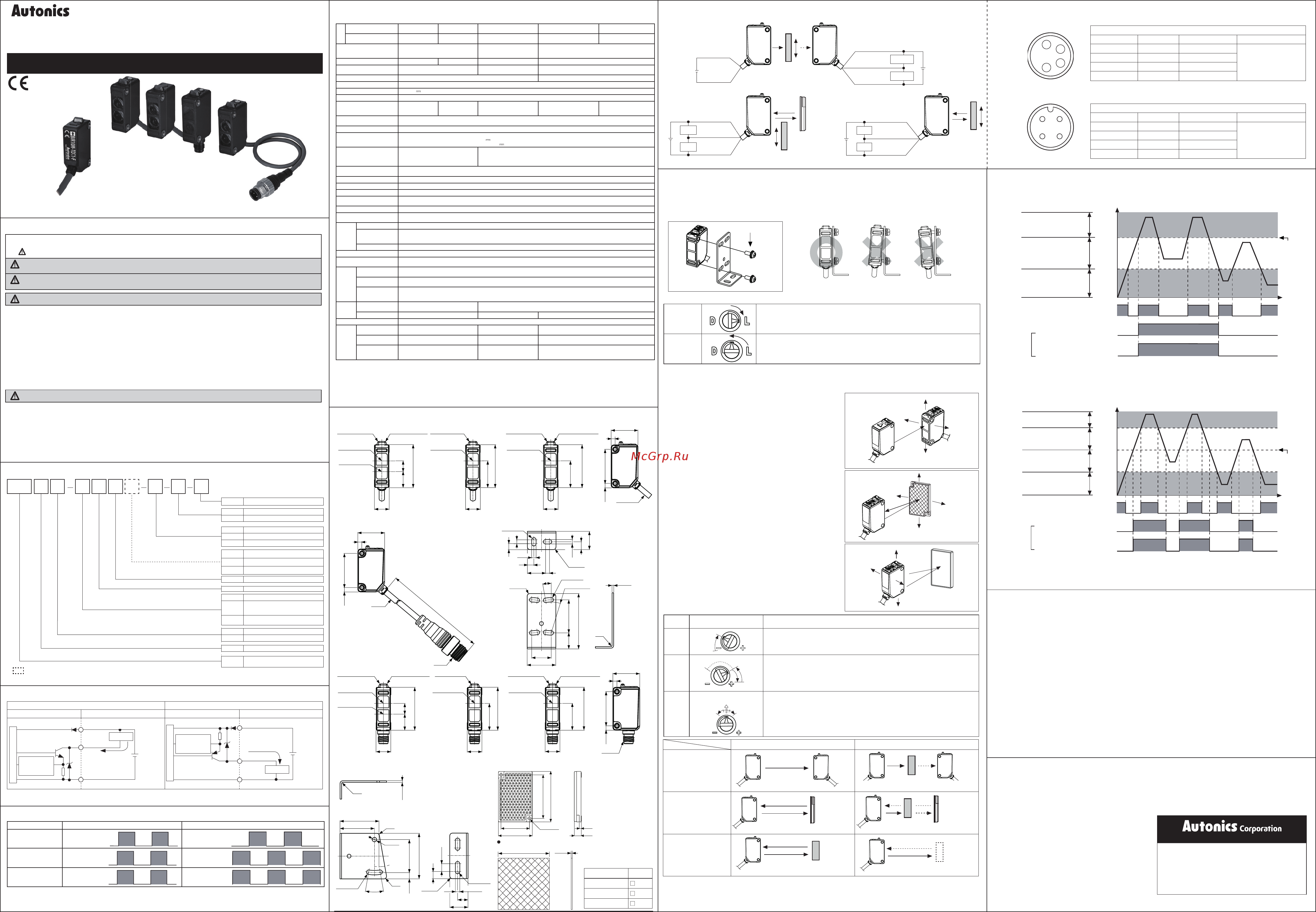
Autonics BJR3M-PDT-W-F Инструкция по эксплуатации онлайн
I N S T R U C T I O N M A N U A L
Thank you for choosing our Autonics product.
Please read the following safety considerations before use.
Connections for connector part
Optical axis adjustment
1. Place the emitter and the receiver facing each other and supply
the power.
2. After adjusting the position of the emitter and the receiver and
checking their stable indicating range, mount them in the middle
of the range.
3. After mounting this unit, check the operation of the sensor and
lighting of the stability indicator in both status. (none or sensing
target status)
※
If the sensing target is translucent body or smaller than Ø15mm, it
may not sense the target because light is passed.
※
Please set the sensitivity setting adjuster is executed in stable Light ON area and the reliability of environment (temperature,
supply, dust etc.) is increased after the mounting it in a stable area.
※
When adjusting sensitivity or switching operation modes, please use the Autonics adjustment screwdriver (accessory included).
Using a screwdriver with a bigger diameter than the adjuster buttons may cause errors when making adjustments.
※
It may cause breakdown when the sensitivity setting adjuster or the operation mode selection switch is turned by force.
1. Place the sensor and the refl ector (or refl ective tape) facing each
other and supply the power.
2. After adjusting the position of the sensor and refl ector (or refl ective
tape) and checking their stable indicating range, mount them in
the middle of the range. (none or sensing target status)
3. After mounting this unit, check the operation of the sensor and in
both status. (none or sensing target status)
※
Please use refl ective tape (MST Series) for where a refl ector can
not be installed.
1. Place the emitter and the receiver facing each other and supply
the power.
2. After adjusting the position of the emitter and the receiver and
checking their stable indicating range, mount them in the middle
of the range.
3. After mounting this unit, check the operation of the sensor and
lighting of the stability indicator in both status. (none or sensing
target status)
Through-beam type
Retroreflective type
Diffuse reflective type
Operation mode switching
※
For through-beam type, the switch is built-in the receiver.
Light ON
Turn the switch all the way to the right (towards L) to select Light ON operation.
Dark ON
Turn the switch all the way to the left (towards D) to select Dark ON operation.
Order Sensitivity setting Descriptions
1
(A)
From Light ON status, turn the sensitivity setting adjuster slowly to the right from
MIN sensitivity and check the position where operation indicator turns on (A).
2
(A)
(C)
(B)
From Dark ON status, turn the sensitivity setting adjuster further right and check
the position where the operation indicator turns on (B). Turn the adjuster left and
check the position where the operation indicator turns off (C).
※
If the operation indicator does not turn on at MAX sensitivity, the maximum
sensitivity setting is set at position (C).
3
Optimum sensitivity
(A) (C)
Set the adjuster at the center position between (A) and (C) for optimal sensitivity.
Also, check if the stability indicator turns off with or without the sensing target. If it
does not turn off, please review the operation mode again, as sensitivity may be
unstable.
※
1: The sensing distance is specifi ed with using the MS-2S refl ector. The distance between the sensor and the refl ector should be set
over 0.1m. When using reflective tapes, the reflectivity will vary by size of the tape. Please refer to the catalog or web site.
※
2: Non-glossy white paper 300×300mm.
※
3: Non-glossy white paper 100×100mm.
※
4: M8 connector cable is sold separately. (AWG26, core diameter: 0.52mm, number of cores: 20, insulator out diameter: Ø1mm)
※
5: M12 connector cable is sold separately. (AWG22, core diameter: 0.08mm, number of cores: 60, insulator out diameter: Ø1.65mm)
※
6: Cable type and cable connector type includes bracket A and connector type includes bracket B.
※
7: The weight includes packaging. The weight in parenthesis is for unit only.
※
The temperature or humidity mentioned in Environment indicates a non freezing or condensation.
Connector type
Модель A
MST-50-10
50
MST-100-5
100
MST-200-2
200
A
0.38
※
Connector pin
②
is N
.
C (Not Connected) terminal.
※
Connector pin
②
is N
.
C (Not Connected) terminal.
Connections for cable connector part
Connector pin No. Cable colors Functions Etc.
①
Brown Power Source (+V) Connector cable
(sold separately)
• CIDH4-
• CLDH4-
②
White N
.
C
③
Blue Power Source (0V)
④
Black Output
[M12 connector pin]
[M8 connector pin]
Sensitivity setting
※
The above specifi cations are subject to change and some models may be discontinued without notice.
※
Be sure to follow cautions written in the instruction manual and the technical descriptions (catalog, homepage).
※
The waveforms of 'Operation indicator' and 'Transistor output' are for Light ON operation.
The waveforms are reversed for Dark ON operation.
40.6
2-Ø3.8
52
60.4
2.5
8.5
34
+
-
Load
※
1
※
2
+
-
※
1
※
2
+
+
-
-
※
1
※
2
Cable connector type
12
43
3
4.5
4-R1.7
3.4
14
5
3
3.4
6
14
2-R2
8-R1.7
4-R23.7
4-10°
2-R2
42.5
25.4
12.3
15
22
(
R
)
1.2
1.2
(
R
)
R2
2-R1.7
20°
35
25.4
R2
Ø3.4
30
26.5
4.8
2-6
5.5
2-R2
2-3.4
4-R1.7
8
14
3
Ø4, 2 м
25.43.3
20
3
Ø4
M12
25.43.3
20
300
11
8
12
32
11
20
32
11
20
32
3
M8×1
25.43.3
20
1
2
4
3
Connections for cable connector part
Connector pin No. Cable colors Functions Etc.
①
Brown Power Source (+V) Connector cable
(sold separately)
• CIDH408-
• CLDH408-
②
White N
.
C
③
Blue Power Source (0V)
④
Black Output
Retrorefl ective/Diffuse refl ective type
Through-beam type
Stable light ON area
Unstable operation area
Stable light OFF area
Stability indicator
(green LED)
High
Incident
light
level
Low
ON
OFF
ON
OFF
ON
OFF
Operation
level
Operation indicator
(yellow LED)
Light ON
operation
Transistor output
Stable light ON area
Unstable light ON area
Unstable light OFF area
Stable light OFF area
Stability indicator
(green LED)
ON
OFF
High
Incident
light
level
Low
Operation
level
ON
OFF
ON
OFF
Operation indicator
(yellow LED)
Light ON
operation
Transistor output
BJR
Compact oil proof type
Photoelectric Sensor
Output type
Connection
Control output
Feature
Appearance
Power supply
Sensing type
Sensing distance unit
Sensing distance
Item
BJR 15 M T D T W P
※
This information is intended for product management of through-beam type.
(no need to refer when selecting model)
F
F Oil proof type
No mark
NPN open collector output
P PNP open collector output
No mark
Cable type
C Connector type
W Cable connector type
No mark
Integrated type
1 Emitter
2 Receiver
T Transistor output
D DC power
T Through-beam type
P
Retrorefl ective type
(built-in polarizing fi lter)
D Diffuse refl ective type
No mark
mm
M m
Number
Sensing distance
+
-
+
-
※
Install the sensor horizontally with the bracket.
Adjust Right/Left
Adjust Up/Down
Receiver
Emitter
Optic axis
Adjust Right/Left
Adjust Up/Down
Refl ector (MS-2S)
Refl ective tape
(MST series)
Adjust
Right/Left
Adjust Up/Down
Sensing target
Light ON Dark ON
Through-beam type
Emitter Receiver
Emitter Receiver
Sensing
target
Retrorefl ective type
Sensor
Refl ector (MS-2A)
Refl ective tape
(MST Series)
Refl ector (MS-2S)
Refl ective tape
(MST Series)
Sensing
target
Sensor
Diffuse refl ective type
Sensor
Sensing
target
Sensor
No sensing target
Thank you for choosing our Autonics product.
11
8
12
32
11
20
32
11
20
32
1. Follow instructions in 'Cautions during Use'. Otherwise, it may cause unexpected accidents.
2. When connecting a DC relay or other inductive load to the output, remove surge by using diodes or varistors.
3. Use the product, 0.5 sec after supplying power.
When using separate power supply for the sensor and load, supply power to sensor first.
4. 10-30VDC power supply should be insulated and limited voltage/current or Class 2, SELV power supply device.
5. Wire as short as possible and keep away from high voltage lines or power lines, to prevent inductive noise.
6. When using switching mode power supply to supply the power, ground F.G. terminal and connect a condenser between
0V and F.G. terminal to remove noise.
7. When using sensor with the equipment which generates noise (switching regulator, inverter, servo motor, etc.), ground F.G.
terminal of the equipment.
8. This unit may be used in the following environments.
①
Indoors (in the environment condition rated in 'Specifications')
②
Altitude max. 2,000m
③
Pollution degree 3
④
Installation category II
Compact Oil Proof Type Photoelectric Sensor
BJR-F SERIES
DRW161126AD
Warning
Safety Considerations
Caution
Ordering Information
Control Output Circuit Diagram
Specifi cations
Operation mode Light ON Dark ON
Receiver operation
Received light
Interrupted light
Received light
Interrupted light
Operation indicator
(yellow LED)
ON
OFF
ON
OFF
Transistor output
ON
OFF
ON
OFF
Operation Mode
Operating Timing Diagram
For mounting
When using the refl ective type photoelectric sensors closely over three units, it may result in malfunction due to mutual
interference. When using the through-beam type photoelectric sensors closely over two units, it may result in malfunction due
to mutual interference.
When installing the product, tighten the screw with a tightening torque of 0.5N
.
m.
M3×8mm
Installation and Sensitivity Adjustment
Major Products
Cautions during Use
Photoelectric Sensors Temperature Controllers
Fiber Optic Sensors Temperature/Humidity Transducers
Door Sensors SSRs/Power Controllers
Door Side Sensors Counters
Area Sensors Timers
Proximity Sensors Panel Meters
Pressure Sensors Tachometer/Pulse (Rate) Meters
Rotary Encoders Display Units
Connectors/Sockets Sensor Controllers
Switching Mode Power Supplies
Control Switches/Lamps/Buzzers
I/O Terminal Blocks & Cables
Stepper Motors/Drivers/Motion Controllers
Graphic/Logic Panels
Field Network Devices
Laser Marking System (Fiber, CO
₂
, Nd: YAG)
Laser Welding/Cutting System
http://www.autonics.com
HEADQUARTERS:
18, Bansong-ro 513 beon-gil, Haeundae-gu, Busan, South
Korea, 48002
TEL: 82-51-519-3232
E-mail: sales@autonics.com
DRW16112 6A D
Model
NPN open
collector output
BJR15M-TDT
- -F
BJR10M-TDT
- -F
BJR3M-PDT- -F BJR1M-DDT- -F BJR100-DDT- -F
PNP open
collector output
BJR15M-TDT
-
-P-F
BJR10M-TDT
- -P-F
BJR3M-PDT- -P-F BJR1M-DDT- -P-F BJR100-DDT- -P-F
Sensing type Through-beam type
Retrorefl ective type
(built-in polarizing fi lter)
Diffuse refl ective type
Sensing distance 15m 10m 3m
※
1
1m
※
2
100mm
※
3
Sensing target Opaque material over Ø12mm
Opaque material over Ø75mm
Translucent, opaque materials
Hysteresis
-
Max. 20% at sensing distance
Response time Max. 1ms
Power supply 10-30VDC
±10% (ripple P-P: max. 10%)
Current consumption Emitter / Receiver : max. 20mA
Max. 30mA
Light source
Infrared LED
(850nm)
Red LED
(660nm)
Red LED (660nm) Red LED (660nm) Infrared LED (850nm)
Sensitivity adjustment
Sensitivity adjuster
Operation mode Light ON / Dark ON selectable by switch
Control output
NPN or PNP open collector output
• Load voltage: max. 30VDC • Load current: max. 100mA • Residual voltage - NPN: max. 1VDC , PNP: max. 2VDC
Protection circuit
Power reverse polarity
protection circuit,
output short over current
protection circuit
Power reverse polarity protection circuit,
output short over current protection circuit,
interference prevention function
Indicator Operation indicator: yellow LED, stability indicator: green LED (emitter's power indicator: red LED)
Connection Cable type, connector type, cable connector type
Insulation resistance
Over 20MΩ (at 500VDC megger)
Noise immunity ±240V the square wave noise (pulse width: 1
㎲
) by the noise simulator
Dielectric strength 1,000VAC 50/60Hz for 1 minute
Vibration 1.5mm amplitude at frequency of 10 to 55Hz (for 1 min) in each X, Y, Z direction for 2 hours
Shock 500m/s
2
(approx. 50G) in each X, Y, Z direction for 3 times
Environ
ment
Ambient illu.
Sunlight: max. 11,000lx, incandescent lamp: max. 3,000lx (receiver illumination)
Ambient temp.
-25 to 60
℃
, storage: -40 to 70
℃
Ambient humi.
35 to 85%RH, storage: 35 to 85%RH
Protection structure IP67 (IEC standard), IP67F (JEM standard)
Material Case: acrylonitrile-butadiene-styrene, LED Cap: polyamide 12, sensing part: polymethyl methacrylate
Cable
Cable type
Ø4mm, 3-wire, 2m (emitter of through-beam type: Ø4mm, 2-wire, 2m)
(AWG26, core diameter: 0.52mm, number of cores: 20, insulator out diameter: Ø1mm)
Connector type
※4
M8 connector
Cable connector
type
※5
Ø4mm, 3-wire, 300mm (emitter of through-beam type: Ø4mm, 2-wire, 300mm), M12 connector
(AWG26, core diameter: 0.52mm, number of cores: 20, insulator out diameter: Ø1mm)
Acces-
sory
Common
Mounting bracket
※
6
, M3 bolt: 4,
adjustment screwdriver
Mounting bracket
※
6
, M3 bolt: 2, adjustment screwdriver
Individual
-
Refl ector (MS-2S)
-
Approval
Weight
※
7
Cable type Approx. 145g (approx. 95g)
Approx. 115g (approx. 50g)
Approx. 100g (approx. 50g)
Connector type
Approx. 65g (approx. 12g)
Approx. 75g (approx. 6g)
Approx. 60g (approx. 6g)
Cable connector
type
Approx. 105g (approx. 55g)
Approx. 95g (approx. 30g)
Approx. 80g (approx. 30g)
1. Fail-safe device must be installed when using the unit with machinery that may cause
serious injury or substantial economic loss. (e.g. nuclear power control, medical equipment, ships, vehicles,
railways, aircraft, combustion apparatus, safety
equipment, crime/disaster prevention devices, etc.)
Failure to follow this instruction may result in fi re, personal injury, or economic loss.
2. Do not disassemble or modify the unit.
Failure to follow this instruction may result in fi re.
3. Do not connect, repair, or inspect the unit while connected to a power source.
Failure to follow this instruction may result in fi re.
4. Check ‘Connections’ before wiring.
Failure to follow this instruction may result in fi re.
1. Use the unit within the rated specifi cations.
Failure to follow this instruction may result in fi re or product damage.
2. Use dry cloth to clean the unit, and do not use water or organic solvent.
Failure to follow this instruction may result in fi re.
3. Do not use the unit in the place where fl ammable/explosive/corrosive gas, humidity, direct
sunlight, radiant heat, vibration, impact, or salinity may be present.
Failure to follow this instruction may result in fi re or explosion.
※
Please observe all safety considerations for safe and proper product operation to avoid
hazards.
※
symbol represents caution due to special circumstances in which hazards may occur.
Warning
Failure to follow these instructions may result in serious injury or death.
Caution
Failure to follow these instructions may result in personal injury or product damage.
I N S T R U C T I O N M A N U A L
Thank you for choosing our Autonics product.
Please read the following safety considerations before use.
Connections for connector part
Optical axis adjustment
1. Place the emitter and the receiver facing each other and supply
the power.
2. After adjusting the position of the emitter and the receiver and
checking their stable indicating range, mount them in the middle
of the range.
3. After mounting this unit, check the operation of the sensor and
lighting of the stability indicator in both status. (none or sensing
target status)
※
If the sensing target is translucent body or smaller than Ø15mm, it
may not sense the target because light is passed.
※
Please set the sensitivity setting adjuster is executed in stable Light ON area and the reliability of environment (temperature,
supply, dust etc.) is increased after the mounting it in a stable area.
※
When adjusting sensitivity or switching operation modes, please use the Autonics adjustment screwdriver (accessory included).
Using a screwdriver with a bigger diameter than the adjuster buttons may cause errors when making adjustments.
※
It may cause breakdown when the sensitivity setting adjuster or the operation mode selection switch is turned by force.
1. Place the sensor and the refl ector (or refl ective tape) facing each
other and supply the power.
2. After adjusting the position of the sensor and refl ector (or refl ective
tape) and checking their stable indicating range, mount them in
the middle of the range. (none or sensing target status)
3. After mounting this unit, check the operation of the sensor and in
both status. (none or sensing target status)
※
Please use refl ective tape (MST Series) for where a refl ector can
not be installed.
1. Place the emitter and the receiver facing each other and supply
the power.
2. After adjusting the position of the emitter and the receiver and
checking their stable indicating range, mount them in the middle
of the range.
3. After mounting this unit, check the operation of the sensor and
lighting of the stability indicator in both status. (none or sensing
target status)
Through-beam type
Retroreflective type
Diffuse reflective type
Operation mode switching
※
For through-beam type, the switch is built-in the receiver.
Light ON
Turn the switch all the way to the right (towards L) to select Light ON operation.
Dark ON
Turn the switch all the way to the left (towards D) to select Dark ON operation.
Order Sensitivity setting Descriptions
1
(A)
From Light ON status, turn the sensitivity setting adjuster slowly to the right from
MIN sensitivity and check the position where operation indicator turns on (A).
2
(A)
(C)
(B)
From Dark ON status, turn the sensitivity setting adjuster further right and check
the position where the operation indicator turns on (B). Turn the adjuster left and
check the position where the operation indicator turns off (C).
※
If the operation indicator does not turn on at MAX sensitivity, the maximum
sensitivity setting is set at position (C).
3
Optimum sensitivity
(A) (C)
Set the adjuster at the center position between (A) and (C) for optimal sensitivity.
Also, check if the stability indicator turns off with or without the sensing target. If it
does not turn off, please review the operation mode again, as sensitivity may be
unstable.
※
1: The sensing distance is specifi ed with using the MS-2S refl ector. The distance between the sensor and the refl ector should be set
over 0.1m. When using reflective tapes, the reflectivity will vary by size of the tape. Please refer to the catalog or web site.
※
2: Non-glossy white paper 300×300mm.
※
3: Non-glossy white paper 100×100mm.
※
4: M8 connector cable is sold separately. (AWG26, core diameter: 0.52mm, number of cores: 20, insulator out diameter: Ø1mm)
※
5: M12 connector cable is sold separately. (AWG22, core diameter: 0.08mm, number of cores: 60, insulator out diameter: Ø1.65mm)
※
6: Cable type and cable connector type includes bracket A and connector type includes bracket B.
※
7: The weight includes packaging. The weight in parenthesis is for unit only.
※
The temperature or humidity mentioned in Environment indicates a non freezing or condensation.
Connector type
Модель A
MST-50-10 50
MST-100-5 100
MST-200-2 200
A
0.38
※
Connector pin
②
is N
.
C (Not Connected) terminal.
※
Connector pin
②
is N
.
C (Not Connected) terminal.
Connections for cable connector part
Connector pin No. Cable colors Functions Etc.
①
Brown Power Source (+V) Connector cable
(sold separately)
• CIDH4-
• CLDH4-
②
White N
.
C
③
Blue Power Source (0V)
④
Black Output
[M12 connector pin]
[M8 connector pin]
Sensitivity setting
※
The above specifi cations are subject to change and some models may be discontinued without notice.
※
Be sure to follow cautions written in the instruction manual and the technical descriptions (catalog, homepage).
※
The waveforms of 'Operation indicator' and 'Transistor output' are for Light ON operation.
The waveforms are reversed for Dark ON operation.
40.6
2-Ø3.8
52
60.4
2.5
8.5
34
+
-
Load
※
1
※
2
+
-
※
1
※
2
+
+
-
-
※
1
※
2
Cable connector type
12
43
3
4.5
4-R1.7
3.4
14
5
3
3.4
6
14
2-R2
8-R1.7
4-R23.7
4-10°
2-R2
42.5
25.4
12.3
15
22
(
R
)
1.2
1.2
(
R
)
R2
2-R1.7
20°
35
25.4
R2
Ø3.4
30
26.5
4.8
2-6
5.5
2-R2
2-3.4
4-R1.7
8
14
3
Ø4, 2 м
25.43.3
20
3
Ø4
M12
25.43.3
20
300
11
8
12
32
11
20
32
11
20
32
3
M8×1
25.43.3
20
1
2
4
3
Connections for cable connector part
Connector pin No. Cable colors Functions Etc.
①
Brown Power Source (+V) Connector cable
(sold separately)
• CIDH408-
• CLDH408-
②
White N
.
C
③
Blue Power Source (0V)
④
Black Output
Retrorefl ective/Diffuse refl ective type
Through-beam type
Stable light ON area
Unstable operation area
Stable light OFF area
Stability indicator
(green LED)
High
Incident
light
level
Low
ON
OFF
ON
OFF
ON
OFF
Operation
level
Operation indicator
(yellow LED)
Light ON
operation
Transistor output
Stable light ON area
Unstable light ON area
Unstable light OFF area
Stable light OFF area
Stability indicator
(green LED)
ON
OFF
High
Incident
light
level
Low
Operation
level
ON
OFF
ON
OFF
Operation indicator
(yellow LED)
Light ON
operation
Transistor output
BJR
Compact oil proof type
Photoelectric Sensor
Output type
Connection
Control output
Feature
Appearance
Power supply
Sensing type
Sensing distance unit
Sensing distance
Item
BJR 15 M T D T W P
※
This information is intended for product management of through-beam type.
(no need to refer when selecting model)
F
F Oil proof type
No mark
NPN open collector output
P PNP open collector output
No mark
Cable type
C Connector type
W Cable connector type
No mark
Integrated type
1 Emitter
2 Receiver
T Transistor output
D DC power
T Through-beam type
P
Retrorefl ective type
(built-in polarizing fi lter)
D Diffuse refl ective type
No mark
mm
M m
Number
Sensing distance
+
-
+
-
※
Install the sensor horizontally with the bracket.
Adjust Right/Left
Adjust Up/Down
Receiver
Emitter
Optic axis
Adjust Right/Left
Adjust Up/Down
Refl ector (MS-2S)
Refl ective tape
(MST series)
Adjust
Right/Left
Adjust Up/Down
Sensing target
Light ON Dark ON
Through-beam type
Emitter Receiver
Emitter Receiver
Sensing
target
Retrorefl ective type
Sensor
Refl ector (MS-2A)
Refl ective tape
(MST Series)
Refl ector (MS-2S)
Refl ective tape
(MST Series)
Sensing
target
Sensor
Diffuse refl ective type
Sensor
Sensing
target
Sensor
No sensing target
Thank you for choosing our Autonics product.
11
8
12
32
11
20
32
11
20
32
1. Follow instructions in 'Cautions during Use'. Otherwise, it may cause unexpected accidents.
2. When connecting a DC relay or other inductive load to the output, remove surge by using diodes or varistors.
3. Use the product, 0.5 sec after supplying power.
When using separate power supply for the sensor and load, supply power to sensor first.
4. 10-30VDC power supply should be insulated and limited voltage/current or Class 2, SELV power supply device.
5. Wire as short as possible and keep away from high voltage lines or power lines, to prevent inductive noise.
6. When using switching mode power supply to supply the power, ground F.G. terminal and connect a condenser between
0V and F.G. terminal to remove noise.
7. When using sensor with the equipment which generates noise (switching regulator, inverter, servo motor, etc.), ground F.G.
terminal of the equipment.
8. This unit may be used in the following environments.
①
Indoors (in the environment condition rated in 'Specifications')
②
Altitude max. 2,000m
③
Pollution degree 3
④
Installation category II
Compact Oil Proof Type Photoelectric Sensor
BJR-F SERIES
DRW161126AD
Warning
Safety Considerations
Caution
Ordering Information
Control Output Circuit Diagram
Specifi cations
Operation mode Light ON Dark ON
Receiver operation
Received light
Interrupted light
Received light
Interrupted light
Operation indicator
(yellow LED)
ON
OFF
ON
OFF
Transistor output
ON
OFF
ON
OFF
Operation Mode
Operating Timing Diagram
For mounting
When using the refl ective type photoelectric sensors closely over three units, it may result in malfunction due to mutual
interference. When using the through-beam type photoelectric sensors closely over two units, it may result in malfunction due
to mutual interference.
When installing the product, tighten the screw with a tightening torque of 0.5N
.
m.
M3×8mm
Installation and Sensitivity Adjustment
Major Products
Cautions during Use
Photoelectric Sensors Temperature Controllers
Fiber Optic Sensors Temperature/Humidity Transducers
Door Sensors SSRs/Power Controllers
Door Side Sensors Counters
Area Sensors Timers
Proximity Sensors Panel Meters
Pressure Sensors Tachometer/Pulse (Rate) Meters
Rotary Encoders Display Units
Connectors/Sockets Sensor Controllers
Switching Mode Power Supplies
Control Switches/Lamps/Buzzers
I/O Terminal Blocks & Cables
Stepper Motors/Drivers/Motion Controllers
Graphic/Logic Panels
Field Network Devices
Laser Marking System (Fiber, CO
₂
, Nd: YAG)
Laser Welding/Cutting System
http://www.autonics.com
HEADQUARTERS:
18, Bansong-ro 513 beon-gil, Haeundae-gu, Busan, South
Korea, 48002
TEL: 82-51-519-3232
E-mail: sales@autonics.com
DRW16112 6A D
Model
NPN open
collector output
BJR15M-TDT
- -F
BJR10M-TDT
- -F
BJR3M-PDT- -F BJR1M-DDT- -F BJR100-DDT- -F
PNP open
collector output
BJR15M-TDT
-
-P-F
BJR10M-TDT
- -P-F
BJR3M-PDT- -P-F BJR1M-DDT- -P-F BJR100-DDT- -P-F
Sensing type Through-beam type
Retrorefl ective type
(built-in polarizing fi lter)
Diffuse refl ective type
Sensing distance 15m 10m 3m
※
1
1m
※
2
100mm
※
3
Sensing target Opaque material over Ø12mm
Opaque material over Ø75mm
Translucent, opaque materials
Hysteresis
-
Max. 20% at sensing distance
Response time Max. 1ms
Power supply 10-30VDC
±10% (ripple P-P: max. 10%)
Current consumption Emitter / Receiver : max. 20mA
Max. 30mA
Light source
Infrared LED
(850nm)
Red LED
(660nm)
Red LED (660nm) Red LED (660nm) Infrared LED (850nm)
Sensitivity adjustment
Sensitivity adjuster
Operation mode Light ON / Dark ON selectable by switch
Control output
NPN or PNP open collector output
• Load voltage: max. 30VDC • Load current: max. 100mA • Residual voltage - NPN: max. 1VDC , PNP: max. 2VDC
Protection circuit
Power reverse polarity
protection circuit,
output short over current
protection circuit
Power reverse polarity protection circuit,
output short over current protection circuit,
interference prevention function
Indicator Operation indicator: yellow LED, stability indicator: green LED (emitter's power indicator: red LED)
Connection Cable type, connector type, cable connector type
Insulation resistance
Over 20MΩ (at 500VDC megger)
Noise immunity ±240V the square wave noise (pulse width: 1
㎲
) by the noise simulator
Dielectric strength 1,000VAC 50/60Hz for 1 minute
Vibration 1.5mm amplitude at frequency of 10 to 55Hz (for 1 min) in each X, Y, Z direction for 2 hours
Shock 500m/s
2
(approx. 50G) in each X, Y, Z direction for 3 times
Environ
ment
Ambient illu.
Sunlight: max. 11,000lx, incandescent lamp: max. 3,000lx (receiver illumination)
Ambient temp.
-25 to 60
℃
, storage: -40 to 70
℃
Ambient humi.
35 to 85%RH, storage: 35 to 85%RH
Protection structure IP67 (IEC standard), IP67F (JEM standard)
Material Case: acrylonitrile-butadiene-styrene, LED Cap: polyamide 12, sensing part: polymethyl methacrylate
Cable
Cable type
Ø4mm, 3-wire, 2m (emitter of through-beam type: Ø4mm, 2-wire, 2m)
(AWG26, core diameter: 0.52mm, number of cores: 20, insulator out diameter: Ø1mm)
Connector type
※4
M8 connector
Cable connector
type
※5
Ø4mm, 3-wire, 300mm (emitter of through-beam type: Ø4mm, 2-wire, 300mm), M12 connector
(AWG26, core diameter: 0.52mm, number of cores: 20, insulator out diameter: Ø1mm)
Acces-
sory
Common
Mounting bracket
※
6
, M3 bolt: 4,
adjustment screwdriver
Mounting bracket
※
6
, M3 bolt: 2, adjustment screwdriver
Individual
-
Refl ector (MS-2S)
-
Approval
Weight
※
7
Cable type Approx. 145g (approx. 95g)
Approx. 115g (approx. 50g)
Approx. 100g (approx. 50g)
Connector type
Approx. 65g (approx. 12g)
Approx. 75g (approx. 6g)
Approx. 60g (approx. 6g)
Cable connector
type
Approx. 105g (approx. 55g)
Approx. 95g (approx. 30g)
Approx. 80g (approx. 30g)
1. Fail-safe device must be installed when using the unit with machinery that may cause
serious injury or substantial economic loss. (e.g. nuclear power control, medical equipment, ships, vehicles,
railways, aircraft, combustion apparatus, safety
equipment, crime/disaster prevention devices, etc.)
Failure to follow this instruction may result in fi re, personal injury, or economic loss.
2. Do not disassemble or modify the unit.
Failure to follow this instruction may result in fi re.
3. Do not connect, repair, or inspect the unit while connected to a power source.
Failure to follow this instruction may result in fi re.
4. Check ‘Connections’ before wiring.
Failure to follow this instruction may result in fi re.
1. Use the unit within the rated specifi cations.
Failure to follow this instruction may result in fi re or product damage.
2. Use dry cloth to clean the unit, and do not use water or organic solvent.
Failure to follow this instruction may result in fi re.
3. Do not use the unit in the place where fl ammable/explosive/corrosive gas, humidity, direct
sunlight, radiant heat, vibration, impact, or salinity may be present.
Failure to follow this instruction may result in fi re or explosion.
※
Please observe all safety considerations for safe and proper product operation to avoid
hazards.
※
symbol represents caution due to special circumstances in which hazards may occur.
Warning
Failure to follow these instructions may result in serious injury or death.
Caution
Failure to follow these instructions may result in personal injury or product damage.
Компактный маслостойкий фотоэлектрический датчик
Серия BJR-F
РУКОВОДСТВО ПО ЭКСПЛУАТАЦИИ
I N S T R U C T I O N M A N U A L
Thank you for choosing our Autonics product.
Please read the following safety considerations before use.
Connections for connector part
Optical axis adjustment
1. Place the emitter and the receiver facing each other and supply
the power.
2. After adjusting the position of the emitter and the receiver and
checking their stable indicating range, mount them in the middle
of the range.
3. After mounting this unit, check the operation of the sensor and
lighting of the stability indicator in both status. (none or sensing
target status)
※
If the sensing target is translucent body or smaller than Ø15mm, it
may not sense the target because light is passed.
※
Please set the sensitivity setting adjuster is executed in stable Light ON area and the reliability of environment (temperature,
supply, dust etc.) is increased after the mounting it in a stable area.
※
When adjusting sensitivity or switching operation modes, please use the Autonics adjustment screwdriver (accessory included).
Using a screwdriver with a bigger diameter than the adjuster buttons may cause errors when making adjustments.
※
It may cause breakdown when the sensitivity setting adjuster or the operation mode selection switch is turned by force.
1. Place the sensor and the refl ector (or refl ective tape) facing each
other and supply the power.
2. After adjusting the position of the sensor and refl ector (or refl ective
tape) and checking their stable indicating range, mount them in
the middle of the range. (none or sensing target status)
3. After mounting this unit, check the operation of the sensor and in
both status. (none or sensing target status)
※
Please use refl ective tape (MST Series) for where a refl ector can
not be installed.
1. Place the emitter and the receiver facing each other and supply
the power.
2. After adjusting the position of the emitter and the receiver and
checking their stable indicating range, mount them in the middle
of the range.
3. After mounting this unit, check the operation of the sensor and
lighting of the stability indicator in both status. (none or sensing
target status)
Through-beam type
Retroreflective type
Diffuse reflective type
Operation mode switching
※
For through-beam type, the switch is built-in the receiver.
Light ON
Turn the switch all the way to the right (towards L) to select Light ON operation.
Dark ON
Turn the switch all the way to the left (towards D) to select Dark ON operation.
Order Sensitivity setting Descriptions
1
(A)
From Light ON status, turn the sensitivity setting adjuster slowly to the right from
MIN sensitivity and check the position where operation indicator turns on (A).
2
(A)
(C)
(B)
From Dark ON status, turn the sensitivity setting adjuster further right and check
the position where the operation indicator turns on (B). Turn the adjuster left and
check the position where the operation indicator turns off (C).
※
If the operation indicator does not turn on at MAX sensitivity, the maximum
sensitivity setting is set at position (C).
3
Optimum sensitivity
(A) (C)
Set the adjuster at the center position between (A) and (C) for optimal sensitivity.
Also, check if the stability indicator turns off with or without the sensing target. If it
does not turn off, please review the operation mode again, as sensitivity may be
unstable.
※
1: The sensing distance is specifi ed with using the MS-2S refl ector. The distance between the sensor and the refl ector should be set
over 0.1m. When using reflective tapes, the reflectivity will vary by size of the tape. Please refer to the catalog or web site.
※
2: Non-glossy white paper 300×300mm.
※
3: Non-glossy white paper 100×100mm.
※
4: M8 connector cable is sold separately. (AWG26, core diameter: 0.52mm, number of cores: 20, insulator out diameter: Ø1mm)
※
5: M12 connector cable is sold separately. (AWG22, core diameter: 0.08mm, number of cores: 60, insulator out diameter: Ø1.65mm)
※
6: Cable type and cable connector type includes bracket A and connector type includes bracket B.
※
7: The weight includes packaging. The weight in parenthesis is for unit only.
※
The temperature or humidity mentioned in Environment indicates a non freezing or condensation.
Connector type
Модель A
MST-50-10 50
MST-100-5 100
MST-200-2 200
A
0.38
※
Connector pin
②
is N
.
C (Not Connected) terminal.
※
Connector pin
②
is N
.
C (Not Connected) terminal.
Connections for cable connector part
Connector pin No. Cable colors Functions Etc.
①
Brown Power Source (+V) Connector cable
(sold separately)
• CIDH4-
• CLDH4-
②
White N
.
C
③
Blue Power Source (0V)
④
Black Output
[M12 connector pin]
[M8 connector pin]
Sensitivity setting
※
The above specifi cations are subject to change and some models may be discontinued without notice.
※
Be sure to follow cautions written in the instruction manual and the technical descriptions (catalog, homepage).
※
The waveforms of 'Operation indicator' and 'Transistor output' are for Light ON operation.
The waveforms are reversed for Dark ON operation.
40.6
2-Ø3.8
52
60.4
2.5
8.5
34
+
-
Load
※
1
※
2
+
-
※
1
※
2
+
+
-
-
※
1
※
2
Cable connector type
12
43
3
4.5
4-R1.7
3.4
14
5
3
3.4
6
14
2-R2
8-R1.7
4-R23.7
4-10°
2-R2
42.5
25.4
12.3
15
22
(
R
)
1.2
1.2
(
R
)
R2
2-R1.7
20°
35
25.4
R2
Ø3.4
30
26.5
4.8
2-6
5.5
2-R2
2-3.4
4-R1.7
8
14
3
Ø4, 2 м
25.43.3
20
3
Ø4
M12
25.43.3
20
300
11
8
12
32
11
20
32
11
20
32
3
M8×1
25.43.3
20
1
2
4
3
Connections for cable connector part
Connector pin No. Cable colors Functions Etc.
①
Brown Power Source (+V) Connector cable
(sold separately)
• CIDH408-
• CLDH408-
②
White N
.
C
③
Blue Power Source (0V)
④
Black Output
Retrorefl ective/Diffuse refl ective type
Through-beam type
Stable light ON area
Unstable operation area
Stable light OFF area
Stability indicator
(green LED)
High
Incident
light
level
Low
ON
OFF
ON
OFF
ON
OFF
Operation
level
Operation indicator
(yellow LED)
Light ON
operation
Transistor output
Stable light ON area
Unstable light ON area
Unstable light OFF area
Stable light OFF area
Stability indicator
(green LED)
ON
OFF
High
Incident
light
level
Low
Operation
level
ON
OFF
ON
OFF
Operation indicator
(yellow LED)
Light ON
operation
Transistor output
BJR
Compact oil proof type
Photoelectric Sensor
Output type
Connection
Control output
Feature
Appearance
Power supply
Sensing type
Sensing distance unit
Sensing distance
Item
BJR 15 M T D T W P
※
This information is intended for product management of through-beam type.
(no need to refer when selecting model)
F
F Oil proof type
No mark
NPN open collector output
P PNP open collector output
No mark
Cable type
C Connector type
W Cable connector type
No mark
Integrated type
1 Emitter
2 Receiver
T Transistor output
D DC power
T Through-beam type
P
Retrorefl ective type
(built-in polarizing fi lter)
D Diffuse refl ective type
No mark
mm
M m
Number
Sensing distance
+
-
+
-
※
Install the sensor horizontally with the bracket.
Adjust Right/Left
Adjust Up/Down
Receiver
Emitter
Optic axis
Adjust Right/Left
Adjust Up/Down
Refl ector (MS-2S)
Refl ective tape
(MST series)
Adjust
Right/Left
Adjust Up/Down
Sensing target
Light ON Dark ON
Through-beam type
Emitter Receiver
Emitter Receiver
Sensing
target
Retrorefl ective type
Sensor
Refl ector (MS-2A)
Refl ective tape
(MST Series)
Refl ector (MS-2S)
Refl ective tape
(MST Series)
Sensing
target
Sensor
Diffuse refl ective type
Sensor
Sensing
target
Sensor
No sensing target
Thank you for choosing our Autonics product.
11
8
12
32
11
20
32
11
20
32
1. Follow instructions in 'Cautions during Use'. Otherwise, it may cause unexpected accidents.
2. When connecting a DC relay or other inductive load to the output, remove surge by using diodes or varistors.
3. Use the product, 0.5 sec after supplying power.
When using separate power supply for the sensor and load, supply power to sensor first.
4. 10-30VDC power supply should be insulated and limited voltage/current or Class 2, SELV power supply device.
5. Wire as short as possible and keep away from high voltage lines or power lines, to prevent inductive noise.
6. When using switching mode power supply to supply the power, ground F.G. terminal and connect a condenser between
0V and F.G. terminal to remove noise.
7. When using sensor with the equipment which generates noise (switching regulator, inverter, servo motor, etc.), ground F.G.
terminal of the equipment.
8. This unit may be used in the following environments.
①
Indoors (in the environment condition rated in 'Specifications')
②
Altitude max. 2,000m
③
Pollution degree 3
④
Installation category II
Compact Oil Proof Type Photoelectric Sensor
BJR-F SERIES
DRW161126AD
Warning
Safety Considerations
Caution
Ordering Information
Control Output Circuit Diagram
Specifi cations
Operation mode Light ON Dark ON
Receiver operation
Received light
Interrupted light
Received light
Interrupted light
Operation indicator
(yellow LED)
ON
OFF
ON
OFF
Transistor output
ON
OFF
ON
OFF
Operation Mode
Operating Timing Diagram
For mounting
When using the refl ective type photoelectric sensors closely over three units, it may result in malfunction due to mutual
interference. When using the through-beam type photoelectric sensors closely over two units, it may result in malfunction due
to mutual interference.
When installing the product, tighten the screw with a tightening torque of 0.5N
.
m.
M3×8mm
Installation and Sensitivity Adjustment
Major Products
Cautions during Use
Photoelectric Sensors Temperature Controllers
Fiber Optic Sensors Temperature/Humidity Transducers
Door Sensors SSRs/Power Controllers
Door Side Sensors Counters
Area Sensors Timers
Proximity Sensors Panel Meters
Pressure Sensors Tachometer/Pulse (Rate) Meters
Rotary Encoders Display Units
Connectors/Sockets Sensor Controllers
Switching Mode Power Supplies
Control Switches/Lamps/Buzzers
I/O Terminal Blocks & Cables
Stepper Motors/Drivers/Motion Controllers
Graphic/Logic Panels
Field Network Devices
Laser Marking System (Fiber, CO
₂
, Nd: YAG)
Laser Welding/Cutting System
http://www.autonics.com
HEADQUARTERS:
18, Bansong-ro 513 beon-gil, Haeundae-gu, Busan, South
Korea, 48002
TEL: 82-51-519-3232
E-mail: sales@autonics.com
DRW16112 6A D
Model
NPN open
collector output
BJR15M-TDT
- -F
BJR10M-TDT
- -F
BJR3M-PDT- -F BJR1M-DDT- -F BJR100-DDT- -F
PNP open
collector output
BJR15M-TDT
-
-P-F
BJR10M-TDT
- -P-F
BJR3M-PDT- -P-F BJR1M-DDT- -P-F BJR100-DDT- -P-F
Sensing type Through-beam type
Retrorefl ective type
(built-in polarizing fi lter)
Diffuse refl ective type
Sensing distance 15m 10m 3m
※
1
1m
※
2
100mm
※
3
Sensing target Opaque material over Ø12mm
Opaque material over Ø75mm
Translucent, opaque materials
Hysteresis
-
Max. 20% at sensing distance
Response time Max. 1ms
Power supply 10-30VDC
±10% (ripple P-P: max. 10%)
Current consumption Emitter / Receiver : max. 20mA
Max. 30mA
Light source
Infrared LED
(850nm)
Red LED
(660nm)
Red LED (660nm) Red LED (660nm) Infrared LED (850nm)
Sensitivity adjustment
Sensitivity adjuster
Operation mode Light ON / Dark ON selectable by switch
Control output
NPN or PNP open collector output
• Load voltage: max. 30VDC • Load current: max. 100mA • Residual voltage - NPN: max. 1VDC , PNP: max. 2VDC
Protection circuit
Power reverse polarity
protection circuit,
output short over current
protection circuit
Power reverse polarity protection circuit,
output short over current protection circuit,
interference prevention function
Indicator Operation indicator: yellow LED, stability indicator: green LED (emitter's power indicator: red LED)
Connection Cable type, connector type, cable connector type
Insulation resistance
Over 20MΩ (at 500VDC megger)
Noise immunity ±240V the square wave noise (pulse width: 1
㎲
) by the noise simulator
Dielectric strength 1,000VAC 50/60Hz for 1 minute
Vibration 1.5mm amplitude at frequency of 10 to 55Hz (for 1 min) in each X, Y, Z direction for 2 hours
Shock 500m/s
2
(approx. 50G) in each X, Y, Z direction for 3 times
Environ
ment
Ambient illu.
Sunlight: max. 11,000lx, incandescent lamp: max. 3,000lx (receiver illumination)
Ambient temp.
-25 to 60
℃
, storage: -40 to 70
℃
Ambient humi.
35 to 85%RH, storage: 35 to 85%RH
Protection structure IP67 (IEC standard), IP67F (JEM standard)
Material Case: acrylonitrile-butadiene-styrene, LED Cap: polyamide 12, sensing part: polymethyl methacrylate
Cable
Cable type
Ø4mm, 3-wire, 2m (emitter of through-beam type: Ø4mm, 2-wire, 2m)
(AWG26, core diameter: 0.52mm, number of cores: 20, insulator out diameter: Ø1mm)
Connector type
※4
M8 connector
Cable connector
type
※5
Ø4mm, 3-wire, 300mm (emitter of through-beam type: Ø4mm, 2-wire, 300mm), M12 connector
(AWG26, core diameter: 0.52mm, number of cores: 20, insulator out diameter: Ø1mm)
Acces-
sory
Common
Mounting bracket
※
6
, M3 bolt: 4,
adjustment screwdriver
Mounting bracket
※
6
, M3 bolt: 2, adjustment screwdriver
Individual
-
Refl ector (MS-2S)
-
Approval
Weight
※
7
Cable type Approx. 145g (approx. 95g)
Approx. 115g (approx. 50g)
Approx. 100g (approx. 50g)
Connector type
Approx. 65g (approx. 12g)
Approx. 75g (approx. 6g)
Approx. 60g (approx. 6g)
Cable connector
type
Approx. 105g (approx. 55g)
Approx. 95g (approx. 30g)
Approx. 80g (approx. 30g)
1. Fail-safe device must be installed when using the unit with machinery that may cause
serious injury or substantial economic loss. (e.g. nuclear power control, medical equipment, ships, vehicles,
railways, aircraft, combustion apparatus, safety
equipment, crime/disaster prevention devices, etc.)
Failure to follow this instruction may result in fi re, personal injury, or economic loss.
2. Do not disassemble or modify the unit.
Failure to follow this instruction may result in fi re.
3. Do not connect, repair, or inspect the unit while connected to a power source.
Failure to follow this instruction may result in fi re.
4. Check ‘Connections’ before wiring.
Failure to follow this instruction may result in fi re.
1. Use the unit within the rated specifi cations.
Failure to follow this instruction may result in fi re or product damage.
2. Use dry cloth to clean the unit, and do not use water or organic solvent.
Failure to follow this instruction may result in fi re.
3. Do not use the unit in the place where fl ammable/explosive/corrosive gas, humidity, direct
sunlight, radiant heat, vibration, impact, or salinity may be present.
Failure to follow this instruction may result in fi re or explosion.
※
Please observe all safety considerations for safe and proper product operation to avoid
hazards.
※
symbol represents caution due to special circumstances in which hazards may occur.
Warning
Failure to follow these instructions may result in serious injury or death.
Caution
Failure to follow these instructions may result in personal injury or product damage.
Ú Для обеспечения надежной и безопасной эксплуатации данного устройства неукоснительно выполняйте указания
по технике безопасности.
Ú Этот знак указывает на особые обстоятельства, при которых может возникнуть опасность.
Внимание Несоблюдение данных указаний может привести к несчастному случаю, в том числе со
смертельным исходом.
Осторожно Несоблюдение данных условий может привести к несчастному случаю или повреждению
изделия.
Внимание
1. При использовании данного устройства в составе механизмов, при эксплуатации которых существует
опасность получения серьезных травм или значительного повреждения оборудования, следует
использовать отказоустойчивые устройства защиты (к такому оборудованию относятся, например,
атомные электростанции, медицинское оборудование, морские суда, наземные транспортные
средства, железнодорожный транспорт, воздушные суда, устройства внутреннего сгорания, устройства
безопасности, предохранительное/противоаварийное оборудование и т.п.).
Невыполнение данного указания может привести к возгоранию, несчастному случаю или материальному ущербу.
2. Запрещается разбирать или модифицировать устройство.
Ошибочное подключение может привести к возгоранию.
3. Перед подключением электрических цепей, ремонтом или проверкой устройство следует отключить от
электрической сети.
Ошибочное подключение может привести к возгоранию.
4. Подключение устройства следует выполнять согласно указаниям раздела «Подключение».
Ошибочное подключение может привести к возгоранию.
Осторожно
1. Во время эксплуатации следует соблюдать номинальные параметры, указанные в техническом паспорте
изделия.
В противном случае существует опасность возгорания или повреждения оборудования.
2. Для очистки устройства следует использовать сухую ветошь; запрещается использовать воду или
органические растворители.
Ошибочное подключение может привести к возгоранию.
3. Запрещается использовать устройство в средах, содержащих воспламеняемые, взрывоопасные или
коррозионно-активные газы и соли, а также во влажных средах и в местах с прямым воздействием
солнечного излучения, тепла, вибрации и ударных нагрузок.
Несоблюдение этих указаний может привести к возгоранию или взрыву.
Благодарим за выбор продукции Autonics.
Перед началом эксплуатации устройства ознакомьтесь с указаниями по технике безопасности.
Указания по технике безопасности
Информация для оформления заказа
Подключение
Режим
Тип выходного сигнала
Электропитание
Тип срабатывания
Единицы измерения расстояния срабатывания
Расстояние срабатывания
Тип устройства
Управляющий
выход
Особенности
F Маслостойкий корпус
Без обозн.
Выход NPN с открытым коллектором
P Выход PNP с открытым коллектором
Без обозн.
Исполнение с кабелем
С Исполнение с разъемом
w Исполнение с разъемом на кабеле
Без обозн.
Комбинированный
1 Излучатель
2 Приемник
T Транзисторный выход
D Источник постоянного тока
T На просвет
P
Датчик с обратным отражением
(с встроенным поляризационным
фильтром)
D
Датчик с диффузионным
отражением
Без обозн.
мм
M мин
Кол-во Расстояние срабатывания
BJR
Компактный маслостойкий
фотоэлектрический датчик
Цепь выхода управления
Режим работы
Данная информация относится к устройству, срабатывающему на просвет
(при выборе модели указывать тип устройства не требуется)
I N S T R U C T I O N M A N U A L
Thank you for choosing our Autonics product.
Please read the following safety considerations before use.
Connections for connector part
Optical axis adjustment
1. Place the emitter and the receiver facing each other and supply
the power.
2. After adjusting the position of the emitter and the receiver and
checking their stable indicating range, mount them in the middle
of the range.
3. After mounting this unit, check the operation of the sensor and
lighting of the stability indicator in both status. (none or sensing
target status)
※
If the sensing target is translucent body or smaller than Ø15mm, it
may not sense the target because light is passed.
※
Please set the sensitivity setting adjuster is executed in stable Light ON area and the reliability of environment (temperature,
supply, dust etc.) is increased after the mounting it in a stable area.
※
When adjusting sensitivity or switching operation modes, please use the Autonics adjustment screwdriver (accessory included).
Using a screwdriver with a bigger diameter than the adjuster buttons may cause errors when making adjustments.
※
It may cause breakdown when the sensitivity setting adjuster or the operation mode selection switch is turned by force.
1. Place the sensor and the refl ector (or refl ective tape) facing each
other and supply the power.
2. After adjusting the position of the sensor and refl ector (or refl ective
tape) and checking their stable indicating range, mount them in
the middle of the range. (none or sensing target status)
3. After mounting this unit, check the operation of the sensor and in
both status. (none or sensing target status)
※
Please use refl ective tape (MST Series) for where a refl ector can
not be installed.
1. Place the emitter and the receiver facing each other and supply
the power.
2. After adjusting the position of the emitter and the receiver and
checking their stable indicating range, mount them in the middle
of the range.
3. After mounting this unit, check the operation of the sensor and
lighting of the stability indicator in both status. (none or sensing
target status)
Through-beam type
Retroreflective type
Diffuse reflective type
Operation mode switching
※
For through-beam type, the switch is built-in the receiver.
Light ON
Turn the switch all the way to the right (towards L) to select Light ON operation.
Dark ON
Turn the switch all the way to the left (towards D) to select Dark ON operation.
Order Sensitivity setting Descriptions
1
(A)
From Light ON status, turn the sensitivity setting adjuster slowly to the right from
MIN sensitivity and check the position where operation indicator turns on (A).
2
(A)
(C)
(B)
From Dark ON status, turn the sensitivity setting adjuster further right and check
the position where the operation indicator turns on (B). Turn the adjuster left and
check the position where the operation indicator turns off (C).
※
If the operation indicator does not turn on at MAX sensitivity, the maximum
sensitivity setting is set at position (C).
3
Optimum sensitivity
(A) (C)
Set the adjuster at the center position between (A) and (C) for optimal sensitivity.
Also, check if the stability indicator turns off with or without the sensing target. If it
does not turn off, please review the operation mode again, as sensitivity may be
unstable.
※
1: The sensing distance is specifi ed with using the MS-2S refl ector. The distance between the sensor and the refl ector should be set
over 0.1m. When using reflective tapes, the reflectivity will vary by size of the tape. Please refer to the catalog or web site.
※
2: Non-glossy white paper 300×300mm.
※
3: Non-glossy white paper 100×100mm.
※
4: M8 connector cable is sold separately. (AWG26, core diameter: 0.52mm, number of cores: 20, insulator out diameter: Ø1mm)
※
5: M12 connector cable is sold separately. (AWG22, core diameter: 0.08mm, number of cores: 60, insulator out diameter: Ø1.65mm)
※
6: Cable type and cable connector type includes bracket A and connector type includes bracket B.
※
7: The weight includes packaging. The weight in parenthesis is for unit only.
※
The temperature or humidity mentioned in Environment indicates a non freezing or condensation.
Connector type
Модель A
MST-50-10 50
MST-100-5 100
MST-200-2 200
A
0.38
※
Connector pin
②
is N
.
C (Not Connected) terminal.
※
Connector pin
②
is N
.
C (Not Connected) terminal.
Connections for cable connector part
Connector pin No. Cable colors Functions Etc.
①
Brown Power Source (+V) Connector cable
(sold separately)
• CIDH4-
• CLDH4-
②
White N
.
C
③
Blue Power Source (0V)
④
Black Output
[M12 connector pin]
[M8 connector pin]
Sensitivity setting
※
The above specifi cations are subject to change and some models may be discontinued without notice.
※
Be sure to follow cautions written in the instruction manual and the technical descriptions (catalog, homepage).
※
The waveforms of 'Operation indicator' and 'Transistor output' are for Light ON operation.
The waveforms are reversed for Dark ON operation.
40.6
2-Ø3.8
52
60.4
2.5
8.5
34
+
-
Load
※
1
※
2
+
-
※
1
※
2
+
+
-
-
※
1
※
2
Cable connector type
12
43
3
4.5
4-R1.7
3.4
14
5
3
3.4
6
14
2-R2
8-R1.7
4-R23.7
4-10°
2-R2
42.5
25.4
12.3
15
22
(
R
)
1.2
1.2
(
R
)
R2
2-R1.7
20°
35
25.4
R2
Ø3.4
30
26.5
4.8
2-6
5.5
2-R2
2-3.4
4-R1.7
8
14
3
Ø4, 2 м
25.43.3
20
3
Ø4
M12
25.43.3
20
300
11
8
12
32
11
20
32
11
20
32
3
M8×1
25.43.3
20
1
2
4
3
Connections for cable connector part
Connector pin No. Cable colors Functions Etc.
①
Brown Power Source (+V) Connector cable
(sold separately)
• CIDH408-
• CLDH408-
②
White N
.
C
③
Blue Power Source (0V)
④
Black Output
Retrorefl ective/Diffuse refl ective type
Through-beam type
Stable light ON area
Unstable operation area
Stable light OFF area
Stability indicator
(green LED)
High
Incident
light
level
Low
ON
OFF
ON
OFF
ON
OFF
Operation
level
Operation indicator
(yellow LED)
Light ON
operation
Transistor output
Stable light ON area
Unstable light ON area
Unstable light OFF area
Stable light OFF area
Stability indicator
(green LED)
ON
OFF
High
Incident
light
level
Low
Operation
level
ON
OFF
ON
OFF
Operation indicator
(yellow LED)
Light ON
operation
Transistor output
BJR
Compact oil proof type
Photoelectric Sensor
Output type
Connection
Control output
Feature
Appearance
Power supply
Sensing type
Sensing distance unit
Sensing distance
Item
BJR 15 M T D T W P
※
This information is intended for product management of through-beam type.
(no need to refer when selecting model)
F
F Oil proof type
No mark
NPN open collector output
P PNP open collector output
No mark
Cable type
C Connector type
W Cable connector type
No mark
Integrated type
1 Emitter
2 Receiver
T Transistor output
D DC power
T Through-beam type
P
Retrorefl ective type
(built-in polarizing fi lter)
D Diffuse refl ective type
No mark
mm
M m
Number
Sensing distance
+
-
+
-
※
Install the sensor horizontally with the bracket.
Adjust Right/Left
Adjust Up/Down
Receiver
Emitter
Optic axis
Adjust Right/Left
Adjust Up/Down
Refl ector (MS-2S)
Refl ective tape
(MST series)
Adjust
Right/Left
Adjust Up/Down
Sensing target
Light ON Dark ON
Through-beam type
Emitter Receiver
Emitter Receiver
Sensing
target
Retrorefl ective type
Sensor
Refl ector (MS-2A)
Refl ective tape
(MST Series)
Refl ector (MS-2S)
Refl ective tape
(MST Series)
Sensing
target
Sensor
Diffuse refl ective type
Sensor
Sensing
target
Sensor
No sensing target
Thank you for choosing our Autonics product.
11
8
12
32
11
20
32
11
20
32
1. Follow instructions in 'Cautions during Use'. Otherwise, it may cause unexpected accidents.
2. When connecting a DC relay or other inductive load to the output, remove surge by using diodes or varistors.
3. Use the product, 0.5 sec after supplying power.
When using separate power supply for the sensor and load, supply power to sensor first.
4. 10-30VDC power supply should be insulated and limited voltage/current or Class 2, SELV power supply device.
5. Wire as short as possible and keep away from high voltage lines or power lines, to prevent inductive noise.
6. When using switching mode power supply to supply the power, ground F.G. terminal and connect a condenser between
0V and F.G. terminal to remove noise.
7. When using sensor with the equipment which generates noise (switching regulator, inverter, servo motor, etc.), ground F.G.
terminal of the equipment.
8. This unit may be used in the following environments.
①
Indoors (in the environment condition rated in 'Specifications')
②
Altitude max. 2,000m
③
Pollution degree 3
④
Installation category II
Compact Oil Proof Type Photoelectric Sensor
BJR-F SERIES
DRW161126AD
Warning
Safety Considerations
Caution
Ordering Information
Control Output Circuit Diagram
Specifi cations
Operation mode Light ON Dark ON
Receiver operation
Received light
Interrupted light
Received light
Interrupted light
Operation indicator
(yellow LED)
ON
OFF
ON
OFF
Transistor output
ON
OFF
ON
OFF
Operation Mode
Operating Timing Diagram
For mounting
When using the refl ective type photoelectric sensors closely over three units, it may result in malfunction due to mutual
interference. When using the through-beam type photoelectric sensors closely over two units, it may result in malfunction due
to mutual interference.
When installing the product, tighten the screw with a tightening torque of 0.5N
.
m.
M3×8mm
Installation and Sensitivity Adjustment
Major Products
Cautions during Use
Photoelectric Sensors Temperature Controllers
Fiber Optic Sensors Temperature/Humidity Transducers
Door Sensors SSRs/Power Controllers
Door Side Sensors Counters
Area Sensors Timers
Proximity Sensors Panel Meters
Pressure Sensors Tachometer/Pulse (Rate) Meters
Rotary Encoders Display Units
Connectors/Sockets Sensor Controllers
Switching Mode Power Supplies
Control Switches/Lamps/Buzzers
I/O Terminal Blocks & Cables
Stepper Motors/Drivers/Motion Controllers
Graphic/Logic Panels
Field Network Devices
Laser Marking System (Fiber, CO
₂
, Nd: YAG)
Laser Welding/Cutting System
http://www.autonics.com
HEADQUARTERS:
18, Bansong-ro 513 beon-gil, Haeundae-gu, Busan, South
Korea, 48002
TEL: 82-51-519-3232
E-mail: sales@autonics.com
DRW16112 6A D
Model
NPN open
collector output
BJR15M-TDT
- -F
BJR10M-TDT
- -F
BJR3M-PDT- -F BJR1M-DDT- -F BJR100-DDT- -F
PNP open
collector output
BJR15M-TDT
-
-P-F
BJR10M-TDT
- -P-F
BJR3M-PDT- -P-F BJR1M-DDT- -P-F BJR100-DDT- -P-F
Sensing type Through-beam type
Retrorefl ective type
(built-in polarizing fi lter)
Diffuse refl ective type
Sensing distance 15m 10m 3m
※
1
1m
※
2
100mm
※
3
Sensing target Opaque material over Ø12mm
Opaque material over Ø75mm
Translucent, opaque materials
Hysteresis
-
Max. 20% at sensing distance
Response time Max. 1ms
Power supply 10-30VDC
±10% (ripple P-P: max. 10%)
Current consumption Emitter / Receiver : max. 20mA
Max. 30mA
Light source
Infrared LED
(850nm)
Red LED
(660nm)
Red LED (660nm) Red LED (660nm) Infrared LED (850nm)
Sensitivity adjustment
Sensitivity adjuster
Operation mode Light ON / Dark ON selectable by switch
Control output
NPN or PNP open collector output
• Load voltage: max. 30VDC • Load current: max. 100mA • Residual voltage - NPN: max. 1VDC , PNP: max. 2VDC
Protection circuit
Power reverse polarity
protection circuit,
output short over current
protection circuit
Power reverse polarity protection circuit,
output short over current protection circuit,
interference prevention function
Indicator Operation indicator: yellow LED, stability indicator: green LED (emitter's power indicator: red LED)
Connection Cable type, connector type, cable connector type
Insulation resistance
Over 20MΩ (at 500VDC megger)
Noise immunity ±240V the square wave noise (pulse width: 1
㎲
) by the noise simulator
Dielectric strength 1,000VAC 50/60Hz for 1 minute
Vibration 1.5mm amplitude at frequency of 10 to 55Hz (for 1 min) in each X, Y, Z direction for 2 hours
Shock 500m/s
2
(approx. 50G) in each X, Y, Z direction for 3 times
Environ
ment
Ambient illu.
Sunlight: max. 11,000lx, incandescent lamp: max. 3,000lx (receiver illumination)
Ambient temp.
-25 to 60
℃
, storage: -40 to 70
℃
Ambient humi.
35 to 85%RH, storage: 35 to 85%RH
Protection structure IP67 (IEC standard), IP67F (JEM standard)
Material Case: acrylonitrile-butadiene-styrene, LED Cap: polyamide 12, sensing part: polymethyl methacrylate
Cable
Cable type
Ø4mm, 3-wire, 2m (emitter of through-beam type: Ø4mm, 2-wire, 2m)
(AWG26, core diameter: 0.52mm, number of cores: 20, insulator out diameter: Ø1mm)
Connector type
※4
M8 connector
Cable connector
type
※5
Ø4mm, 3-wire, 300mm (emitter of through-beam type: Ø4mm, 2-wire, 300mm), M12 connector
(AWG26, core diameter: 0.52mm, number of cores: 20, insulator out diameter: Ø1mm)
Acces-
sory
Common
Mounting bracket
※
6
, M3 bolt: 4,
adjustment screwdriver
Mounting bracket
※
6
, M3 bolt: 2, adjustment screwdriver
Individual
-
Refl ector (MS-2S)
-
Approval
Weight
※
7
Cable type Approx. 145g (approx. 95g)
Approx. 115g (approx. 50g)
Approx. 100g (approx. 50g)
Connector type
Approx. 65g (approx. 12g)
Approx. 75g (approx. 6g)
Approx. 60g (approx. 6g)
Cable connector
type
Approx. 105g (approx. 55g)
Approx. 95g (approx. 30g)
Approx. 80g (approx. 30g)
1. Fail-safe device must be installed when using the unit with machinery that may cause
serious injury or substantial economic loss. (e.g. nuclear power control, medical equipment, ships, vehicles,
railways, aircraft, combustion apparatus, safety
equipment, crime/disaster prevention devices, etc.)
Failure to follow this instruction may result in fi re, personal injury, or economic loss.
2. Do not disassemble or modify the unit.
Failure to follow this instruction may result in fi re.
3. Do not connect, repair, or inspect the unit while connected to a power source.
Failure to follow this instruction may result in fi re.
4. Check ‘Connections’ before wiring.
Failure to follow this instruction may result in fi re.
1. Use the unit within the rated specifi cations.
Failure to follow this instruction may result in fi re or product damage.
2. Use dry cloth to clean the unit, and do not use water or organic solvent.
Failure to follow this instruction may result in fi re.
3. Do not use the unit in the place where fl ammable/explosive/corrosive gas, humidity, direct
sunlight, radiant heat, vibration, impact, or salinity may be present.
Failure to follow this instruction may result in fi re or explosion.
※
Please observe all safety considerations for safe and proper product operation to avoid
hazards.
※
symbol represents caution due to special circumstances in which hazards may occur.
Warning
Failure to follow these instructions may result in serious injury or death.
Caution
Failure to follow these instructions may result in personal injury or product damage.
Выход NPN с открытым коллектором Выход PNP с открытым коллектором
Схема фотоэлектри. датчика Схема фотоэлектр. датчикаПодключение
(коричневый) + В
Нагрузка
Нагрузка
(черный) Выход
(синий) 0 В
Макс. 100 мА
Макс. 100 мА
10-30 В=
10-30 В=
(синий) 0 В
(черный) Выход
(коричневый) + В
Защита выходной
цепи от короткого
замыкания и
превышения тока
Защита выходной
цепи от короткого
замыкания и
превышения тока
Главная цепь
Главная цепь
Подключение
Ú При возникновении короткого замыкания на выходе или превышении параметров питания, срабатывает защита
выходной цепи от короткого замыкания или превышения тока и нормальный выходной сигнал не формируется.
Режим работы На свет На затемнение
Режим работы
приемника
Свет поступает
I N S T R U C T I O N M A N U A L
Thank you for choosing our Autonics product.
Please read the following safety considerations before use.
Connections for connector part
Optical axis adjustment
1. Place the emitter and the receiver facing each other and supply
the power.
2. After adjusting the position of the emitter and the receiver and
checking their stable indicating range, mount them in the middle
of the range.
3. After mounting this unit, check the operation of the sensor and
lighting of the stability indicator in both status. (none or sensing
target status)
※
If the sensing target is translucent body or smaller than Ø15mm, it
may not sense the target because light is passed.
※
Please set the sensitivity setting adjuster is executed in stable Light ON area and the reliability of environment (temperature,
supply, dust etc.) is increased after the mounting it in a stable area.
※
When adjusting sensitivity or switching operation modes, please use the Autonics adjustment screwdriver (accessory included).
Using a screwdriver with a bigger diameter than the adjuster buttons may cause errors when making adjustments.
※
It may cause breakdown when the sensitivity setting adjuster or the operation mode selection switch is turned by force.
1. Place the sensor and the refl ector (or refl ective tape) facing each
other and supply the power.
2. After adjusting the position of the sensor and refl ector (or refl ective
tape) and checking their stable indicating range, mount them in
the middle of the range. (none or sensing target status)
3. After mounting this unit, check the operation of the sensor and in
both status. (none or sensing target status)
※
Please use refl ective tape (MST Series) for where a refl ector can
not be installed.
1. Place the emitter and the receiver facing each other and supply
the power.
2. After adjusting the position of the emitter and the receiver and
checking their stable indicating range, mount them in the middle
of the range.
3. After mounting this unit, check the operation of the sensor and
lighting of the stability indicator in both status. (none or sensing
target status)
Through-beam type
Retroreflective type
Diffuse reflective type
Operation mode switching
※
For through-beam type, the switch is built-in the receiver.
Light ON
Turn the switch all the way to the right (towards L) to select Light ON operation.
Dark ON
Turn the switch all the way to the left (towards D) to select Dark ON operation.
Order Sensitivity setting Descriptions
1
(A)
From Light ON status, turn the sensitivity setting adjuster slowly to the right from
MIN sensitivity and check the position where operation indicator turns on (A).
2
(A)
(C)
(B)
From Dark ON status, turn the sensitivity setting adjuster further right and check
the position where the operation indicator turns on (B). Turn the adjuster left and
check the position where the operation indicator turns off (C).
※
If the operation indicator does not turn on at MAX sensitivity, the maximum
sensitivity setting is set at position (C).
3
Optimum sensitivity
(A) (C)
Set the adjuster at the center position between (A) and (C) for optimal sensitivity.
Also, check if the stability indicator turns off with or without the sensing target. If it
does not turn off, please review the operation mode again, as sensitivity may be
unstable.
※
1: The sensing distance is specifi ed with using the MS-2S refl ector. The distance between the sensor and the refl ector should be set
over 0.1m. When using reflective tapes, the reflectivity will vary by size of the tape. Please refer to the catalog or web site.
※
2: Non-glossy white paper 300×300mm.
※
3: Non-glossy white paper 100×100mm.
※
4: M8 connector cable is sold separately. (AWG26, core diameter: 0.52mm, number of cores: 20, insulator out diameter: Ø1mm)
※
5: M12 connector cable is sold separately. (AWG22, core diameter: 0.08mm, number of cores: 60, insulator out diameter: Ø1.65mm)
※
6: Cable type and cable connector type includes bracket A and connector type includes bracket B.
※
7: The weight includes packaging. The weight in parenthesis is for unit only.
※
The temperature or humidity mentioned in Environment indicates a non freezing or condensation.
Connector type
Модель A
MST-50-10 50
MST-100-5 100
MST-200-2 200
A
0.38
※
Connector pin
②
is N
.
C (Not Connected) terminal.
※
Connector pin
②
is N
.
C (Not Connected) terminal.
Connections for cable connector part
Connector pin No. Cable colors Functions Etc.
①
Brown Power Source (+V) Connector cable
(sold separately)
• CIDH4-
• CLDH4-
②
White N
.
C
③
Blue Power Source (0V)
④
Black Output
[M12 connector pin]
[M8 connector pin]
Sensitivity setting
※
The above specifi cations are subject to change and some models may be discontinued without notice.
※
Be sure to follow cautions written in the instruction manual and the technical descriptions (catalog, homepage).
※
The waveforms of 'Operation indicator' and 'Transistor output' are for Light ON operation.
The waveforms are reversed for Dark ON operation.
40.6
2-Ø3.8
52
60.4
2.5
8.5
34
+
-
Load
※
1
※
2
+
-
※
1
※
2
+
+
-
-
※
1
※
2
Cable connector type
12
43
3
4.5
4-R1.7
3.4
14
5
3
3.4
6
14
2-R2
8-R1.7
4-R23.7
4-10°
2-R2
42.5
25.4
12.3
15
22
(
R
)
1.2
1.2
(
R
)
R2
2-R1.7
20°
35
25.4
R2
Ø3.4
30
26.5
4.8
2-6
5.5
2-R2
2-3.4
4-R1.7
8
14
3
Ø4, 2 м
25.43.3
20
3
Ø4
M12
25.43.3
20
300
11
8
12
32
11
20
32
11
20
32
3
M8×1
25.43.3
20
1
2
4
3
Connections for cable connector part
Connector pin No. Cable colors Functions Etc.
①
Brown Power Source (+V) Connector cable
(sold separately)
• CIDH408-
• CLDH408-
②
White N
.
C
③
Blue Power Source (0V)
④
Black Output
Retrorefl ective/Diffuse refl ective type
Through-beam type
Stable light ON area
Unstable operation area
Stable light OFF area
Stability indicator
(green LED)
High
Incident
light
level
Low
ON
OFF
ON
OFF
ON
OFF
Operation
level
Operation indicator
(yellow LED)
Light ON
operation
Transistor output
Stable light ON area
Unstable light ON area
Unstable light OFF area
Stable light OFF area
Stability indicator
(green LED)
ON
OFF
High
Incident
light
level
Low
Operation
level
ON
OFF
ON
OFF
Operation indicator
(yellow LED)
Light ON
operation
Transistor output
BJR
Compact oil proof type
Photoelectric Sensor
Output type
Connection
Control output
Feature
Appearance
Power supply
Sensing type
Sensing distance unit
Sensing distance
Item
BJR 15 M T D T W P
※
This information is intended for product management of through-beam type.
(no need to refer when selecting model)
F
F Oil proof type
No mark
NPN open collector output
P PNP open collector output
No mark
Cable type
C Connector type
W Cable connector type
No mark
Integrated type
1 Emitter
2 Receiver
T Transistor output
D DC power
T Through-beam type
P
Retrorefl ective type
(built-in polarizing fi lter)
D Diffuse refl ective type
No mark
mm
M m
Number
Sensing distance
+
-
+
-
※
Install the sensor horizontally with the bracket.
Adjust Right/Left
Adjust Up/Down
Receiver
Emitter
Optic axis
Adjust Right/Left
Adjust Up/Down
Refl ector (MS-2S)
Refl ective tape
(MST series)
Adjust
Right/Left
Adjust Up/Down
Sensing target
Light ON Dark ON
Through-beam type
Emitter Receiver
Emitter Receiver
Sensing
target
Retrorefl ective type
Sensor
Refl ector (MS-2A)
Refl ective tape
(MST Series)
Refl ector (MS-2S)
Refl ective tape
(MST Series)
Sensing
target
Sensor
Diffuse refl ective type
Sensor
Sensing
target
Sensor
No sensing target
Thank you for choosing our Autonics product.
11
8
12
32
11
20
32
11
20
32
1. Follow instructions in 'Cautions during Use'. Otherwise, it may cause unexpected accidents.
2. When connecting a DC relay or other inductive load to the output, remove surge by using diodes or varistors.
3. Use the product, 0.5 sec after supplying power.
When using separate power supply for the sensor and load, supply power to sensor first.
4. 10-30VDC power supply should be insulated and limited voltage/current or Class 2, SELV power supply device.
5. Wire as short as possible and keep away from high voltage lines or power lines, to prevent inductive noise.
6. When using switching mode power supply to supply the power, ground F.G. terminal and connect a condenser between
0V and F.G. terminal to remove noise.
7. When using sensor with the equipment which generates noise (switching regulator, inverter, servo motor, etc.), ground F.G.
terminal of the equipment.
8. This unit may be used in the following environments.
①
Indoors (in the environment condition rated in 'Specifications')
②
Altitude max. 2,000m
③
Pollution degree 3
④
Installation category II
Compact Oil Proof Type Photoelectric Sensor
BJR-F SERIES
DRW161126AD
Warning
Safety Considerations
Caution
Ordering Information
Control Output Circuit Diagram
Specifi cations
Operation mode Light ON Dark ON
Receiver operation
Received light
Interrupted light
Received light
Interrupted light
Operation indicator
(yellow LED)
ON
OFF
ON
OFF
Transistor output
ON
OFF
ON
OFF
Operation Mode
Operating Timing Diagram
For mounting
When using the refl ective type photoelectric sensors closely over three units, it may result in malfunction due to mutual
interference. When using the through-beam type photoelectric sensors closely over two units, it may result in malfunction due
to mutual interference.
When installing the product, tighten the screw with a tightening torque of 0.5N
.
m.
M3×8mm
Installation and Sensitivity Adjustment
Major Products
Cautions during Use
Photoelectric Sensors Temperature Controllers
Fiber Optic Sensors Temperature/Humidity Transducers
Door Sensors SSRs/Power Controllers
Door Side Sensors Counters
Area Sensors Timers
Proximity Sensors Panel Meters
Pressure Sensors Tachometer/Pulse (Rate) Meters
Rotary Encoders Display Units
Connectors/Sockets Sensor Controllers
Switching Mode Power Supplies
Control Switches/Lamps/Buzzers
I/O Terminal Blocks & Cables
Stepper Motors/Drivers/Motion Controllers
Graphic/Logic Panels
Field Network Devices
Laser Marking System (Fiber, CO
₂
, Nd: YAG)
Laser Welding/Cutting System
http://www.autonics.com
HEADQUARTERS:
18, Bansong-ro 513 beon-gil, Haeundae-gu, Busan, South
Korea, 48002
TEL: 82-51-519-3232
E-mail: sales@autonics.com
DRW16112 6A D
Model
NPN open
collector output
BJR15M-TDT
- -F
BJR10M-TDT
- -F
BJR3M-PDT- -F BJR1M-DDT- -F BJR100-DDT- -F
PNP open
collector output
BJR15M-TDT
-
-P-F
BJR10M-TDT
- -P-F
BJR3M-PDT- -P-F BJR1M-DDT- -P-F BJR100-DDT- -P-F
Sensing type Through-beam type
Retrorefl ective type
(built-in polarizing fi lter)
Diffuse refl ective type
Sensing distance 15m 10m 3m
※
1
1m
※
2
100mm
※
3
Sensing target Opaque material over Ø12mm
Opaque material over Ø75mm
Translucent, opaque materials
Hysteresis
-
Max. 20% at sensing distance
Response time Max. 1ms
Power supply 10-30VDC
±10% (ripple P-P: max. 10%)
Current consumption Emitter / Receiver : max. 20mA
Max. 30mA
Light source
Infrared LED
(850nm)
Red LED
(660nm)
Red LED (660nm) Red LED (660nm) Infrared LED (850nm)
Sensitivity adjustment
Sensitivity adjuster
Operation mode Light ON / Dark ON selectable by switch
Control output
NPN or PNP open collector output
• Load voltage: max. 30VDC • Load current: max. 100mA • Residual voltage - NPN: max. 1VDC , PNP: max. 2VDC
Protection circuit
Power reverse polarity
protection circuit,
output short over current
protection circuit
Power reverse polarity protection circuit,
output short over current protection circuit,
interference prevention function
Indicator Operation indicator: yellow LED, stability indicator: green LED (emitter's power indicator: red LED)
Connection Cable type, connector type, cable connector type
Insulation resistance
Over 20MΩ (at 500VDC megger)
Noise immunity ±240V the square wave noise (pulse width: 1
㎲
) by the noise simulator
Dielectric strength 1,000VAC 50/60Hz for 1 minute
Vibration 1.5mm amplitude at frequency of 10 to 55Hz (for 1 min) in each X, Y, Z direction for 2 hours
Shock 500m/s
2
(approx. 50G) in each X, Y, Z direction for 3 times
Environ
ment
Ambient illu.
Sunlight: max. 11,000lx, incandescent lamp: max. 3,000lx (receiver illumination)
Ambient temp.
-25 to 60
℃
, storage: -40 to 70
℃
Ambient humi.
35 to 85%RH, storage: 35 to 85%RH
Protection structure IP67 (IEC standard), IP67F (JEM standard)
Material Case: acrylonitrile-butadiene-styrene, LED Cap: polyamide 12, sensing part: polymethyl methacrylate
Cable
Cable type
Ø4mm, 3-wire, 2m (emitter of through-beam type: Ø4mm, 2-wire, 2m)
(AWG26, core diameter: 0.52mm, number of cores: 20, insulator out diameter: Ø1mm)
Connector type
※4
M8 connector
Cable connector
type
※5
Ø4mm, 3-wire, 300mm (emitter of through-beam type: Ø4mm, 2-wire, 300mm), M12 connector
(AWG26, core diameter: 0.52mm, number of cores: 20, insulator out diameter: Ø1mm)
Acces-
sory
Common
Mounting bracket
※
6
, M3 bolt: 4,
adjustment screwdriver
Mounting bracket
※
6
, M3 bolt: 2, adjustment screwdriver
Individual
-
Refl ector (MS-2S)
-
Approval
Weight
※
7
Cable type Approx. 145g (approx. 95g)
Approx. 115g (approx. 50g)
Approx. 100g (approx. 50g)
Connector type
Approx. 65g (approx. 12g)
Approx. 75g (approx. 6g)
Approx. 60g (approx. 6g)
Cable connector
type
Approx. 105g (approx. 55g)
Approx. 95g (approx. 30g)
Approx. 80g (approx. 30g)
1. Fail-safe device must be installed when using the unit with machinery that may cause
serious injury or substantial economic loss. (e.g. nuclear power control, medical equipment, ships, vehicles,
railways, aircraft, combustion apparatus, safety
equipment, crime/disaster prevention devices, etc.)
Failure to follow this instruction may result in fi re, personal injury, or economic loss.
2. Do not disassemble or modify the unit.
Failure to follow this instruction may result in fi re.
3. Do not connect, repair, or inspect the unit while connected to a power source.
Failure to follow this instruction may result in fi re.
4. Check ‘Connections’ before wiring.
Failure to follow this instruction may result in fi re.
1. Use the unit within the rated specifi cations.
Failure to follow this instruction may result in fi re or product damage.
2. Use dry cloth to clean the unit, and do not use water or organic solvent.
Failure to follow this instruction may result in fi re.
3. Do not use the unit in the place where fl ammable/explosive/corrosive gas, humidity, direct
sunlight, radiant heat, vibration, impact, or salinity may be present.
Failure to follow this instruction may result in fi re or explosion.
※
Please observe all safety considerations for safe and proper product operation to avoid
hazards.
※
symbol represents caution due to special circumstances in which hazards may occur.
Warning
Failure to follow these instructions may result in serious injury or death.
Caution
Failure to follow these instructions may result in personal injury or product damage.
Свет не поступает Свет не поступает
Индикатор
срабатывания
(желтый светодиод)
ВКЛ
I N S T R U C T I O N M A N U A L
Thank you for choosing our Autonics product.
Please read the following safety considerations before use.
Connections for connector part
Optical axis adjustment
1. Place the emitter and the receiver facing each other and supply
the power.
2. After adjusting the position of the emitter and the receiver and
checking their stable indicating range, mount them in the middle
of the range.
3. After mounting this unit, check the operation of the sensor and
lighting of the stability indicator in both status. (none or sensing
target status)
※
If the sensing target is translucent body or smaller than Ø15mm, it
may not sense the target because light is passed.
※
Please set the sensitivity setting adjuster is executed in stable Light ON area and the reliability of environment (temperature,
supply, dust etc.) is increased after the mounting it in a stable area.
※
When adjusting sensitivity or switching operation modes, please use the Autonics adjustment screwdriver (accessory included).
Using a screwdriver with a bigger diameter than the adjuster buttons may cause errors when making adjustments.
※
It may cause breakdown when the sensitivity setting adjuster or the operation mode selection switch is turned by force.
1. Place the sensor and the refl ector (or refl ective tape) facing each
other and supply the power.
2. After adjusting the position of the sensor and refl ector (or refl ective
tape) and checking their stable indicating range, mount them in
the middle of the range. (none or sensing target status)
3. After mounting this unit, check the operation of the sensor and in
both status. (none or sensing target status)
※
Please use refl ective tape (MST Series) for where a refl ector can
not be installed.
1. Place the emitter and the receiver facing each other and supply
the power.
2. After adjusting the position of the emitter and the receiver and
checking their stable indicating range, mount them in the middle
of the range.
3. After mounting this unit, check the operation of the sensor and
lighting of the stability indicator in both status. (none or sensing
target status)
Through-beam type
Retroreflective type
Diffuse reflective type
Operation mode switching
※
For through-beam type, the switch is built-in the receiver.
Light ON
Turn the switch all the way to the right (towards L) to select Light ON operation.
Dark ON
Turn the switch all the way to the left (towards D) to select Dark ON operation.
Order Sensitivity setting Descriptions
1
(A)
From Light ON status, turn the sensitivity setting adjuster slowly to the right from
MIN sensitivity and check the position where operation indicator turns on (A).
2
(A)
(C)
(B)
From Dark ON status, turn the sensitivity setting adjuster further right and check
the position where the operation indicator turns on (B). Turn the adjuster left and
check the position where the operation indicator turns off (C).
※
If the operation indicator does not turn on at MAX sensitivity, the maximum
sensitivity setting is set at position (C).
3
Optimum sensitivity
(A) (C)
Set the adjuster at the center position between (A) and (C) for optimal sensitivity.
Also, check if the stability indicator turns off with or without the sensing target. If it
does not turn off, please review the operation mode again, as sensitivity may be
unstable.
※
1: The sensing distance is specifi ed with using the MS-2S refl ector. The distance between the sensor and the refl ector should be set
over 0.1m. When using reflective tapes, the reflectivity will vary by size of the tape. Please refer to the catalog or web site.
※
2: Non-glossy white paper 300×300mm.
※
3: Non-glossy white paper 100×100mm.
※
4: M8 connector cable is sold separately. (AWG26, core diameter: 0.52mm, number of cores: 20, insulator out diameter: Ø1mm)
※
5: M12 connector cable is sold separately. (AWG22, core diameter: 0.08mm, number of cores: 60, insulator out diameter: Ø1.65mm)
※
6: Cable type and cable connector type includes bracket A and connector type includes bracket B.
※
7: The weight includes packaging. The weight in parenthesis is for unit only.
※
The temperature or humidity mentioned in Environment indicates a non freezing or condensation.
Connector type
Модель A
MST-50-10 50
MST-100-5 100
MST-200-2 200
A
0.38
※
Connector pin
②
is N
.
C (Not Connected) terminal.
※
Connector pin
②
is N
.
C (Not Connected) terminal.
Connections for cable connector part
Connector pin No. Cable colors Functions Etc.
①
Brown Power Source (+V) Connector cable
(sold separately)
• CIDH4-
• CLDH4-
②
White N
.
C
③
Blue Power Source (0V)
④
Black Output
[M12 connector pin]
[M8 connector pin]
Sensitivity setting
※
The above specifi cations are subject to change and some models may be discontinued without notice.
※
Be sure to follow cautions written in the instruction manual and the technical descriptions (catalog, homepage).
※
The waveforms of 'Operation indicator' and 'Transistor output' are for Light ON operation.
The waveforms are reversed for Dark ON operation.
40.6
2-Ø3.8
52
60.4
2.5
8.5
34
+
-
Load
※
1
※
2
+
-
※
1
※
2
+
+
-
-
※
1
※
2
Cable connector type
12
43
3
4.5
4-R1.7
3.4
14
5
3
3.4
6
14
2-R2
8-R1.7
4-R23.7
4-10°
2-R2
42.5
25.4
12.3
15
22
(
R
)
1.2
1.2
(
R
)
R2
2-R1.7
20°
35
25.4
R2
Ø3.4
30
26.5
4.8
2-6
5.5
2-R2
2-3.4
4-R1.7
8
14
3
Ø4, 2 м
25.43.3
20
3
Ø4
M12
25.43.3
20
300
11
8
12
32
11
20
32
11
20
32
3
M8×1
25.43.3
20
1
2
4
3
Connections for cable connector part
Connector pin No. Cable colors Functions Etc.
①
Brown Power Source (+V) Connector cable
(sold separately)
• CIDH408-
• CLDH408-
②
White N
.
C
③
Blue Power Source (0V)
④
Black Output
Retrorefl ective/Diffuse refl ective type
Through-beam type
Stable light ON area
Unstable operation area
Stable light OFF area
Stability indicator
(green LED)
High
Incident
light
level
Low
ON
OFF
ON
OFF
ON
OFF
Operation
level
Operation indicator
(yellow LED)
Light ON
operation
Transistor output
Stable light ON area
Unstable light ON area
Unstable light OFF area
Stable light OFF area
Stability indicator
(green LED)
ON
OFF
High
Incident
light
level
Low
Operation
level
ON
OFF
ON
OFF
Operation indicator
(yellow LED)
Light ON
operation
Transistor output
BJR
Compact oil proof type
Photoelectric Sensor
Output type
Connection
Control output
Feature
Appearance
Power supply
Sensing type
Sensing distance unit
Sensing distance
Item
BJR 15 M T D T W P
※
This information is intended for product management of through-beam type.
(no need to refer when selecting model)
F
F Oil proof type
No mark
NPN open collector output
P PNP open collector output
No mark
Cable type
C Connector type
W Cable connector type
No mark
Integrated type
1 Emitter
2 Receiver
T Transistor output
D DC power
T Through-beam type
P
Retrorefl ective type
(built-in polarizing fi lter)
D Diffuse refl ective type
No mark
mm
M m
Number
Sensing distance
+
-
+
-
※
Install the sensor horizontally with the bracket.
Adjust Right/Left
Adjust Up/Down
Receiver
Emitter
Optic axis
Adjust Right/Left
Adjust Up/Down
Refl ector (MS-2S)
Refl ective tape
(MST series)
Adjust
Right/Left
Adjust Up/Down
Sensing target
Light ON Dark ON
Through-beam type
Emitter Receiver
Emitter Receiver
Sensing
target
Retrorefl ective type
Sensor
Refl ector (MS-2A)
Refl ective tape
(MST Series)
Refl ector (MS-2S)
Refl ective tape
(MST Series)
Sensing
target
Sensor
Diffuse refl ective type
Sensor
Sensing
target
Sensor
No sensing target
Thank you for choosing our Autonics product.
11
8
12
32
11
20
32
11
20
32
1. Follow instructions in 'Cautions during Use'. Otherwise, it may cause unexpected accidents.
2. When connecting a DC relay or other inductive load to the output, remove surge by using diodes or varistors.
3. Use the product, 0.5 sec after supplying power.
When using separate power supply for the sensor and load, supply power to sensor first.
4. 10-30VDC power supply should be insulated and limited voltage/current or Class 2, SELV power supply device.
5. Wire as short as possible and keep away from high voltage lines or power lines, to prevent inductive noise.
6. When using switching mode power supply to supply the power, ground F.G. terminal and connect a condenser between
0V and F.G. terminal to remove noise.
7. When using sensor with the equipment which generates noise (switching regulator, inverter, servo motor, etc.), ground F.G.
terminal of the equipment.
8. This unit may be used in the following environments.
①
Indoors (in the environment condition rated in 'Specifications')
②
Altitude max. 2,000m
③
Pollution degree 3
④
Installation category II
Compact Oil Proof Type Photoelectric Sensor
BJR-F SERIES
DRW161126AD
Warning
Safety Considerations
Caution
Ordering Information
Control Output Circuit Diagram
Specifi cations
Operation mode Light ON Dark ON
Receiver operation
Received light
Interrupted light
Received light
Interrupted light
Operation indicator
(yellow LED)
ON
OFF
ON
OFF
Transistor output
ON
OFF
ON
OFF
Operation Mode
Operating Timing Diagram
For mounting
When using the refl ective type photoelectric sensors closely over three units, it may result in malfunction due to mutual
interference. When using the through-beam type photoelectric sensors closely over two units, it may result in malfunction due
to mutual interference.
When installing the product, tighten the screw with a tightening torque of 0.5N
.
m.
M3×8mm
Installation and Sensitivity Adjustment
Major Products
Cautions during Use
Photoelectric Sensors Temperature Controllers
Fiber Optic Sensors Temperature/Humidity Transducers
Door Sensors SSRs/Power Controllers
Door Side Sensors Counters
Area Sensors Timers
Proximity Sensors Panel Meters
Pressure Sensors Tachometer/Pulse (Rate) Meters
Rotary Encoders Display Units
Connectors/Sockets Sensor Controllers
Switching Mode Power Supplies
Control Switches/Lamps/Buzzers
I/O Terminal Blocks & Cables
Stepper Motors/Drivers/Motion Controllers
Graphic/Logic Panels
Field Network Devices
Laser Marking System (Fiber, CO
₂
, Nd: YAG)
Laser Welding/Cutting System
http://www.autonics.com
HEADQUARTERS:
18, Bansong-ro 513 beon-gil, Haeundae-gu, Busan, South
Korea, 48002
TEL: 82-51-519-3232
E-mail: sales@autonics.com
DRW16112 6A D
Model
NPN open
collector output
BJR15M-TDT
- -F
BJR10M-TDT
- -F
BJR3M-PDT- -F BJR1M-DDT- -F BJR100-DDT- -F
PNP open
collector output
BJR15M-TDT
-
-P-F
BJR10M-TDT
- -P-F
BJR3M-PDT- -P-F BJR1M-DDT- -P-F BJR100-DDT- -P-F
Sensing type Through-beam type
Retrorefl ective type
(built-in polarizing fi lter)
Diffuse refl ective type
Sensing distance 15m 10m 3m
※
1
1m
※
2
100mm
※
3
Sensing target Opaque material over Ø12mm
Opaque material over Ø75mm
Translucent, opaque materials
Hysteresis
-
Max. 20% at sensing distance
Response time Max. 1ms
Power supply 10-30VDC
±10% (ripple P-P: max. 10%)
Current consumption Emitter / Receiver : max. 20mA
Max. 30mA
Light source
Infrared LED
(850nm)
Red LED
(660nm)
Red LED (660nm) Red LED (660nm) Infrared LED (850nm)
Sensitivity adjustment
Sensitivity adjuster
Operation mode Light ON / Dark ON selectable by switch
Control output
NPN or PNP open collector output
• Load voltage: max. 30VDC • Load current: max. 100mA • Residual voltage - NPN: max. 1VDC , PNP: max. 2VDC
Protection circuit
Power reverse polarity
protection circuit,
output short over current
protection circuit
Power reverse polarity protection circuit,
output short over current protection circuit,
interference prevention function
Indicator Operation indicator: yellow LED, stability indicator: green LED (emitter's power indicator: red LED)
Connection Cable type, connector type, cable connector type
Insulation resistance
Over 20MΩ (at 500VDC megger)
Noise immunity ±240V the square wave noise (pulse width: 1
㎲
) by the noise simulator
Dielectric strength 1,000VAC 50/60Hz for 1 minute
Vibration 1.5mm amplitude at frequency of 10 to 55Hz (for 1 min) in each X, Y, Z direction for 2 hours
Shock 500m/s
2
(approx. 50G) in each X, Y, Z direction for 3 times
Environ
ment
Ambient illu.
Sunlight: max. 11,000lx, incandescent lamp: max. 3,000lx (receiver illumination)
Ambient temp.
-25 to 60
℃
, storage: -40 to 70
℃
Ambient humi.
35 to 85%RH, storage: 35 to 85%RH
Protection structure IP67 (IEC standard), IP67F (JEM standard)
Material Case: acrylonitrile-butadiene-styrene, LED Cap: polyamide 12, sensing part: polymethyl methacrylate
Cable
Cable type
Ø4mm, 3-wire, 2m (emitter of through-beam type: Ø4mm, 2-wire, 2m)
(AWG26, core diameter: 0.52mm, number of cores: 20, insulator out diameter: Ø1mm)
Connector type
※4
M8 connector
Cable connector
type
※5
Ø4mm, 3-wire, 300mm (emitter of through-beam type: Ø4mm, 2-wire, 300mm), M12 connector
(AWG26, core diameter: 0.52mm, number of cores: 20, insulator out diameter: Ø1mm)
Acces-
sory
Common
Mounting bracket
※
6
, M3 bolt: 4,
adjustment screwdriver
Mounting bracket
※
6
, M3 bolt: 2, adjustment screwdriver
Individual
-
Refl ector (MS-2S)
-
Approval
Weight
※
7
Cable type Approx. 145g (approx. 95g)
Approx. 115g (approx. 50g)
Approx. 100g (approx. 50g)
Connector type
Approx. 65g (approx. 12g)
Approx. 75g (approx. 6g)
Approx. 60g (approx. 6g)
Cable connector
type
Approx. 105g (approx. 55g)
Approx. 95g (approx. 30g)
Approx. 80g (approx. 30g)
1. Fail-safe device must be installed when using the unit with machinery that may cause
serious injury or substantial economic loss. (e.g. nuclear power control, medical equipment, ships, vehicles,
railways, aircraft, combustion apparatus, safety
equipment, crime/disaster prevention devices, etc.)
Failure to follow this instruction may result in fi re, personal injury, or economic loss.
2. Do not disassemble or modify the unit.
Failure to follow this instruction may result in fi re.
3. Do not connect, repair, or inspect the unit while connected to a power source.
Failure to follow this instruction may result in fi re.
4. Check ‘Connections’ before wiring.
Failure to follow this instruction may result in fi re.
1. Use the unit within the rated specifi cations.
Failure to follow this instruction may result in fi re or product damage.
2. Use dry cloth to clean the unit, and do not use water or organic solvent.
Failure to follow this instruction may result in fi re.
3. Do not use the unit in the place where fl ammable/explosive/corrosive gas, humidity, direct
sunlight, radiant heat, vibration, impact, or salinity may be present.
Failure to follow this instruction may result in fi re or explosion.
※
Please observe all safety considerations for safe and proper product operation to avoid
hazards.
※
symbol represents caution due to special circumstances in which hazards may occur.
Warning
Failure to follow these instructions may result in serious injury or death.
Caution
Failure to follow these instructions may result in personal injury or product damage.
ВЫКЛ ВЫКЛ
Транзисторный
выход
ВКЛ
I N S T R U C T I O N M A N U A L
Thank you for choosing our Autonics product.
Please read the following safety considerations before use.
Connections for connector part
Optical axis adjustment
1. Place the emitter and the receiver facing each other and supply
the power.
2. After adjusting the position of the emitter and the receiver and
checking their stable indicating range, mount them in the middle
of the range.
3. After mounting this unit, check the operation of the sensor and
lighting of the stability indicator in both status. (none or sensing
target status)
※
If the sensing target is translucent body or smaller than Ø15mm, it
may not sense the target because light is passed.
※
Please set the sensitivity setting adjuster is executed in stable Light ON area and the reliability of environment (temperature,
supply, dust etc.) is increased after the mounting it in a stable area.
※
When adjusting sensitivity or switching operation modes, please use the Autonics adjustment screwdriver (accessory included).
Using a screwdriver with a bigger diameter than the adjuster buttons may cause errors when making adjustments.
※
It may cause breakdown when the sensitivity setting adjuster or the operation mode selection switch is turned by force.
1. Place the sensor and the refl ector (or refl ective tape) facing each
other and supply the power.
2. After adjusting the position of the sensor and refl ector (or refl ective
tape) and checking their stable indicating range, mount them in
the middle of the range. (none or sensing target status)
3. After mounting this unit, check the operation of the sensor and in
both status. (none or sensing target status)
※
Please use refl ective tape (MST Series) for where a refl ector can
not be installed.
1. Place the emitter and the receiver facing each other and supply
the power.
2. After adjusting the position of the emitter and the receiver and
checking their stable indicating range, mount them in the middle
of the range.
3. After mounting this unit, check the operation of the sensor and
lighting of the stability indicator in both status. (none or sensing
target status)
Through-beam type
Retroreflective type
Diffuse reflective type
Operation mode switching
※
For through-beam type, the switch is built-in the receiver.
Light ON
Turn the switch all the way to the right (towards L) to select Light ON operation.
Dark ON
Turn the switch all the way to the left (towards D) to select Dark ON operation.
Order Sensitivity setting Descriptions
1
(A)
From Light ON status, turn the sensitivity setting adjuster slowly to the right from
MIN sensitivity and check the position where operation indicator turns on (A).
2
(A)
(C)
(B)
From Dark ON status, turn the sensitivity setting adjuster further right and check
the position where the operation indicator turns on (B). Turn the adjuster left and
check the position where the operation indicator turns off (C).
※
If the operation indicator does not turn on at MAX sensitivity, the maximum
sensitivity setting is set at position (C).
3
Optimum sensitivity
(A) (C)
Set the adjuster at the center position between (A) and (C) for optimal sensitivity.
Also, check if the stability indicator turns off with or without the sensing target. If it
does not turn off, please review the operation mode again, as sensitivity may be
unstable.
※
1: The sensing distance is specifi ed with using the MS-2S refl ector. The distance between the sensor and the refl ector should be set
over 0.1m. When using reflective tapes, the reflectivity will vary by size of the tape. Please refer to the catalog or web site.
※
2: Non-glossy white paper 300×300mm.
※
3: Non-glossy white paper 100×100mm.
※
4: M8 connector cable is sold separately. (AWG26, core diameter: 0.52mm, number of cores: 20, insulator out diameter: Ø1mm)
※
5: M12 connector cable is sold separately. (AWG22, core diameter: 0.08mm, number of cores: 60, insulator out diameter: Ø1.65mm)
※
6: Cable type and cable connector type includes bracket A and connector type includes bracket B.
※
7: The weight includes packaging. The weight in parenthesis is for unit only.
※
The temperature or humidity mentioned in Environment indicates a non freezing or condensation.
Connector type
Модель A
MST-50-10 50
MST-100-5 100
MST-200-2 200
A
0.38
※
Connector pin
②
is N
.
C (Not Connected) terminal.
※
Connector pin
②
is N
.
C (Not Connected) terminal.
Connections for cable connector part
Connector pin No. Cable colors Functions Etc.
①
Brown Power Source (+V) Connector cable
(sold separately)
• CIDH4-
• CLDH4-
②
White N
.
C
③
Blue Power Source (0V)
④
Black Output
[M12 connector pin]
[M8 connector pin]
Sensitivity setting
※
The above specifi cations are subject to change and some models may be discontinued without notice.
※
Be sure to follow cautions written in the instruction manual and the technical descriptions (catalog, homepage).
※
The waveforms of 'Operation indicator' and 'Transistor output' are for Light ON operation.
The waveforms are reversed for Dark ON operation.
40.6
2-Ø3.8
52
60.4
2.5
8.5
34
+
-
Load
※
1
※
2
+
-
※
1
※
2
+
+
-
-
※
1
※
2
Cable connector type
12
43
3
4.5
4-R1.7
3.4
14
5
3
3.4
6
14
2-R2
8-R1.7
4-R23.7
4-10°
2-R2
42.5
25.4
12.3
15
22
(
R
)
1.2
1.2
(
R
)
R2
2-R1.7
20°
35
25.4
R2
Ø3.4
30
26.5
4.8
2-6
5.5
2-R2
2-3.4
4-R1.7
8
14
3
Ø4, 2 м
25.43.3
20
3
Ø4
M12
25.43.3
20
300
11
8
12
32
11
20
32
11
20
32
3
M8×1
25.43.3
20
1
2
4
3
Connections for cable connector part
Connector pin No. Cable colors Functions Etc.
①
Brown Power Source (+V) Connector cable
(sold separately)
• CIDH408-
• CLDH408-
②
White N
.
C
③
Blue Power Source (0V)
④
Black Output
Retrorefl ective/Diffuse refl ective type
Through-beam type
Stable light ON area
Unstable operation area
Stable light OFF area
Stability indicator
(green LED)
High
Incident
light
level
Low
ON
OFF
ON
OFF
ON
OFF
Operation
level
Operation indicator
(yellow LED)
Light ON
operation
Transistor output
Stable light ON area
Unstable light ON area
Unstable light OFF area
Stable light OFF area
Stability indicator
(green LED)
ON
OFF
High
Incident
light
level
Low
Operation
level
ON
OFF
ON
OFF
Operation indicator
(yellow LED)
Light ON
operation
Transistor output
BJR
Compact oil proof type
Photoelectric Sensor
Output type
Connection
Control output
Feature
Appearance
Power supply
Sensing type
Sensing distance unit
Sensing distance
Item
BJR 15 M T D T W P
※
This information is intended for product management of through-beam type.
(no need to refer when selecting model)
F
F Oil proof type
No mark
NPN open collector output
P PNP open collector output
No mark
Cable type
C Connector type
W Cable connector type
No mark
Integrated type
1 Emitter
2 Receiver
T Transistor output
D DC power
T Through-beam type
P
Retrorefl ective type
(built-in polarizing fi lter)
D Diffuse refl ective type
No mark
mm
M m
Number
Sensing distance
+
-
+
-
※
Install the sensor horizontally with the bracket.
Adjust Right/Left
Adjust Up/Down
Receiver
Emitter
Optic axis
Adjust Right/Left
Adjust Up/Down
Refl ector (MS-2S)
Refl ective tape
(MST series)
Adjust
Right/Left
Adjust Up/Down
Sensing target
Light ON Dark ON
Through-beam type
Emitter Receiver
Emitter Receiver
Sensing
target
Retrorefl ective type
Sensor
Refl ector (MS-2A)
Refl ective tape
(MST Series)
Refl ector (MS-2S)
Refl ective tape
(MST Series)
Sensing
target
Sensor
Diffuse refl ective type
Sensor
Sensing
target
Sensor
No sensing target
Thank you for choosing our Autonics product.
11
8
12
32
11
20
32
11
20
32
1. Follow instructions in 'Cautions during Use'. Otherwise, it may cause unexpected accidents.
2. When connecting a DC relay or other inductive load to the output, remove surge by using diodes or varistors.
3. Use the product, 0.5 sec after supplying power.
When using separate power supply for the sensor and load, supply power to sensor first.
4. 10-30VDC power supply should be insulated and limited voltage/current or Class 2, SELV power supply device.
5. Wire as short as possible and keep away from high voltage lines or power lines, to prevent inductive noise.
6. When using switching mode power supply to supply the power, ground F.G. terminal and connect a condenser between
0V and F.G. terminal to remove noise.
7. When using sensor with the equipment which generates noise (switching regulator, inverter, servo motor, etc.), ground F.G.
terminal of the equipment.
8. This unit may be used in the following environments.
①
Indoors (in the environment condition rated in 'Specifications')
②
Altitude max. 2,000m
③
Pollution degree 3
④
Installation category II
Compact Oil Proof Type Photoelectric Sensor
BJR-F SERIES
DRW161126AD
Warning
Safety Considerations
Caution
Ordering Information
Control Output Circuit Diagram
Specifi cations
Operation mode Light ON Dark ON
Receiver operation
Received light
Interrupted light
Received light
Interrupted light
Operation indicator
(yellow LED)
ON
OFF
ON
OFF
Transistor output
ON
OFF
ON
OFF
Operation Mode
Operating Timing Diagram
For mounting
When using the refl ective type photoelectric sensors closely over three units, it may result in malfunction due to mutual
interference. When using the through-beam type photoelectric sensors closely over two units, it may result in malfunction due
to mutual interference.
When installing the product, tighten the screw with a tightening torque of 0.5N
.
m.
M3×8mm
Installation and Sensitivity Adjustment
Major Products
Cautions during Use
Photoelectric Sensors Temperature Controllers
Fiber Optic Sensors Temperature/Humidity Transducers
Door Sensors SSRs/Power Controllers
Door Side Sensors Counters
Area Sensors Timers
Proximity Sensors Panel Meters
Pressure Sensors Tachometer/Pulse (Rate) Meters
Rotary Encoders Display Units
Connectors/Sockets Sensor Controllers
Switching Mode Power Supplies
Control Switches/Lamps/Buzzers
I/O Terminal Blocks & Cables
Stepper Motors/Drivers/Motion Controllers
Graphic/Logic Panels
Field Network Devices
Laser Marking System (Fiber, CO
₂
, Nd: YAG)
Laser Welding/Cutting System
http://www.autonics.com
HEADQUARTERS:
18, Bansong-ro 513 beon-gil, Haeundae-gu, Busan, South
Korea, 48002
TEL: 82-51-519-3232
E-mail: sales@autonics.com
DRW16112 6A D
Model
NPN open
collector output
BJR15M-TDT
- -F
BJR10M-TDT
- -F
BJR3M-PDT- -F BJR1M-DDT- -F BJR100-DDT- -F
PNP open
collector output
BJR15M-TDT
-
-P-F
BJR10M-TDT
- -P-F
BJR3M-PDT- -P-F BJR1M-DDT- -P-F BJR100-DDT- -P-F
Sensing type Through-beam type
Retrorefl ective type
(built-in polarizing fi lter)
Diffuse refl ective type
Sensing distance 15m 10m 3m
※
1
1m
※
2
100mm
※
3
Sensing target Opaque material over Ø12mm
Opaque material over Ø75mm
Translucent, opaque materials
Hysteresis
-
Max. 20% at sensing distance
Response time Max. 1ms
Power supply 10-30VDC
±10% (ripple P-P: max. 10%)
Current consumption Emitter / Receiver : max. 20mA
Max. 30mA
Light source
Infrared LED
(850nm)
Red LED
(660nm)
Red LED (660nm) Red LED (660nm) Infrared LED (850nm)
Sensitivity adjustment
Sensitivity adjuster
Operation mode Light ON / Dark ON selectable by switch
Control output
NPN or PNP open collector output
• Load voltage: max. 30VDC • Load current: max. 100mA • Residual voltage - NPN: max. 1VDC , PNP: max. 2VDC
Protection circuit
Power reverse polarity
protection circuit,
output short over current
protection circuit
Power reverse polarity protection circuit,
output short over current protection circuit,
interference prevention function
Indicator Operation indicator: yellow LED, stability indicator: green LED (emitter's power indicator: red LED)
Connection Cable type, connector type, cable connector type
Insulation resistance
Over 20MΩ (at 500VDC megger)
Noise immunity ±240V the square wave noise (pulse width: 1
㎲
) by the noise simulator
Dielectric strength 1,000VAC 50/60Hz for 1 minute
Vibration 1.5mm amplitude at frequency of 10 to 55Hz (for 1 min) in each X, Y, Z direction for 2 hours
Shock 500m/s
2
(approx. 50G) in each X, Y, Z direction for 3 times
Environ
ment
Ambient illu.
Sunlight: max. 11,000lx, incandescent lamp: max. 3,000lx (receiver illumination)
Ambient temp.
-25 to 60
℃
, storage: -40 to 70
℃
Ambient humi.
35 to 85%RH, storage: 35 to 85%RH
Protection structure IP67 (IEC standard), IP67F (JEM standard)
Material Case: acrylonitrile-butadiene-styrene, LED Cap: polyamide 12, sensing part: polymethyl methacrylate
Cable
Cable type
Ø4mm, 3-wire, 2m (emitter of through-beam type: Ø4mm, 2-wire, 2m)
(AWG26, core diameter: 0.52mm, number of cores: 20, insulator out diameter: Ø1mm)
Connector type
※4
M8 connector
Cable connector
type
※5
Ø4mm, 3-wire, 300mm (emitter of through-beam type: Ø4mm, 2-wire, 300mm), M12 connector
(AWG26, core diameter: 0.52mm, number of cores: 20, insulator out diameter: Ø1mm)
Acces-
sory
Common
Mounting bracket
※
6
, M3 bolt: 4,
adjustment screwdriver
Mounting bracket
※
6
, M3 bolt: 2, adjustment screwdriver
Individual
-
Refl ector (MS-2S)
-
Approval
Weight
※
7
Cable type Approx. 145g (approx. 95g)
Approx. 115g (approx. 50g)
Approx. 100g (approx. 50g)
Connector type
Approx. 65g (approx. 12g)
Approx. 75g (approx. 6g)
Approx. 60g (approx. 6g)
Cable connector
type
Approx. 105g (approx. 55g)
Approx. 95g (approx. 30g)
Approx. 80g (approx. 30g)
1. Fail-safe device must be installed when using the unit with machinery that may cause
serious injury or substantial economic loss. (e.g. nuclear power control, medical equipment, ships, vehicles,
railways, aircraft, combustion apparatus, safety
equipment, crime/disaster prevention devices, etc.)
Failure to follow this instruction may result in fi re, personal injury, or economic loss.
2. Do not disassemble or modify the unit.
Failure to follow this instruction may result in fi re.
3. Do not connect, repair, or inspect the unit while connected to a power source.
Failure to follow this instruction may result in fi re.
4. Check ‘Connections’ before wiring.
Failure to follow this instruction may result in fi re.
1. Use the unit within the rated specifi cations.
Failure to follow this instruction may result in fi re or product damage.
2. Use dry cloth to clean the unit, and do not use water or organic solvent.
Failure to follow this instruction may result in fi re.
3. Do not use the unit in the place where fl ammable/explosive/corrosive gas, humidity, direct
sunlight, radiant heat, vibration, impact, or salinity may be present.
Failure to follow this instruction may result in fi re or explosion.
※
Please observe all safety considerations for safe and proper product operation to avoid
hazards.
※
symbol represents caution due to special circumstances in which hazards may occur.
Warning
Failure to follow these instructions may result in serious injury or death.
Caution
Failure to follow these instructions may result in personal injury or product damage.
ВЫКЛ ВЫКЛ
Ú Указанные выше технические характеристики могут изменяться, а отдельные модели могут сниматься с
производства без предварительного уведомления.
Ú Неукоснительно соблюдайте указания, приведенные в инструкции по эксплуатации и технических описаниях
(каталог, домашняя страница).
I N S T R U C T I O N M A N U A L
Thank you for choosing our Autonics product.
Please read the following safety considerations before use.
Connections for connector part
Optical axis adjustment
1. Place the emitter and the receiver facing each other and supply
the power.
2. After adjusting the position of the emitter and the receiver and
checking their stable indicating range, mount them in the middle
of the range.
3. After mounting this unit, check the operation of the sensor and
lighting of the stability indicator in both status. (none or sensing
target status)
※
If the sensing target is translucent body or smaller than Ø15mm, it
may not sense the target because light is passed.
※
Please set the sensitivity setting adjuster is executed in stable Light ON area and the reliability of environment (temperature,
supply, dust etc.) is increased after the mounting it in a stable area.
※
When adjusting sensitivity or switching operation modes, please use the Autonics adjustment screwdriver (accessory included).
Using a screwdriver with a bigger diameter than the adjuster buttons may cause errors when making adjustments.
※
It may cause breakdown when the sensitivity setting adjuster or the operation mode selection switch is turned by force.
1. Place the sensor and the refl ector (or refl ective tape) facing each
other and supply the power.
2. After adjusting the position of the sensor and refl ector (or refl ective
tape) and checking their stable indicating range, mount them in
the middle of the range. (none or sensing target status)
3. After mounting this unit, check the operation of the sensor and in
both status. (none or sensing target status)
※
Please use refl ective tape (MST Series) for where a refl ector can
not be installed.
1. Place the emitter and the receiver facing each other and supply
the power.
2. After adjusting the position of the emitter and the receiver and
checking their stable indicating range, mount them in the middle
of the range.
3. After mounting this unit, check the operation of the sensor and
lighting of the stability indicator in both status. (none or sensing
target status)
Through-beam type
Retroreflective type
Diffuse reflective type
Operation mode switching
※
For through-beam type, the switch is built-in the receiver.
Light ON
Turn the switch all the way to the right (towards L) to select Light ON operation.
Dark ON
Turn the switch all the way to the left (towards D) to select Dark ON operation.
Order Sensitivity setting Descriptions
1
(A)
From Light ON status, turn the sensitivity setting adjuster slowly to the right from
MIN sensitivity and check the position where operation indicator turns on (A).
2
(A)
(C)
(B)
From Dark ON status, turn the sensitivity setting adjuster further right and check
the position where the operation indicator turns on (B). Turn the adjuster left and
check the position where the operation indicator turns off (C).
※
If the operation indicator does not turn on at MAX sensitivity, the maximum
sensitivity setting is set at position (C).
3
Optimum sensitivity
(A) (C)
Set the adjuster at the center position between (A) and (C) for optimal sensitivity.
Also, check if the stability indicator turns off with or without the sensing target. If it
does not turn off, please review the operation mode again, as sensitivity may be
unstable.
※
1: The sensing distance is specifi ed with using the MS-2S refl ector. The distance between the sensor and the refl ector should be set
over 0.1m. When using reflective tapes, the reflectivity will vary by size of the tape. Please refer to the catalog or web site.
※
2: Non-glossy white paper 300×300mm.
※
3: Non-glossy white paper 100×100mm.
※
4: M8 connector cable is sold separately. (AWG26, core diameter: 0.52mm, number of cores: 20, insulator out diameter: Ø1mm)
※
5: M12 connector cable is sold separately. (AWG22, core diameter: 0.08mm, number of cores: 60, insulator out diameter: Ø1.65mm)
※
6: Cable type and cable connector type includes bracket A and connector type includes bracket B.
※
7: The weight includes packaging. The weight in parenthesis is for unit only.
※
The temperature or humidity mentioned in Environment indicates a non freezing or condensation.
Connector type
Модель A
MST-50-10 50
MST-100-5 100
MST-200-2 200
A
0.38
※
Connector pin
②
is N
.
C (Not Connected) terminal.
※
Connector pin
②
is N
.
C (Not Connected) terminal.
Connections for cable connector part
Connector pin No. Cable colors Functions Etc.
①
Brown Power Source (+V) Connector cable
(sold separately)
• CIDH4-
• CLDH4-
②
White N
.
C
③
Blue Power Source (0V)
④
Black Output
[M12 connector pin]
[M8 connector pin]
Sensitivity setting
※
The above specifi cations are subject to change and some models may be discontinued without notice.
※
Be sure to follow cautions written in the instruction manual and the technical descriptions (catalog, homepage).
※
The waveforms of 'Operation indicator' and 'Transistor output' are for Light ON operation.
The waveforms are reversed for Dark ON operation.
40.6
2-Ø3.8
52
60.4
2.5
8.5
34
+
-
Load
※
1
※
2
+
-
※
1
※
2
+
+
-
-
※
1
※
2
Cable connector type
12
43
3
4.5
4-R1.7
3.4
14
5
3
3.4
6
14
2-R2
8-R1.7
4-R23.7
4-10°
2-R2
42.5
25.4
12.3
15
22
(
R
)
1.2
1.2
(
R
)
R2
2-R1.7
20°
35
25.4
R2
Ø3.4
30
26.5
4.8
2-6
5.5
2-R2
2-3.4
4-R1.7
8
14
3
Ø4, 2 м
25.43.3
20
3
Ø4
M12
25.43.3
20
300
11
8
12
32
11
20
32
11
20
32
3
M8×1
25.43.3
20
1
2
4
3
Connections for cable connector part
Connector pin No. Cable colors Functions Etc.
①
Brown Power Source (+V) Connector cable
(sold separately)
• CIDH408-
• CLDH408-
②
White N
.
C
③
Blue Power Source (0V)
④
Black Output
Retrorefl ective/Diffuse refl ective type
Through-beam type
Stable light ON area
Unstable operation area
Stable light OFF area
Stability indicator
(green LED)
High
Incident
light
level
Low
ON
OFF
ON
OFF
ON
OFF
Operation
level
Operation indicator
(yellow LED)
Light ON
operation
Transistor output
Stable light ON area
Unstable light ON area
Unstable light OFF area
Stable light OFF area
Stability indicator
(green LED)
ON
OFF
High
Incident
light
level
Low
Operation
level
ON
OFF
ON
OFF
Operation indicator
(yellow LED)
Light ON
operation
Transistor output
BJR
Compact oil proof type
Photoelectric Sensor
Output type
Connection
Control output
Feature
Appearance
Power supply
Sensing type
Sensing distance unit
Sensing distance
Item
BJR 15 M T D T W P
※
This information is intended for product management of through-beam type.
(no need to refer when selecting model)
F
F Oil proof type
No mark
NPN open collector output
P PNP open collector output
No mark
Cable type
C Connector type
W Cable connector type
No mark
Integrated type
1 Emitter
2 Receiver
T Transistor output
D DC power
T Through-beam type
P
Retrorefl ective type
(built-in polarizing fi lter)
D Diffuse refl ective type
No mark
mm
M m
Number
Sensing distance
+
-
+
-
※
Install the sensor horizontally with the bracket.
Adjust Right/Left
Adjust Up/Down
Receiver
Emitter
Optic axis
Adjust Right/Left
Adjust Up/Down
Refl ector (MS-2S)
Refl ective tape
(MST series)
Adjust
Right/Left
Adjust Up/Down
Sensing target
Light ON Dark ON
Through-beam type
Emitter Receiver
Emitter Receiver
Sensing
target
Retrorefl ective type
Sensor
Refl ector (MS-2A)
Refl ective tape
(MST Series)
Refl ector (MS-2S)
Refl ective tape
(MST Series)
Sensing
target
Sensor
Diffuse refl ective type
Sensor
Sensing
target
Sensor
No sensing target
Thank you for choosing our Autonics product.
11
8
12
32
11
20
32
11
20
32
1. Follow instructions in 'Cautions during Use'. Otherwise, it may cause unexpected accidents.
2. When connecting a DC relay or other inductive load to the output, remove surge by using diodes or varistors.
3. Use the product, 0.5 sec after supplying power.
When using separate power supply for the sensor and load, supply power to sensor first.
4. 10-30VDC power supply should be insulated and limited voltage/current or Class 2, SELV power supply device.
5. Wire as short as possible and keep away from high voltage lines or power lines, to prevent inductive noise.
6. When using switching mode power supply to supply the power, ground F.G. terminal and connect a condenser between
0V and F.G. terminal to remove noise.
7. When using sensor with the equipment which generates noise (switching regulator, inverter, servo motor, etc.), ground F.G.
terminal of the equipment.
8. This unit may be used in the following environments.
①
Indoors (in the environment condition rated in 'Specifications')
②
Altitude max. 2,000m
③
Pollution degree 3
④
Installation category II
Compact Oil Proof Type Photoelectric Sensor
BJR-F SERIES
DRW161126AD
Warning
Safety Considerations
Caution
Ordering Information
Control Output Circuit Diagram
Specifi cations
Operation mode Light ON Dark ON
Receiver operation
Received light
Interrupted light
Received light
Interrupted light
Operation indicator
(yellow LED)
ON
OFF
ON
OFF
Transistor output
ON
OFF
ON
OFF
Operation Mode
Operating Timing Diagram
For mounting
When using the refl ective type photoelectric sensors closely over three units, it may result in malfunction due to mutual
interference. When using the through-beam type photoelectric sensors closely over two units, it may result in malfunction due
to mutual interference.
When installing the product, tighten the screw with a tightening torque of 0.5N
.
m.
M3×8mm
Installation and Sensitivity Adjustment
Major Products
Cautions during Use
Photoelectric Sensors Temperature Controllers
Fiber Optic Sensors Temperature/Humidity Transducers
Door Sensors SSRs/Power Controllers
Door Side Sensors Counters
Area Sensors Timers
Proximity Sensors Panel Meters
Pressure Sensors Tachometer/Pulse (Rate) Meters
Rotary Encoders Display Units
Connectors/Sockets Sensor Controllers
Switching Mode Power Supplies
Control Switches/Lamps/Buzzers
I/O Terminal Blocks & Cables
Stepper Motors/Drivers/Motion Controllers
Graphic/Logic Panels
Field Network Devices
Laser Marking System (Fiber, CO
₂
, Nd: YAG)
Laser Welding/Cutting System
http://www.autonics.com
HEADQUARTERS:
18, Bansong-ro 513 beon-gil, Haeundae-gu, Busan, South
Korea, 48002
TEL: 82-51-519-3232
E-mail: sales@autonics.com
DRW16112 6A D
Model
NPN open
collector output
BJR15M-TDT
- -F
BJR10M-TDT
- -F
BJR3M-PDT- -F BJR1M-DDT- -F BJR100-DDT- -F
PNP open
collector output
BJR15M-TDT
-
-P-F
BJR10M-TDT
- -P-F
BJR3M-PDT- -P-F BJR1M-DDT- -P-F BJR100-DDT- -P-F
Sensing type Through-beam type
Retrorefl ective type
(built-in polarizing fi lter)
Diffuse refl ective type
Sensing distance 15m 10m 3m
※
1
1m
※
2
100mm
※
3
Sensing target Opaque material over Ø12mm
Opaque material over Ø75mm
Translucent, opaque materials
Hysteresis
-
Max. 20% at sensing distance
Response time Max. 1ms
Power supply 10-30VDC
±10% (ripple P-P: max. 10%)
Current consumption Emitter / Receiver : max. 20mA
Max. 30mA
Light source
Infrared LED
(850nm)
Red LED
(660nm)
Red LED (660nm) Red LED (660nm) Infrared LED (850nm)
Sensitivity adjustment
Sensitivity adjuster
Operation mode Light ON / Dark ON selectable by switch
Control output
NPN or PNP open collector output
• Load voltage: max. 30VDC • Load current: max. 100mA • Residual voltage - NPN: max. 1VDC , PNP: max. 2VDC
Protection circuit
Power reverse polarity
protection circuit,
output short over current
protection circuit
Power reverse polarity protection circuit,
output short over current protection circuit,
interference prevention function
Indicator Operation indicator: yellow LED, stability indicator: green LED (emitter's power indicator: red LED)
Connection Cable type, connector type, cable connector type
Insulation resistance
Over 20MΩ (at 500VDC megger)
Noise immunity ±240V the square wave noise (pulse width: 1
㎲
) by the noise simulator
Dielectric strength 1,000VAC 50/60Hz for 1 minute
Vibration 1.5mm amplitude at frequency of 10 to 55Hz (for 1 min) in each X, Y, Z direction for 2 hours
Shock 500m/s
2
(approx. 50G) in each X, Y, Z direction for 3 times
Environ
ment
Ambient illu.
Sunlight: max. 11,000lx, incandescent lamp: max. 3,000lx (receiver illumination)
Ambient temp.
-25 to 60
℃
, storage: -40 to 70
℃
Ambient humi.
35 to 85%RH, storage: 35 to 85%RH
Protection structure IP67 (IEC standard), IP67F (JEM standard)
Material Case: acrylonitrile-butadiene-styrene, LED Cap: polyamide 12, sensing part: polymethyl methacrylate
Cable
Cable type
Ø4mm, 3-wire, 2m (emitter of through-beam type: Ø4mm, 2-wire, 2m)
(AWG26, core diameter: 0.52mm, number of cores: 20, insulator out diameter: Ø1mm)
Connector type
※4
M8 connector
Cable connector
type
※5
Ø4mm, 3-wire, 300mm (emitter of through-beam type: Ø4mm, 2-wire, 300mm), M12 connector
(AWG26, core diameter: 0.52mm, number of cores: 20, insulator out diameter: Ø1mm)
Acces-
sory
Common
Mounting bracket
※
6
, M3 bolt: 4,
adjustment screwdriver
Mounting bracket
※
6
, M3 bolt: 2, adjustment screwdriver
Individual
-
Refl ector (MS-2S)
-
Approval
Weight
※
7
Cable type Approx. 145g (approx. 95g)
Approx. 115g (approx. 50g)
Approx. 100g (approx. 50g)
Connector type
Approx. 65g (approx. 12g)
Approx. 75g (approx. 6g)
Approx. 60g (approx. 6g)
Cable connector
type
Approx. 105g (approx. 55g)
Approx. 95g (approx. 30g)
Approx. 80g (approx. 30g)
1. Fail-safe device must be installed when using the unit with machinery that may cause
serious injury or substantial economic loss. (e.g. nuclear power control, medical equipment, ships, vehicles,
railways, aircraft, combustion apparatus, safety
equipment, crime/disaster prevention devices, etc.)
Failure to follow this instruction may result in fi re, personal injury, or economic loss.
2. Do not disassemble or modify the unit.
Failure to follow this instruction may result in fi re.
3. Do not connect, repair, or inspect the unit while connected to a power source.
Failure to follow this instruction may result in fi re.
4. Check ‘Connections’ before wiring.
Failure to follow this instruction may result in fi re.
1. Use the unit within the rated specifi cations.
Failure to follow this instruction may result in fi re or product damage.
2. Use dry cloth to clean the unit, and do not use water or organic solvent.
Failure to follow this instruction may result in fi re.
3. Do not use the unit in the place where fl ammable/explosive/corrosive gas, humidity, direct
sunlight, radiant heat, vibration, impact, or salinity may be present.
Failure to follow this instruction may result in fi re or explosion.
※
Please observe all safety considerations for safe and proper product operation to avoid
hazards.
※
symbol represents caution due to special circumstances in which hazards may occur.
Warning
Failure to follow these instructions may result in serious injury or death.
Caution
Failure to follow these instructions may result in personal injury or product damage.
Технические характеристики Подключение
Модель
Выход NPN с открытым
коллектором
BJR15M-TDT--F
BJR10M-TDT--F
BJR3M-PDT-
-F BJR1M-DDT-
-F BJR100-DDT-
-F
Выход PNP с открытым
коллектором
BJR15M-TDT--P-F BJR10M-TDT--P-F
BJR3M-PDT-
-P-F B J R1M -D DT-
-P-F BJR100-D DT-
-P-F
Тип срабатывания На просвет
Датчик с обратным отра-
жением (с встроенным
поляр. фильтром)
Датчик с диффузионным отражением
Расстояние срабатывания 15 м 10 м
3 м
Ú1
1 м
Ú2
100 мм
Ú3
Объект обнаружения
Непрозрачный материал диам.
более 12 мм
Непрозрачный материал,
диам. более 75 мм
Полупрозрачный, непрозрачный материал
Гистерезис — Макс. 20% на расстоянии срабатывания
Время отклика Макс. 1 мс
Электропитание 10-30 В ±10% (двойная амплитуда пульсаций: макс. 10%)
Потребление тока Излучатель/приемник: не более 20 мА/30 мА
Источник света
Инфракрасный
светодиод
(850 нм)
Красный
светодиод
(660 нм)
Красный светодиод
(660 нм)
Красный светодиод
(660 нм)
Инфракрасный
светодиод (850 нм)
Регулировка
чувствительности
Регулятор чувствительности
Режим работы На свет/на затемнение (режим выбирается с помощью переключателя)
Управляющий выход
Выход NPN или PNP с открытым коллектором
• Напряжение цепи нагрузки. макс. 30 В
• Ток цепи нагрузки: 100 мА
• Остаточное напряжение - NPN: не более 1 В , PNP: не более 2 В=
Защитные цепи
Защита от неправильной
полярности цепи питания, защита
выходной цепи от короткого
замыкания и перегрузки
Защита от неправильной полярности цепи питания, защита выходной цепи от
короткого замыкания и перегрузки; функция защиты от помех
Индикатор
Индикатор срабатывания: желтый светодиод, индикатор стабильного обнаружения: зеленый светодиод (индикатор
питания цепи излучателя: красный светодиод)
Подключение Исполнения с кабелем, с разъемом и с разъемом на кабеле
Сопротивление изоляции Более 20 МОм (при измерении мегомметром с напряжением 500 В=)
Помехоустойчивость Помехи прямоугольной формы ±240 В (ширина импульса: 1 мкс), создаваемые с помощью имитатора помех
Прочность электрической
изоляции
1000 В~ 50/60 Гц в течение 1 минуты
Вибростойкость Амплитуда 1,5 мм при частоте от 10 до 55 Гц (в течение 1 минуты) для каждой из осей X, Y, Z в течение 2 часов
Устойчивость к ударным
нагрузкам
100 м/с2 (прибл. 50G) для каждой из осей X, Y, Z - 3 раза
Условия
окружа-
ющей
среды
Освещение Солнечный свет - не более 11000 лк; лампа накаливания - не более 3000 лк (засветка приемника)
Температура
окружающей
среды
от -25 до 60°C, температура при хранении: от -40 до 70°C
Отн. влажность от 35 до 85%, влажность при хранении: от 35 до 85%
Степень защиты IP67 (стандарт МЭК), IP67F (стандарт JEM)
Материал
Корпус: акрилонитрил-бутадиен-стирол, крышка светодиода: полиамид 12, чувствительный элемент: полиметил
метакрилат
Кабель
Исполнение
с кабелем
Диам. 4 мм, 3-проводная цепь, 2 м (излучатель датчика, срабатывающего на просвет: диам. 4 мм, 2-проводная цепь, 2 м)
(AW326, диаметр проводника: 0,52 мм, число жил: 20, наружный диаметр изоляции: 1 мм)
Исполнение
с разъемом
Ú4
Разъем М8
Исполнение
с разъемом на
кабеле
Ú5
Диам. 4 мм, 3-проводная цепь, 300 мм (излучатель датчика, срабатывающего на просвет: Диам. 4 мм, 2-проводная
цепь, 300 мм, разъем М12 (AWG26, диаметр проволоки: 0,52 мм, число жил: 20, наружный диаметр изоляции: 1 мм)
Принад-
лежно-
сти
Стандартные
Монтажный кронштейн
Ú6
, болт M3:
4 шт., регулировочная отвертка
Монтажный кронштейн
Ú6
, болт M3: 2 шт., регулировочная отвертка
Специальные — Рефлектор (MS-2S) -
Сертификаты а
Масса
Ú7
Исполнение
с кабелем
Прибл. 145 г (прибл. 95 г) Прибл.115 г (прибл. 50 г) Прибл. 100 г (прибл. 50 г)
Исполнение
с разъемом
Прибл. 65 г (прибл. 12 г) Прибл. 75 г (прибл. 6 г) Прибл. 60 г (прибл. 6 г)
Исполнение
с разъемом на
кабеле
Прибл. 105 г (прибл. 55 г) Прибл. 95 г (прибл. 30 г) Прибл. 80 г (прибл. 30 г)
Ú1: Расстояние срабатывания определяется с помощью рефлектора МS-2S.
Расстояние между датчиком и рефлектором должно составлять более
0,1 м. При использовании отражательных пленок коэффициент отражения
варьируется в зависимости от размера пленки. Подробная информация
приводится в каталоге и на веб-сайте компании.
Ú2: Матовая белая бумага размером 300 х 300 мм.
Ú3: Матовая белая бумага, 100 х 100 мм.
Ú4: Кабель с разъемом M8 заказывается отдельно. (AWG26, диаметр проводника:
0,52 мм, число жил: 20, наружный диаметр изоляции: 1 мм)
Ú5: Кабель с разъемом M12 заказывается отдельно. (AWG22, диаметр проводника:
0,08 мм, число жил: 60, наружный диаметр изоляции: 1,65 мм) Y6: 6 В комплект
датчика с кабелем и датчика с разъемом на кабеле входит кронштейн А; в
комплект датчика с разъемом входит кронштейн В.
Ú7: Масса указана с учетом упаковки. В скобках указана масса изделия без
упаковки.
Ú Температура или влажность указаны для условий без замерзания и
конденсации.
Размеры
{ Исполнение с кабелем
{ Исполнение с кабелем
{ Исполнение с разъемом на кабеле
{ Исполнение с разъемом
(единицы: мм)
Индикатор срабатывания
(желтый)
Индикатор срабатывания
(желтый)
Индикатор срабатывания
(желтый)
Индикатор срабатывания
(желтый)
Индикатор
стабильности сигнала
Индикатор
стабильности сигнала
Индикатор
стабильности сигнала
Индикатор
стабильности сигнала
Индикатор питания
(красный)
Индикатор питания
(красный)
Оптическая ось
излучателя
Оптическая ось
излучателя
Оптическая ось
приемника
Оптическая ось
приемника
Оптическая ось
приемника
Оптическая ось
приемника
Оптическая ось
излучателя
Оптическая ось
излучателя
(зеленый)
(зеленый)
(зеленый)
(зеленый)
[датчики с обратным
отражением /датчики
с диффузионным
отражением]
[датчики с обратным
отражением /датчики
с диффузионным
отражением]
[датчики,
срабатывающие
на просвет
(излучатель)]
[датчики,
срабатывающие
на просвет
(излучатель)]
[датчики,
срабатывающие
на просвет
(приемник)]
[датчики,
срабатывающие
на просвет
(приемник)]
y Кронштейн A
y На просвет
y Исполнение с разъемом
y Исполнение с разъемом на кабеле
y Кронштейн B y Рефлектор (MS-2S)
y Отражательная пленка (заказывается
отдельно)
I N S T R U C T I O N M A N U A L
Thank you for choosing our Autonics product.
Please read the following safety considerations before use.
Connections for connector part
Optical axis adjustment
1. Place the emitter and the receiver facing each other and supply
the power.
2. After adjusting the position of the emitter and the receiver and
checking their stable indicating range, mount them in the middle
of the range.
3. After mounting this unit, check the operation of the sensor and
lighting of the stability indicator in both status. (none or sensing
target status)
※
If the sensing target is translucent body or smaller than Ø15mm, it
may not sense the target because light is passed.
※
Please set the sensitivity setting adjuster is executed in stable Light ON area and the reliability of environment (temperature,
supply, dust etc.) is increased after the mounting it in a stable area.
※
When adjusting sensitivity or switching operation modes, please use the Autonics adjustment screwdriver (accessory included).
Using a screwdriver with a bigger diameter than the adjuster buttons may cause errors when making adjustments.
※
It may cause breakdown when the sensitivity setting adjuster or the operation mode selection switch is turned by force.
1. Place the sensor and the refl ector (or refl ective tape) facing each
other and supply the power.
2. After adjusting the position of the sensor and refl ector (or refl ective
tape) and checking their stable indicating range, mount them in
the middle of the range. (none or sensing target status)
3. After mounting this unit, check the operation of the sensor and in
both status. (none or sensing target status)
※
Please use refl ective tape (MST Series) for where a refl ector can
not be installed.
1. Place the emitter and the receiver facing each other and supply
the power.
2. After adjusting the position of the emitter and the receiver and
checking their stable indicating range, mount them in the middle
of the range.
3. After mounting this unit, check the operation of the sensor and
lighting of the stability indicator in both status. (none or sensing
target status)
Through-beam type
Retroreflective type
Diffuse reflective type
Operation mode switching
※
For through-beam type, the switch is built-in the receiver.
Light ON
Turn the switch all the way to the right (towards L) to select Light ON operation.
Dark ON
Turn the switch all the way to the left (towards D) to select Dark ON operation.
Order Sensitivity setting Descriptions
1
(A)
From Light ON status, turn the sensitivity setting adjuster slowly to the right from
MIN sensitivity and check the position where operation indicator turns on (A).
2
(A)
(C)
(B)
From Dark ON status, turn the sensitivity setting adjuster further right and check
the position where the operation indicator turns on (B). Turn the adjuster left and
check the position where the operation indicator turns off (C).
※
If the operation indicator does not turn on at MAX sensitivity, the maximum
sensitivity setting is set at position (C).
3
Optimum sensitivity
(A) (C)
Set the adjuster at the center position between (A) and (C) for optimal sensitivity.
Also, check if the stability indicator turns off with or without the sensing target. If it
does not turn off, please review the operation mode again, as sensitivity may be
unstable.
※
1: The sensing distance is specifi ed with using the MS-2S refl ector. The distance between the sensor and the refl ector should be set
over 0.1m. When using reflective tapes, the reflectivity will vary by size of the tape. Please refer to the catalog or web site.
※
2: Non-glossy white paper 300×300mm.
※
3: Non-glossy white paper 100×100mm.
※
4: M8 connector cable is sold separately. (AWG26, core diameter: 0.52mm, number of cores: 20, insulator out diameter: Ø1mm)
※
5: M12 connector cable is sold separately. (AWG22, core diameter: 0.08mm, number of cores: 60, insulator out diameter: Ø1.65mm)
※
6: Cable type and cable connector type includes bracket A and connector type includes bracket B.
※
7: The weight includes packaging. The weight in parenthesis is for unit only.
※
The temperature or humidity mentioned in Environment indicates a non freezing or condensation.
Connector type
Модель A
MST-50-10 50
MST-100-5 100
MST-200-2 200
A
0.38
※
Connector pin
②
is N
.
C (Not Connected) terminal.
※
Connector pin
②
is N
.
C (Not Connected) terminal.
Connections for cable connector part
Connector pin No. Cable colors Functions Etc.
①
Brown Power Source (+V) Connector cable
(sold separately)
• CIDH4-
• CLDH4-
②
White N
.
C
③
Blue Power Source (0V)
④
Black Output
[M12 connector pin]
[M8 connector pin]
Sensitivity setting
※
The above specifi cations are subject to change and some models may be discontinued without notice.
※
Be sure to follow cautions written in the instruction manual and the technical descriptions (catalog, homepage).
※
The waveforms of 'Operation indicator' and 'Transistor output' are for Light ON operation.
The waveforms are reversed for Dark ON operation.
40.6
2-Ø3.8
52
60.4
2.5
8.5
34
+
-
Load
※
1
※
2
+
-
※
1
※
2
+
+
-
-
※
1
※
2
Cable connector type
12
43
3
4.5
4-R1.7
3.4
14
5
3
3.4
6
14
2-R2
8-R1.7
4-R23.7
4-10°
2-R2
42.5
25.4
12.3
15
22
(
R
)
1.2
1.2
(
R
)
R2
2-R1.7
20°
35
25.4
R2
Ø3.4
30
26.5
4.8
2-6
5.5
2-R2
2-3.4
4-R1.7
8
14
3
Ø4, 2 м
25.43.3
20
3
Ø4
M12
25.43.3
20
300
11
8
12
32
11
20
32
11
20
32
3
M8×1
25.43.3
20
1
2
4
3
Connections for cable connector part
Connector pin No. Cable colors Functions Etc.
①
Brown Power Source (+V) Connector cable
(sold separately)
• CIDH408-
• CLDH408-
②
White N
.
C
③
Blue Power Source (0V)
④
Black Output
Retrorefl ective/Diffuse refl ective type
Through-beam type
Stable light ON area
Unstable operation area
Stable light OFF area
Stability indicator
(green LED)
High
Incident
light
level
Low
ON
OFF
ON
OFF
ON
OFF
Operation
level
Operation indicator
(yellow LED)
Light ON
operation
Transistor output
Stable light ON area
Unstable light ON area
Unstable light OFF area
Stable light OFF area
Stability indicator
(green LED)
ON
OFF
High
Incident
light
level
Low
Operation
level
ON
OFF
ON
OFF
Operation indicator
(yellow LED)
Light ON
operation
Transistor output
BJR
Compact oil proof type
Photoelectric Sensor
Output type
Connection
Control output
Feature
Appearance
Power supply
Sensing type
Sensing distance unit
Sensing distance
Item
BJR 15 M T D T W P
※
This information is intended for product management of through-beam type.
(no need to refer when selecting model)
F
F Oil proof type
No mark
NPN open collector output
P PNP open collector output
No mark
Cable type
C Connector type
W Cable connector type
No mark
Integrated type
1 Emitter
2 Receiver
T Transistor output
D DC power
T Through-beam type
P
Retrorefl ective type
(built-in polarizing fi lter)
D Diffuse refl ective type
No mark
mm
M m
Number
Sensing distance
+
-
+
-
※
Install the sensor horizontally with the bracket.
Adjust Right/Left
Adjust Up/Down
Receiver
Emitter
Optic axis
Adjust Right/Left
Adjust Up/Down
Refl ector (MS-2S)
Refl ective tape
(MST series)
Adjust
Right/Left
Adjust Up/Down
Sensing target
Light ON Dark ON
Through-beam type
Emitter Receiver
Emitter Receiver
Sensing
target
Retrorefl ective type
Sensor
Refl ector (MS-2A)
Refl ective tape
(MST Series)
Refl ector (MS-2S)
Refl ective tape
(MST Series)
Sensing
target
Sensor
Diffuse refl ective type
Sensor
Sensing
target
Sensor
No sensing target
Thank you for choosing our Autonics product.
11
8
12
32
11
20
32
11
20
32
1. Follow instructions in 'Cautions during Use'. Otherwise, it may cause unexpected accidents.
2. When connecting a DC relay or other inductive load to the output, remove surge by using diodes or varistors.
3. Use the product, 0.5 sec after supplying power.
When using separate power supply for the sensor and load, supply power to sensor first.
4. 10-30VDC power supply should be insulated and limited voltage/current or Class 2, SELV power supply device.
5. Wire as short as possible and keep away from high voltage lines or power lines, to prevent inductive noise.
6. When using switching mode power supply to supply the power, ground F.G. terminal and connect a condenser between
0V and F.G. terminal to remove noise.
7. When using sensor with the equipment which generates noise (switching regulator, inverter, servo motor, etc.), ground F.G.
terminal of the equipment.
8. This unit may be used in the following environments.
①
Indoors (in the environment condition rated in 'Specifications')
②
Altitude max. 2,000m
③
Pollution degree 3
④
Installation category II
Compact Oil Proof Type Photoelectric Sensor
BJR-F SERIES
DRW161126AD
Warning
Safety Considerations
Caution
Ordering Information
Control Output Circuit Diagram
Specifi cations
Operation mode Light ON Dark ON
Receiver operation
Received light
Interrupted light
Received light
Interrupted light
Operation indicator
(yellow LED)
ON
OFF
ON
OFF
Transistor output
ON
OFF
ON
OFF
Operation Mode
Operating Timing Diagram
For mounting
When using the refl ective type photoelectric sensors closely over three units, it may result in malfunction due to mutual
interference. When using the through-beam type photoelectric sensors closely over two units, it may result in malfunction due
to mutual interference.
When installing the product, tighten the screw with a tightening torque of 0.5N
.
m.
M3×8mm
Installation and Sensitivity Adjustment
Major Products
Cautions during Use
Photoelectric Sensors Temperature Controllers
Fiber Optic Sensors Temperature/Humidity Transducers
Door Sensors SSRs/Power Controllers
Door Side Sensors Counters
Area Sensors Timers
Proximity Sensors Panel Meters
Pressure Sensors Tachometer/Pulse (Rate) Meters
Rotary Encoders Display Units
Connectors/Sockets Sensor Controllers
Switching Mode Power Supplies
Control Switches/Lamps/Buzzers
I/O Terminal Blocks & Cables
Stepper Motors/Drivers/Motion Controllers
Graphic/Logic Panels
Field Network Devices
Laser Marking System (Fiber, CO
₂
, Nd: YAG)
Laser Welding/Cutting System
http://www.autonics.com
HEADQUARTERS:
18, Bansong-ro 513 beon-gil, Haeundae-gu, Busan, South
Korea, 48002
TEL: 82-51-519-3232
E-mail: sales@autonics.com
DRW16112 6A D
Model
NPN open
collector output
BJR15M-TDT
- -F
BJR10M-TDT
- -F
BJR3M-PDT- -F BJR1M-DDT- -F BJR100-DDT- -F
PNP open
collector output
BJR15M-TDT
-
-P-F
BJR10M-TDT
- -P-F
BJR3M-PDT- -P-F BJR1M-DDT- -P-F BJR100-DDT- -P-F
Sensing type Through-beam type
Retrorefl ective type
(built-in polarizing fi lter)
Diffuse refl ective type
Sensing distance 15m 10m 3m
※
1
1m
※
2
100mm
※
3
Sensing target Opaque material over Ø12mm
Opaque material over Ø75mm
Translucent, opaque materials
Hysteresis
-
Max. 20% at sensing distance
Response time Max. 1ms
Power supply 10-30VDC
±10% (ripple P-P: max. 10%)
Current consumption Emitter / Receiver : max. 20mA
Max. 30mA
Light source
Infrared LED
(850nm)
Red LED
(660nm)
Red LED (660nm) Red LED (660nm) Infrared LED (850nm)
Sensitivity adjustment
Sensitivity adjuster
Operation mode Light ON / Dark ON selectable by switch
Control output
NPN or PNP open collector output
• Load voltage: max. 30VDC • Load current: max. 100mA • Residual voltage - NPN: max. 1VDC , PNP: max. 2VDC
Protection circuit
Power reverse polarity
protection circuit,
output short over current
protection circuit
Power reverse polarity protection circuit,
output short over current protection circuit,
interference prevention function
Indicator Operation indicator: yellow LED, stability indicator: green LED (emitter's power indicator: red LED)
Connection Cable type, connector type, cable connector type
Insulation resistance
Over 20MΩ (at 500VDC megger)
Noise immunity ±240V the square wave noise (pulse width: 1
㎲
) by the noise simulator
Dielectric strength 1,000VAC 50/60Hz for 1 minute
Vibration 1.5mm amplitude at frequency of 10 to 55Hz (for 1 min) in each X, Y, Z direction for 2 hours
Shock 500m/s
2
(approx. 50G) in each X, Y, Z direction for 3 times
Environ
ment
Ambient illu.
Sunlight: max. 11,000lx, incandescent lamp: max. 3,000lx (receiver illumination)
Ambient temp.
-25 to 60
℃
, storage: -40 to 70
℃
Ambient humi.
35 to 85%RH, storage: 35 to 85%RH
Protection structure IP67 (IEC standard), IP67F (JEM standard)
Material Case: acrylonitrile-butadiene-styrene, LED Cap: polyamide 12, sensing part: polymethyl methacrylate
Cable
Cable type
Ø4mm, 3-wire, 2m (emitter of through-beam type: Ø4mm, 2-wire, 2m)
(AWG26, core diameter: 0.52mm, number of cores: 20, insulator out diameter: Ø1mm)
Connector type
※4
M8 connector
Cable connector
type
※5
Ø4mm, 3-wire, 300mm (emitter of through-beam type: Ø4mm, 2-wire, 300mm), M12 connector
(AWG26, core diameter: 0.52mm, number of cores: 20, insulator out diameter: Ø1mm)
Acces-
sory
Common
Mounting bracket
※
6
, M3 bolt: 4,
adjustment screwdriver
Mounting bracket
※
6
, M3 bolt: 2, adjustment screwdriver
Individual
-
Refl ector (MS-2S)
-
Approval
Weight
※
7
Cable type Approx. 145g (approx. 95g)
Approx. 115g (approx. 50g)
Approx. 100g (approx. 50g)
Connector type
Approx. 65g (approx. 12g)
Approx. 75g (approx. 6g)
Approx. 60g (approx. 6g)
Cable connector
type
Approx. 105g (approx. 55g)
Approx. 95g (approx. 30g)
Approx. 80g (approx. 30g)
1. Fail-safe device must be installed when using the unit with machinery that may cause
serious injury or substantial economic loss. (e.g. nuclear power control, medical equipment, ships, vehicles,
railways, aircraft, combustion apparatus, safety
equipment, crime/disaster prevention devices, etc.)
Failure to follow this instruction may result in fi re, personal injury, or economic loss.
2. Do not disassemble or modify the unit.
Failure to follow this instruction may result in fi re.
3. Do not connect, repair, or inspect the unit while connected to a power source.
Failure to follow this instruction may result in fi re.
4. Check ‘Connections’ before wiring.
Failure to follow this instruction may result in fi re.
1. Use the unit within the rated specifi cations.
Failure to follow this instruction may result in fi re or product damage.
2. Use dry cloth to clean the unit, and do not use water or organic solvent.
Failure to follow this instruction may result in fi re.
3. Do not use the unit in the place where fl ammable/explosive/corrosive gas, humidity, direct
sunlight, radiant heat, vibration, impact, or salinity may be present.
Failure to follow this instruction may result in fi re or explosion.
※
Please observe all safety considerations for safe and proper product operation to avoid
hazards.
※
symbol represents caution due to special circumstances in which hazards may occur.
Warning
Failure to follow these instructions may result in serious injury or death.
Caution
Failure to follow these instructions may result in personal injury or product damage.
y Датчик с диффузионным
отражением
y Датчик с обратным
отражением
(коричневый) +В
(коричневый) +В
(коричневый) +В
(коричневый) +В
(черный)
Выход
[Контакт разъема M8]
[Контакт разъема M12]
(черный)
Выход
(черный)
Выход
Нагрузка
Нагрузка
Нагрузка
Нагрузка
(синий) 0 В
(синий) 0 В
(синий) 0 В
(синий) 0 В
Объект
обнаружения
Объект
обнаружения
Датчик (MS-2S)
Отражательная
пленка (MST)
Ú1: Подключение нагрузки к выходу NPN
Ú2: Подключение нагрузки к выходу PNP
Объект
обнаружения
Type Photoelectric sensor circuit Connection
NPN open
collector output
+
-
10-30VDC
(brown) +V
(black) Output
Max. 100mA
(blue) 0V
Output short
over current
protection circuit
Load
Main circuit
PNP open
collector output
+
-
10-30VDC
(brown) +V
(black) Output
(blue) 0V
Main circuit
Load
Output short
over current
protection circuit
Max. 100mA
I N S T R U C T I O N M A N U A L
Thank you for choosing our Autonics product.
Please read the following safety considerations before use.
※
1: The sensing distance is specifi ed with using the MS-2S refl ector.
The distance between the sensor and the refl ector should be set over 0.1m.
When using refl ective tapes, the refl ectivity will vary by size of the tape. Please refer to the catalog or web site.
※
2: Non-glossy white paper 300×300mm.
※
3: N
on-glossy white paper 100×100mm.
※
4: M12 connector cable is sold separately.
(AWG22, core diameter: 0.08mm, number of cores: 60, insulator out diameter: Ø1.65mm)
※
5: Although some of the cable connector type products can have color difference in the connector part due to the coating,
it does not affect operation and performance.
※
6: The weight includes packaging. The weight in parenthesis is for unit only.
※
The temperature or humidity mentioned in Environment indicates a non freezing or condensation.
(unit: mm)
Operation mode Light ON Dark ON
Receiver operation
Received light
Interrupted light
Received light
Interrupted light
Operation indicator
(yellow LED)
ON
OFF
ON
OFF
Transistor output
ON
OFF
ON
OFF
Model A
MST-50-10 50
MST-100-5 100
MST-200-2 200
A
0.38
Reflector (MS-2S)
Bracket A Bracket B (BK-BJP-B, sold separately)
Reflective tape (sold separately)
※
The above specifi cations are subject to change and some models may be discontinued without notice.
※
Be sure to follow cautions written in the instruction manual and the technical descriptions (catalog, homepage).
40.6
2-Ø3.8
52
60.4
2.5
8.5
34
3
4.5
4-R1.7
3.4
14
5
3
3.4
6
14
2-R2
8-R1.7
4-R23.7
4-10°
2-R2
42.5
25.4
12.3
15
22
(
R
)
1.2
1.2
(
R
)
R2
2-R1.7
20°
35
25.4
R2
Ø3.4
30
26.5
4.8
2-6
5.5
2-R2
2-3.4
4-R1.7
8
14
※
This information is intended for product management of through-beam type.
(no need to refer when selecting model)
※
The waveforms of 'Operation indicator' and 'Transistor output' are for Light ON operation.
The waveforms are reversed for Dark ON operation.
Retrorefl ective/Diffuse refl ective type
Through-beam type
Operation
level
ON
OFF
ON
OFF
ON
OFF
Stable light ON area
Unstable operation area
Stable light OFF area
Stability indicator
(green LED)
Operation indicator
(yellow LED)
Light ON
operation
Transistor output
High
Incident
light
level
Low
Transistor output
Operation
level
ON
OFF
ON
OFF
ON
OFF
Stable light ON area
Unstable light ON area
Unstable light OFF area
Stable light OFF area
Stability indicator
(green LED)
Operation indicator
(yellow LED)
Light ON
operation
High
Incident
light
level
Low
※
If short-circuit the control output terminal or supply current over the rated specifi cation,
normal control signal is not output due to the output short over current protection circuit.
Cable type Cable connector type
[Retroreflective/Diffuse type] [Through-beam type (emitter)] [Through-beam type (receiver)]
3
Ø4
M12
25.43.3
20
300
3
Ø4, 2m
25.43.3
20
Operation indicator
(yellow)
Stability indicator
(green)
11
Optical axis of
emitter
Optical axis of
receiver
8
12
32
11
Power indicator
(red)
Optical axis of
emitter
20
32
Operation indicator
(yellow)
Stability indicator
(green)
11
Optical axis of
receiver
20
32
1. Follow instructions in 'Cautions during Use'. Otherwise, it may cause unexpected accidents.
2. When connecting a DC relay or other inductive load to the output, remove surge by using diodes or varistors.
3. Use the product, 0.5 sec after supplying power.
When using separate power supply for the sensor and load, supply power to sensor first.
4. 10-30VDC power supply should be insulated and limited voltage/current or Class 2, SELV power supply device.
5. Wire as short as possible and keep away from high voltage lines or power lines, to prevent inductive noise.
6. When using switching mode power supply to supply the power, ground F.G. terminal and connect a condenser between
0V and F.G. terminal to remove noise.
7. When using sensor with the equipment which generates noise (switching regulator, inverter, servo motor, etc.), ground F.G.
terminal of the equipment.
8. This unit may be used in the following environments.
①
Indoors (in the environment condition rated in 'Specifications')
②
Altitude max. 2,000m
③
Pollution degree 3
④
Installation category II
Compact Oil Resistance Type Photoelectric Sensor
BJR SERIES
DRW161127AD
Safety Considerations
Ordering Information
Control Output Circuit Diagram
Specifi cations
Cable connector type
※
Connector pin
②
is N
.
C (Not Connected) terminal.
Connections for cable connector part
Connector pin No. Cable colors Functions Etc.
①
Brown Power Source (+V) Connector cable
(sold separately)
• CIDH4-
• CLDH4-
②
White N
.
C
③
Blue Power Source (0V)
④
Black Output
[M12 connector pin]
12
43
Connections
Operation Mode
Operating Timing Diagram
Dimensions
Optical axis adjustment
1. Place the emitter and the receiver facing each other and supply
the power.
2. After adjusting the position of the emitter and the receiver and
checking their stable indicating range, mount them in the middle
of the range.
3. After mounting this unit, check the operation of the sensor and
lighting of the stability indicator in both status. (none or sensing
target status)
※
If the sensing target is translucent body or smaller than Ø15mm, it
may not sense the target because light is passed.
※
Please set the sensitivity setting adjuster is executed in stable Light ON area and the reliability of environment (temperature,
supply, dust etc.) is increased after the mounting it in a stable area.
※
When adjusting sensitivity or switching operation modes, please use the Autonics adjustment screwdriver (accessory included).
Using a screwdriver with a bigger diameter than the adjuster buttons may cause errors when making adjustments.
※
It may cause breakdown when the sensitivity setting adjuster or the operation mode selection switch is turned by force.
1. Place the sensor and the refl ector (or refl ective tape) facing each
other and supply the power.
2. After adjusting the position of the sensor and refl ector (or refl ective
tape) and checking their stable indicating range, mount them in
the middle of the range. (none or sensing target status)
3. After mounting this unit, check the operation of the sensor and in
both status. (none or sensing target status)
※
Please use refl ective tape (MST Series) for where a refl ector can
not be installed.
1. Place the emitter and the receiver facing each other and supply
the power.
2. After adjusting the position of the emitter and the receiver and
checking their stable indicating range, mount them in the middle
of the range.
3. After mounting this unit, check the operation of the sensor and
lighting of the stability indicator in both status. (none or sensing
target status)
Through-beam type
Retroreflective type
Diffuse reflective type
Operation mode switching
※
For through-beam type, the switch is built-in the receiver.
Light ON
Turn the switch all the way to the right (towards L) to select Light ON operation.
Dark ON
Turn the switch all the way to the left (towards D) to select Dark ON operation.
Order Sensitivity setting Descriptions
1
(A)
From Light ON status, turn the sensitivity setting adjuster slowly to the right from
MIN sensitivity and check the position where operation indicator turns on (A).
2
(A)
(C)
(B)
From Dark ON status, turn the sensitivity setting adjuster further right and check
the position where the operation indicator turns on (B). Turn the adjuster left and
check the position where the operation indicator turns off (C).
※
If the operation indicator does not turn on at MAX sensitivity, the maximum
sensitivity setting is set at position (C).
3
Optimum sensitivity
(A) (C)
Set the adjuster at the center position between (A) and (C) for optimal sensitivity.
Also, check if the stability indicator turns off with or without the sensing target. If it
does not turn off, please review the operation mode again, as sensitivity may be
unstable.
Sensitivity setting
M3×8mm
Installation and Sensitivity Adjustment
Major Products
Cautions during Use
http://www.autonics.com
HEADQUARTERS:
18, Bansong-ro 513 beon-gil, Haeundae-gu, Busan, South
Korea, 48002
TEL: 82-51-519-3232
E-mail: sales@autonics.com
DRW161127AD
Model
NPN open
collector output
BJR15M-TDT- BJR3M-PDT- BJR1M-DDT- BJR100-DDT-
PNP open
collector output
BJR15M-TDT- -P BJR3M-PDT- -P BJR1M-DDT- -P BJR100-DDT- -P
Sensing type Through-beam type
Retrorefl ective type
(built-in polarizing fi lter)
Diffuse refl ective type
Sensing distance 15m 3m
※
1
1m
※
2
100mm
※
3
Sensing target
Opaque material over Ø12mm Opaque material over Ø75mm
Translucent, opaque materials
Hysteresis
-
Max. 20% at sensing distance
Response time Max. 1ms
Power supply 10-30VDC
±10% (ripple P-P: max. 10%)
Current
consumption
Emitter / Receiver
: max. 20mA
Max. 30mA
Light source Infrared LED (850nm) Red LED (660nm) Red LED (660nm) Infrared LED (850nm)
Sensitivity adjustment
Sensitivity adjuster
Operation mode Light ON / Dark ON selectable by switch
Control output
NPN or PNP open collector output
• Load voltage: max. 30VDC • Load current: max. 100mA • Residual voltage - NPN: max. 1VDC , PNP: max. 2VDC
Protection circuit
Power reverse polarity
protection circuit,
output short over current
protection circuit
Power reverse polarity protection circuit,
output short over current protection circuit,
interference prevention function
Indicator Operation indicator: yellow LED, stability indicator: green LED (emitter's power indicator: red LED)
Connection Cable type, cable connector type
Insulation resistance
Over 20MΩ (at 500VDC megger)
Noise immunity ±240V the square wave noise (pulse width: 1
㎲
) by the noise simulator
Dielectric strength 1,000VAC 50/60Hz for 1 minute
Vibration 1.5mm amplitude at frequency of 10 to 55Hz (for 1 min) in each X, Y, Z direction for 2 hours
Shock 500m/s
2
(approx. 50G) in each X, Y, Z direction for 3 times
Environ
ment
Ambient illu.
Sunlight: max. 11,000lx, incandescent lamp: max. 3,000lx (receiver illumination)
Ambient temp.
-25 to 60
℃
, storage: -40 to 70
℃
Ambient humi.
35 to 85%RH, storage: 35 to 85%RH
Protection structure IP67 (IEC standard), IP67G (JEM standard)
Material Case: acrylonitrile-butadiene-styrene, LED Cap: polyamide 12, lens cover: polymethyl methacrylate
Cable
Cable type
Ø4mm, 3-wire, 2m (emitter of through-beam type: Ø4mm, 2-wire, 2m)
(AWG26, core diameter: 0.52mm, number of cores: 20, insulator out diameter: Ø1mm)
Cable connector
type
※
4,
※
5
Ø4mm, 3-wire, 300mm (emitter of through-beam type: Ø4mm, 2-wire, 300mm), M12 connector
(AWG26, core diameter: 0.52mm, number of cores: 20, insulator out diameter: Ø1mm)
Acces-
sory
Common
Mounting bracket, M3 bolt: 4,
adjustment screwdriver
Mounting bracket, M3 bolt: 2, adjustment screwdriver
Individual
-
Refl ector (MS-2S)
-
Approval
Weight
※
6
Cable type
Approx. 145g (approx. 95g)
Approx. 115g (approx. 50g)
Approx. 100g (approx. 50g)
Cable
connector type
Approx. 105g (approx. 55g)
Approx. 95g (approx. 30g)
Approx. 80g (approx. 30g)
No mark NPN open collector output
P PNP open collector output
No mark Cable type
W Cable connector type
No mark Integrated type
1 Emitter
2 Receiver
T Transistor output
D DC power
T Through-beam type
P
Retrorefl ective type
(built-in polarizing fi lter)
D Diffuse refl ective type
No mark mm
M m
Number Sensing distance
BJR
Compact oil resistance type
Photoelectric Sensor
Output type
Connection
Control output
Emitter/Receiver
Power supply
Sensing type
Sensing distance unit
Sensing distance
Item
BJR 15 M T D T W P
※
Install the sensor horizontally with the bracket.
Warning
Caution
1. Fail-safe device must be installed when using the unit with machinery that may cause serious injury or
substantial economic loss. (e.g. nuclear power control, medical equipment, ships, vehicles, railways, aircraft,
combustion apparatus, safety equipment, crime/disaster prevention devices, etc.)
Failure to follow this instruction may result in fi re, personal injury, or economic loss.
2. Do not disassemble or modify the unit.
Failure to follow this instruction may result in fi re.
3. Do not connect, repair, or inspect the unit while connected to a power source.
Failure to follow this instruction may result in fi re.
4. Check ‘Connections’ before wiring.
Failure to follow this instruction may result in fi re.
1. Use the unit within the rated specifi cations.
Failure to follow this instruction may result in fi re or product damage.
2. Use dry cloth to clean the unit, and do not use water or organic solvent.
Failure to follow this instruction may result in fi re.
3. Do not use the unit in the place where fl ammable/explosive/corrosive gas, humidity, direct sunlight, radiant heat,
vibration, impact, or salinity may be present.
Failure to follow this instruction may result in fi re or explosion.
※
Please observe all safety considerations for safe and proper product operation to avoid hazards.
※
symbol represents caution due to special circumstances in which hazards may occur.
Warning
Failure to follow these instructions may result in serious injury or death.
Caution
Failure to follow these instructions may result in personal injury or product damage.
Light ON Dark ON
Through-beam type
Emitter Receiver
Emitter Receiver
Sensing
target
Retrorefl ective type
Sensor
Refl ector (MS-2S)
Refl ective tape
(MST Series)
Refl ector (MS-2S)
Refl ective tape
(MST Series)
Sensing
target
Sensor
Diffuse refl ective type
Sensor
Sensing
target
Sensor
No sensing target
Adjust Right/Left
Adjust Up/Down
Receiver
Emitter
Optic axis
Adjust Right/Left
Adjust Up/Down
Refl ector (MS-2S)
Refl ective tape
(MST Series)
Adjust
Right/Left
Adjust Up/Down
Sensing target
Cable type
Through-beam type
Sensing
target
Refl ector (MS-2S)
Refl ective tape
(MST Series)
(brown) +V
(blue) 0V
(black) Output
+
-
Load
Load
※
1
※
2
(brown) +V
(blue) 0V
(black) Output
Sensing
target
+
-
Load
Load
※
1
※
2
Sensing
target
(brown) +V
(blue) 0V
+
+
-
-
Load
Load
※
1
※
2
(blue) 0V
(brown) +V
(black) Output
Retroreflective type Diffuse reflective type
※
1: Load connection for NPN output
※
2: Load connection for PNP output
Photoelectric Sensors Temperature Controllers
Fiber Optic Sensors Temperature/Humidity Transducers
Door Sensors SSRs/Power Controllers
Door Side Sensors Counters
Area Sensors Timers
Proximity Sensors Panel Meters
Pressure Sensors Tachometer/Pulse (Rate) Meters
Rotary Encoders Display Units
Connectors/Sockets Sensor Controllers
Switching Mode Power Supplies
Control Switches/Lamps/Buzzers
I/O Terminal Blocks & Cables
Stepper Motors/Drivers/Motion Controllers
Graphic/Logic Panels
Field Network Devices
Laser Marking System (Fiber, CO
₂
, Nd: YAG)
Laser Welding/Cutting System
For mounting
When using the refl ective type photoelectric sensors closely over three units, it may result in malfunction due to mutual
interference. When using the through-beam type photoelectric sensors closely over two units, it may result in malfunction due
to mutual interference.
When installing the product, tighten the screw with a tightening torque of 0.5N
.
m.
Монтаж и регулировка чувствительности
Временная диаграмма работы
{ Монтаж
{ На просвет
При установке трех и более фотоэлектрических датчиков рефлекторного типа вблизи друг друга в работе датчиков
могут возникать сбои, обусловленные взаимными помехами. При установке двух и более фотоэлектрических датчиков,
срабатывающих на просвет, вблизи друг друга в работе датчиков могут возникать сбои, обусловленные взаимными помехами.
При установке данного изделия болтовые соединения следует затягивать с моментом затяжки 0,5 Нм.
Ú Устанавливать датчик следует горизонтально с
использованием кронштейна.
{ Переключение режимов работы
{ Контакты разъема
На свет
Type Photoelectric sensor circuit Connection
NPN open
collector output
+
-
10-30VDC
(brown) +V
(black) Output
Max. 100mA
(blue) 0V
Output short
over current
protection circuit
Load
Main circuit
PNP open
collector output
+
-
10-30VDC
(brown) +V
(black) Output
(blue) 0V
Main circuit
Load
Output short
over current
protection circuit
Max. 100mA
I N S T R U C T I O N M A N U A L
Thank you for choosing our Autonics product.
Please read the following safety considerations before use.
※
1: The sensing distance is specifi ed with using the MS-2S refl ector.
The distance between the sensor and the refl ector should be set over 0.1m.
When using refl ective tapes, the refl ectivity will vary by size of the tape. Please refer to the catalog or web site.
※
2: Non-glossy white paper 300×300mm.
※
3: N
on-glossy white paper 100×100mm.
※
4: M12 connector cable is sold separately.
(AWG22, core diameter: 0.08mm, number of cores: 60, insulator out diameter: Ø1.65mm)
※
5: Although some of the cable connector type products can have color difference in the connector part due to the coating,
it does not affect operation and performance.
※
6: The weight includes packaging. The weight in parenthesis is for unit only.
※
The temperature or humidity mentioned in Environment indicates a non freezing or condensation.
(unit: mm)
Operation mode Light ON Dark ON
Receiver operation
Received light
Interrupted light
Received light
Interrupted light
Operation indicator
(yellow LED)
ON
OFF
ON
OFF
Transistor output
ON
OFF
ON
OFF
Model A
MST-50-10 50
MST-100-5 100
MST-200-2 200
A
0.38
Reflector (MS-2S)
Bracket A Bracket B (BK-BJP-B, sold separately)
Reflective tape (sold separately)
※
The above specifi cations are subject to change and some models may be discontinued without notice.
※
Be sure to follow cautions written in the instruction manual and the technical descriptions (catalog, homepage).
40.6
2-Ø3.8
52
60.4
2.5
8.5
34
3
4.5
4-R1.7
3.4
14
5
3
3.4
6
14
2-R2
8-R1.7
4-R23.7
4-10°
2-R2
42.5
25.4
12.3
15
22
(
R
)
1.2
1.2
(
R
)
R2
2-R1.7
20°
35
25.4
R2
Ø3.4
30
26.5
4.8
2-6
5.5
2-R2
2-3.4
4-R1.7
8
14
※
This information is intended for product management of through-beam type.
(no need to refer when selecting model)
※
The waveforms of 'Operation indicator' and 'Transistor output' are for Light ON operation.
The waveforms are reversed for Dark ON operation.
Retrorefl ective/Diffuse refl ective type
Through-beam type
Operation
level
ON
OFF
ON
OFF
ON
OFF
Stable light ON area
Unstable operation area
Stable light OFF area
Stability indicator
(green LED)
Operation indicator
(yellow LED)
Light ON
operation
Transistor output
High
Incident
light
level
Low
Transistor output
Operation
level
ON
OFF
ON
OFF
ON
OFF
Stable light ON area
Unstable light ON area
Unstable light OFF area
Stable light OFF area
Stability indicator
(green LED)
Operation indicator
(yellow LED)
Light ON
operation
High
Incident
light
level
Low
※
If short-circuit the control output terminal or supply current over the rated specifi cation,
normal control signal is not output due to the output short over current protection circuit.
Cable type Cable connector type
[Retroreflective/Diffuse type] [Through-beam type (emitter)] [Through-beam type (receiver)]
3
Ø4
M12
25.43.3
20
300
3
Ø4, 2m
25.43.3
20
Operation indicator
(yellow)
Stability indicator
(green)
11
Optical axis of
emitter
Optical axis of
receiver
8
12
32
11
Power indicator
(red)
Optical axis of
emitter
20
32
Operation indicator
(yellow)
Stability indicator
(green)
11
Optical axis of
receiver
20
32
1. Follow instructions in 'Cautions during Use'. Otherwise, it may cause unexpected accidents.
2. When connecting a DC relay or other inductive load to the output, remove surge by using diodes or varistors.
3. Use the product, 0.5 sec after supplying power.
When using separate power supply for the sensor and load, supply power to sensor first.
4. 10-30VDC power supply should be insulated and limited voltage/current or Class 2, SELV power supply device.
5. Wire as short as possible and keep away from high voltage lines or power lines, to prevent inductive noise.
6. When using switching mode power supply to supply the power, ground F.G. terminal and connect a condenser between
0V and F.G. terminal to remove noise.
7. When using sensor with the equipment which generates noise (switching regulator, inverter, servo motor, etc.), ground F.G.
terminal of the equipment.
8. This unit may be used in the following environments.
①
Indoors (in the environment condition rated in 'Specifications')
②
Altitude max. 2,000m
③
Pollution degree 3
④
Installation category II
Compact Oil Resistance Type Photoelectric Sensor
BJR SERIES
DRW161127AD
Safety Considerations
Ordering Information
Control Output Circuit Diagram
Specifi cations
Cable connector type
※
Connector pin
②
is N
.
C (Not Connected) terminal.
Connections for cable connector part
Connector pin No. Cable colors Functions Etc.
①
Brown Power Source (+V) Connector cable
(sold separately)
• CIDH4-
• CLDH4-
②
White N
.
C
③
Blue Power Source (0V)
④
Black Output
[M12 connector pin]
12
43
Connections
Operation Mode
Operating Timing Diagram
Dimensions
Optical axis adjustment
1. Place the emitter and the receiver facing each other and supply
the power.
2. After adjusting the position of the emitter and the receiver and
checking their stable indicating range, mount them in the middle
of the range.
3. After mounting this unit, check the operation of the sensor and
lighting of the stability indicator in both status. (none or sensing
target status)
※
If the sensing target is translucent body or smaller than Ø15mm, it
may not sense the target because light is passed.
※
Please set the sensitivity setting adjuster is executed in stable Light ON area and the reliability of environment (temperature,
supply, dust etc.) is increased after the mounting it in a stable area.
※
When adjusting sensitivity or switching operation modes, please use the Autonics adjustment screwdriver (accessory included).
Using a screwdriver with a bigger diameter than the adjuster buttons may cause errors when making adjustments.
※
It may cause breakdown when the sensitivity setting adjuster or the operation mode selection switch is turned by force.
1. Place the sensor and the refl ector (or refl ective tape) facing each
other and supply the power.
2. After adjusting the position of the sensor and refl ector (or refl ective
tape) and checking their stable indicating range, mount them in
the middle of the range. (none or sensing target status)
3. After mounting this unit, check the operation of the sensor and in
both status. (none or sensing target status)
※
Please use refl ective tape (MST Series) for where a refl ector can
not be installed.
1. Place the emitter and the receiver facing each other and supply
the power.
2. After adjusting the position of the emitter and the receiver and
checking their stable indicating range, mount them in the middle
of the range.
3. After mounting this unit, check the operation of the sensor and
lighting of the stability indicator in both status. (none or sensing
target status)
Through-beam type
Retroreflective type
Diffuse reflective type
Operation mode switching
※
For through-beam type, the switch is built-in the receiver.
Light ON
Turn the switch all the way to the right (towards L) to select Light ON operation.
Dark ON
Turn the switch all the way to the left (towards D) to select Dark ON operation.
Order Sensitivity setting Descriptions
1
(A)
From Light ON status, turn the sensitivity setting adjuster slowly to the right from
MIN sensitivity and check the position where operation indicator turns on (A).
2
(A)
(C)
(B)
From Dark ON status, turn the sensitivity setting adjuster further right and check
the position where the operation indicator turns on (B). Turn the adjuster left and
check the position where the operation indicator turns off (C).
※
If the operation indicator does not turn on at MAX sensitivity, the maximum
sensitivity setting is set at position (C).
3
Optimum sensitivity
(A) (C)
Set the adjuster at the center position between (A) and (C) for optimal sensitivity.
Also, check if the stability indicator turns off with or without the sensing target. If it
does not turn off, please review the operation mode again, as sensitivity may be
unstable.
Sensitivity setting
M3×8mm
Installation and Sensitivity Adjustment
Major Products
Cautions during Use
http://www.autonics.com
HEADQUARTERS:
18, Bansong-ro 513 beon-gil, Haeundae-gu, Busan, South
Korea, 48002
TEL: 82-51-519-3232
E-mail: sales@autonics.com
DRW161127AD
Model
NPN open
collector output
BJR15M-TDT- BJR3M-PDT- BJR1M-DDT- BJR100-DDT-
PNP open
collector output
BJR15M-TDT- -P BJR3M-PDT- -P BJR1M-DDT- -P BJR100-DDT- -P
Sensing type Through-beam type
Retrorefl ective type
(built-in polarizing fi lter)
Diffuse refl ective type
Sensing distance 15m 3m
※
1
1m
※
2
100mm
※
3
Sensing target
Opaque material over Ø12mm Opaque material over Ø75mm
Translucent, opaque materials
Hysteresis
-
Max. 20% at sensing distance
Response time Max. 1ms
Power supply 10-30VDC
±10% (ripple P-P: max. 10%)
Current
consumption
Emitter / Receiver
: max. 20mA
Max. 30mA
Light source Infrared LED (850nm) Red LED (660nm) Red LED (660nm) Infrared LED (850nm)
Sensitivity adjustment
Sensitivity adjuster
Operation mode Light ON / Dark ON selectable by switch
Control output
NPN or PNP open collector output
• Load voltage: max. 30VDC • Load current: max. 100mA • Residual voltage - NPN: max. 1VDC , PNP: max. 2VDC
Protection circuit
Power reverse polarity
protection circuit,
output short over current
protection circuit
Power reverse polarity protection circuit,
output short over current protection circuit,
interference prevention function
Indicator Operation indicator: yellow LED, stability indicator: green LED (emitter's power indicator: red LED)
Connection Cable type, cable connector type
Insulation resistance
Over 20MΩ (at 500VDC megger)
Noise immunity ±240V the square wave noise (pulse width: 1
㎲
) by the noise simulator
Dielectric strength 1,000VAC 50/60Hz for 1 minute
Vibration 1.5mm amplitude at frequency of 10 to 55Hz (for 1 min) in each X, Y, Z direction for 2 hours
Shock 500m/s
2
(approx. 50G) in each X, Y, Z direction for 3 times
Environ
ment
Ambient illu.
Sunlight: max. 11,000lx, incandescent lamp: max. 3,000lx (receiver illumination)
Ambient temp.
-25 to 60
℃
, storage: -40 to 70
℃
Ambient humi.
35 to 85%RH, storage: 35 to 85%RH
Protection structure IP67 (IEC standard), IP67G (JEM standard)
Material Case: acrylonitrile-butadiene-styrene, LED Cap: polyamide 12, lens cover: polymethyl methacrylate
Cable
Cable type
Ø4mm, 3-wire, 2m (emitter of through-beam type: Ø4mm, 2-wire, 2m)
(AWG26, core diameter: 0.52mm, number of cores: 20, insulator out diameter: Ø1mm)
Cable connector
type
※
4,
※
5
Ø4mm, 3-wire, 300mm (emitter of through-beam type: Ø4mm, 2-wire, 300mm), M12 connector
(AWG26, core diameter: 0.52mm, number of cores: 20, insulator out diameter: Ø1mm)
Acces-
sory
Common
Mounting bracket, M3 bolt: 4,
adjustment screwdriver
Mounting bracket, M3 bolt: 2, adjustment screwdriver
Individual
-
Refl ector (MS-2S)
-
Approval
Weight
※
6
Cable type
Approx. 145g (approx. 95g)
Approx. 115g (approx. 50g)
Approx. 100g (approx. 50g)
Cable
connector type
Approx. 105g (approx. 55g)
Approx. 95g (approx. 30g)
Approx. 80g (approx. 30g)
No mark NPN open collector output
P PNP open collector output
No mark Cable type
W Cable connector type
No mark Integrated type
1 Emitter
2 Receiver
T Transistor output
D DC power
T Through-beam type
P
Retrorefl ective type
(built-in polarizing fi lter)
D Diffuse refl ective type
No mark mm
M m
Number Sensing distance
BJR
Compact oil resistance type
Photoelectric Sensor
Output type
Connection
Control output
Emitter/Receiver
Power supply
Sensing type
Sensing distance unit
Sensing distance
Item
BJR 15 M T D T W P
※
Install the sensor horizontally with the bracket.
Warning
Caution
1. Fail-safe device must be installed when using the unit with machinery that may cause serious injury or
substantial economic loss. (e.g. nuclear power control, medical equipment, ships, vehicles, railways, aircraft,
combustion apparatus, safety equipment, crime/disaster prevention devices, etc.)
Failure to follow this instruction may result in fi re, personal injury, or economic loss.
2. Do not disassemble or modify the unit.
Failure to follow this instruction may result in fi re.
3. Do not connect, repair, or inspect the unit while connected to a power source.
Failure to follow this instruction may result in fi re.
4. Check ‘Connections’ before wiring.
Failure to follow this instruction may result in fi re.
1. Use the unit within the rated specifi cations.
Failure to follow this instruction may result in fi re or product damage.
2. Use dry cloth to clean the unit, and do not use water or organic solvent.
Failure to follow this instruction may result in fi re.
3. Do not use the unit in the place where fl ammable/explosive/corrosive gas, humidity, direct sunlight, radiant heat,
vibration, impact, or salinity may be present.
Failure to follow this instruction may result in fi re or explosion.
※
Please observe all safety considerations for safe and proper product operation to avoid hazards.
※
symbol represents caution due to special circumstances in which hazards may occur.
Warning
Failure to follow these instructions may result in serious injury or death.
Caution
Failure to follow these instructions may result in personal injury or product damage.
Light ON Dark ON
Through-beam type
Emitter Receiver
Emitter Receiver
Sensing
target
Retrorefl ective type
Sensor
Refl ector (MS-2S)
Refl ective tape
(MST Series)
Refl ector (MS-2S)
Refl ective tape
(MST Series)
Sensing
target
Sensor
Diffuse refl ective type
Sensor
Sensing
target
Sensor
No sensing target
Adjust Right/Left
Adjust Up/Down
Receiver
Emitter
Optic axis
Adjust Right/Left
Adjust Up/Down
Refl ector (MS-2S)
Refl ective tape
(MST Series)
Adjust
Right/Left
Adjust Up/Down
Sensing target
Cable type
Through-beam type
Sensing
target
Refl ector (MS-2S)
Refl ective tape
(MST Series)
(brown) +V
(blue) 0V
(black) Output
+
-
Load
Load
※
1
※
2
(brown) +V
(blue) 0V
(black) Output
Sensing
target
+
-
Load
Load
※
1
※
2
Sensing
target
(brown) +V
(blue) 0V
+
+
-
-
Load
Load
※
1
※
2
(blue) 0V
(brown) +V
(black) Output
Retroreflective type Diffuse reflective type
※
1: Load connection for NPN output
※
2: Load connection for PNP output
Photoelectric Sensors Temperature Controllers
Fiber Optic Sensors Temperature/Humidity Transducers
Door Sensors SSRs/Power Controllers
Door Side Sensors Counters
Area Sensors Timers
Proximity Sensors Panel Meters
Pressure Sensors Tachometer/Pulse (Rate) Meters
Rotary Encoders Display Units
Connectors/Sockets Sensor Controllers
Switching Mode Power Supplies
Control Switches/Lamps/Buzzers
I/O Terminal Blocks & Cables
Stepper Motors/Drivers/Motion Controllers
Graphic/Logic Panels
Field Network Devices
Laser Marking System (Fiber, CO
₂
, Nd: YAG)
Laser Welding/Cutting System
For mounting
When using the refl ective type photoelectric sensors closely over three units, it may result in malfunction due to mutual
interference. When using the through-beam type photoelectric sensors closely over two units, it may result in malfunction due
to mutual interference.
When installing the product, tighten the screw with a tightening torque of 0.5N
.
m.
Чтобы активировать режим срабатывания «на свет», установите переключатель в
крайнее правой положение (направление L).
На
затемнение
Type Photoelectric sensor circuit Connection
NPN open
collector output
+
-
10-30VDC
(brown) +V
(black) Output
Max. 100mA
(blue) 0V
Output short
over current
protection circuit
Load
Main circuit
PNP open
collector output
+
-
10-30VDC
(brown) +V
(black) Output
(blue) 0V
Main circuit
Load
Output short
over current
protection circuit
Max. 100mA
I N S T R U C T I O N M A N U A L
Thank you for choosing our Autonics product.
Please read the following safety considerations before use.
※
1: The sensing distance is specifi ed with using the MS-2S refl ector.
The distance between the sensor and the refl ector should be set over 0.1m.
When using refl ective tapes, the refl ectivity will vary by size of the tape. Please refer to the catalog or web site.
※
2: Non-glossy white paper 300×300mm.
※
3: N
on-glossy white paper 100×100mm.
※
4: M12 connector cable is sold separately.
(AWG22, core diameter: 0.08mm, number of cores: 60, insulator out diameter: Ø1.65mm)
※
5: Although some of the cable connector type products can have color difference in the connector part due to the coating,
it does not affect operation and performance.
※
6: The weight includes packaging. The weight in parenthesis is for unit only.
※
The temperature or humidity mentioned in Environment indicates a non freezing or condensation.
(unit: mm)
Operation mode Light ON Dark ON
Receiver operation
Received light
Interrupted light
Received light
Interrupted light
Operation indicator
(yellow LED)
ON
OFF
ON
OFF
Transistor output
ON
OFF
ON
OFF
Model A
MST-50-10 50
MST-100-5 100
MST-200-2 200
A
0.38
Reflector (MS-2S)
Bracket A Bracket B (BK-BJP-B, sold separately)
Reflective tape (sold separately)
※
The above specifi cations are subject to change and some models may be discontinued without notice.
※
Be sure to follow cautions written in the instruction manual and the technical descriptions (catalog, homepage).
40.6
2-Ø3.8
52
60.4
2.5
8.5
34
3
4.5
4-R1.7
3.4
14
5
3
3.4
6
14
2-R2
8-R1.7
4-R23.7
4-10°
2-R2
42.5
25.4
12.3
15
22
(
R
)
1.2
1.2
(
R
)
R2
2-R1.7
20°
35
25.4
R2
Ø3.4
30
26.5
4.8
2-6
5.5
2-R2
2-3.4
4-R1.7
8
14
※
This information is intended for product management of through-beam type.
(no need to refer when selecting model)
※
The waveforms of 'Operation indicator' and 'Transistor output' are for Light ON operation.
The waveforms are reversed for Dark ON operation.
Retrorefl ective/Diffuse refl ective type
Through-beam type
Operation
level
ON
OFF
ON
OFF
ON
OFF
Stable light ON area
Unstable operation area
Stable light OFF area
Stability indicator
(green LED)
Operation indicator
(yellow LED)
Light ON
operation
Transistor output
High
Incident
light
level
Low
Transistor output
Operation
level
ON
OFF
ON
OFF
ON
OFF
Stable light ON area
Unstable light ON area
Unstable light OFF area
Stable light OFF area
Stability indicator
(green LED)
Operation indicator
(yellow LED)
Light ON
operation
High
Incident
light
level
Low
※
If short-circuit the control output terminal or supply current over the rated specifi cation,
normal control signal is not output due to the output short over current protection circuit.
Cable type Cable connector type
[Retroreflective/Diffuse type] [Through-beam type (emitter)] [Through-beam type (receiver)]
3
Ø4
M12
25.43.3
20
300
3
Ø4, 2m
25.43.3
20
Operation indicator
(yellow)
Stability indicator
(green)
11
Optical axis of
emitter
Optical axis of
receiver
8
12
32
11
Power indicator
(red)
Optical axis of
emitter
20
32
Operation indicator
(yellow)
Stability indicator
(green)
11
Optical axis of
receiver
20
32
1. Follow instructions in 'Cautions during Use'. Otherwise, it may cause unexpected accidents.
2. When connecting a DC relay or other inductive load to the output, remove surge by using diodes or varistors.
3. Use the product, 0.5 sec after supplying power.
When using separate power supply for the sensor and load, supply power to sensor first.
4. 10-30VDC power supply should be insulated and limited voltage/current or Class 2, SELV power supply device.
5. Wire as short as possible and keep away from high voltage lines or power lines, to prevent inductive noise.
6. When using switching mode power supply to supply the power, ground F.G. terminal and connect a condenser between
0V and F.G. terminal to remove noise.
7. When using sensor with the equipment which generates noise (switching regulator, inverter, servo motor, etc.), ground F.G.
terminal of the equipment.
8. This unit may be used in the following environments.
①
Indoors (in the environment condition rated in 'Specifications')
②
Altitude max. 2,000m
③
Pollution degree 3
④
Installation category II
Compact Oil Resistance Type Photoelectric Sensor
BJR SERIES
DRW161127AD
Safety Considerations
Ordering Information
Control Output Circuit Diagram
Specifi cations
Cable connector type
※
Connector pin
②
is N
.
C (Not Connected) terminal.
Connections for cable connector part
Connector pin No. Cable colors Functions Etc.
①
Brown Power Source (+V) Connector cable
(sold separately)
• CIDH4-
• CLDH4-
②
White N
.
C
③
Blue Power Source (0V)
④
Black Output
[M12 connector pin]
12
43
Connections
Operation Mode
Operating Timing Diagram
Dimensions
Optical axis adjustment
1. Place the emitter and the receiver facing each other and supply
the power.
2. After adjusting the position of the emitter and the receiver and
checking their stable indicating range, mount them in the middle
of the range.
3. After mounting this unit, check the operation of the sensor and
lighting of the stability indicator in both status. (none or sensing
target status)
※
If the sensing target is translucent body or smaller than Ø15mm, it
may not sense the target because light is passed.
※
Please set the sensitivity setting adjuster is executed in stable Light ON area and the reliability of environment (temperature,
supply, dust etc.) is increased after the mounting it in a stable area.
※
When adjusting sensitivity or switching operation modes, please use the Autonics adjustment screwdriver (accessory included).
Using a screwdriver with a bigger diameter than the adjuster buttons may cause errors when making adjustments.
※
It may cause breakdown when the sensitivity setting adjuster or the operation mode selection switch is turned by force.
1. Place the sensor and the refl ector (or refl ective tape) facing each
other and supply the power.
2. After adjusting the position of the sensor and refl ector (or refl ective
tape) and checking their stable indicating range, mount them in
the middle of the range. (none or sensing target status)
3. After mounting this unit, check the operation of the sensor and in
both status. (none or sensing target status)
※
Please use refl ective tape (MST Series) for where a refl ector can
not be installed.
1. Place the emitter and the receiver facing each other and supply
the power.
2. After adjusting the position of the emitter and the receiver and
checking their stable indicating range, mount them in the middle
of the range.
3. After mounting this unit, check the operation of the sensor and
lighting of the stability indicator in both status. (none or sensing
target status)
Through-beam type
Retroreflective type
Diffuse reflective type
Operation mode switching
※
For through-beam type, the switch is built-in the receiver.
Light ON
Turn the switch all the way to the right (towards L) to select Light ON operation.
Dark ON
Turn the switch all the way to the left (towards D) to select Dark ON operation.
Order Sensitivity setting Descriptions
1
(A)
From Light ON status, turn the sensitivity setting adjuster slowly to the right from
MIN sensitivity and check the position where operation indicator turns on (A).
2
(A)
(C)
(B)
From Dark ON status, turn the sensitivity setting adjuster further right and check
the position where the operation indicator turns on (B). Turn the adjuster left and
check the position where the operation indicator turns off (C).
※
If the operation indicator does not turn on at MAX sensitivity, the maximum
sensitivity setting is set at position (C).
3
Optimum sensitivity
(A) (C)
Set the adjuster at the center position between (A) and (C) for optimal sensitivity.
Also, check if the stability indicator turns off with or without the sensing target. If it
does not turn off, please review the operation mode again, as sensitivity may be
unstable.
Sensitivity setting
M3×8mm
Installation and Sensitivity Adjustment
Major Products
Cautions during Use
http://www.autonics.com
HEADQUARTERS:
18, Bansong-ro 513 beon-gil, Haeundae-gu, Busan, South
Korea, 48002
TEL: 82-51-519-3232
E-mail: sales@autonics.com
DRW161127AD
Model
NPN open
collector output
BJR15M-TDT- BJR3M-PDT- BJR1M-DDT- BJR100-DDT-
PNP open
collector output
BJR15M-TDT- -P BJR3M-PDT- -P BJR1M-DDT- -P BJR100-DDT- -P
Sensing type Through-beam type
Retrorefl ective type
(built-in polarizing fi lter)
Diffuse refl ective type
Sensing distance 15m 3m
※
1
1m
※
2
100mm
※
3
Sensing target
Opaque material over Ø12mm Opaque material over Ø75mm
Translucent, opaque materials
Hysteresis
-
Max. 20% at sensing distance
Response time Max. 1ms
Power supply 10-30VDC
±10% (ripple P-P: max. 10%)
Current
consumption
Emitter / Receiver
: max. 20mA
Max. 30mA
Light source Infrared LED (850nm) Red LED (660nm) Red LED (660nm) Infrared LED (850nm)
Sensitivity adjustment
Sensitivity adjuster
Operation mode Light ON / Dark ON selectable by switch
Control output
NPN or PNP open collector output
• Load voltage: max. 30VDC • Load current: max. 100mA • Residual voltage - NPN: max. 1VDC , PNP: max. 2VDC
Protection circuit
Power reverse polarity
protection circuit,
output short over current
protection circuit
Power reverse polarity protection circuit,
output short over current protection circuit,
interference prevention function
Indicator Operation indicator: yellow LED, stability indicator: green LED (emitter's power indicator: red LED)
Connection Cable type, cable connector type
Insulation resistance
Over 20MΩ (at 500VDC megger)
Noise immunity ±240V the square wave noise (pulse width: 1
㎲
) by the noise simulator
Dielectric strength 1,000VAC 50/60Hz for 1 minute
Vibration 1.5mm amplitude at frequency of 10 to 55Hz (for 1 min) in each X, Y, Z direction for 2 hours
Shock 500m/s
2
(approx. 50G) in each X, Y, Z direction for 3 times
Environ
ment
Ambient illu.
Sunlight: max. 11,000lx, incandescent lamp: max. 3,000lx (receiver illumination)
Ambient temp.
-25 to 60
℃
, storage: -40 to 70
℃
Ambient humi.
35 to 85%RH, storage: 35 to 85%RH
Protection structure IP67 (IEC standard), IP67G (JEM standard)
Material Case: acrylonitrile-butadiene-styrene, LED Cap: polyamide 12, lens cover: polymethyl methacrylate
Cable
Cable type
Ø4mm, 3-wire, 2m (emitter of through-beam type: Ø4mm, 2-wire, 2m)
(AWG26, core diameter: 0.52mm, number of cores: 20, insulator out diameter: Ø1mm)
Cable connector
type
※
4,
※
5
Ø4mm, 3-wire, 300mm (emitter of through-beam type: Ø4mm, 2-wire, 300mm), M12 connector
(AWG26, core diameter: 0.52mm, number of cores: 20, insulator out diameter: Ø1mm)
Acces-
sory
Common
Mounting bracket, M3 bolt: 4,
adjustment screwdriver
Mounting bracket, M3 bolt: 2, adjustment screwdriver
Individual
-
Refl ector (MS-2S)
-
Approval
Weight
※
6
Cable type
Approx. 145g (approx. 95g)
Approx. 115g (approx. 50g)
Approx. 100g (approx. 50g)
Cable
connector type
Approx. 105g (approx. 55g)
Approx. 95g (approx. 30g)
Approx. 80g (approx. 30g)
No mark NPN open collector output
P PNP open collector output
No mark Cable type
W Cable connector type
No mark Integrated type
1 Emitter
2 Receiver
T Transistor output
D DC power
T Through-beam type
P
Retrorefl ective type
(built-in polarizing fi lter)
D Diffuse refl ective type
No mark mm
M m
Number Sensing distance
BJR
Compact oil resistance type
Photoelectric Sensor
Output type
Connection
Control output
Emitter/Receiver
Power supply
Sensing type
Sensing distance unit
Sensing distance
Item
BJR 15 M T D T W P
※
Install the sensor horizontally with the bracket.
Warning
Caution
1. Fail-safe device must be installed when using the unit with machinery that may cause serious injury or
substantial economic loss. (e.g. nuclear power control, medical equipment, ships, vehicles, railways, aircraft,
combustion apparatus, safety equipment, crime/disaster prevention devices, etc.)
Failure to follow this instruction may result in fi re, personal injury, or economic loss.
2. Do not disassemble or modify the unit.
Failure to follow this instruction may result in fi re.
3. Do not connect, repair, or inspect the unit while connected to a power source.
Failure to follow this instruction may result in fi re.
4. Check ‘Connections’ before wiring.
Failure to follow this instruction may result in fi re.
1. Use the unit within the rated specifi cations.
Failure to follow this instruction may result in fi re or product damage.
2. Use dry cloth to clean the unit, and do not use water or organic solvent.
Failure to follow this instruction may result in fi re.
3. Do not use the unit in the place where fl ammable/explosive/corrosive gas, humidity, direct sunlight, radiant heat,
vibration, impact, or salinity may be present.
Failure to follow this instruction may result in fi re or explosion.
※
Please observe all safety considerations for safe and proper product operation to avoid hazards.
※
symbol represents caution due to special circumstances in which hazards may occur.
Warning
Failure to follow these instructions may result in serious injury or death.
Caution
Failure to follow these instructions may result in personal injury or product damage.
Light ON Dark ON
Through-beam type
Emitter Receiver
Emitter Receiver
Sensing
target
Retrorefl ective type
Sensor
Refl ector (MS-2S)
Refl ective tape
(MST Series)
Refl ector (MS-2S)
Refl ective tape
(MST Series)
Sensing
target
Sensor
Diffuse refl ective type
Sensor
Sensing
target
Sensor
No sensing target
Adjust Right/Left
Adjust Up/Down
Receiver
Emitter
Optic axis
Adjust Right/Left
Adjust Up/Down
Refl ector (MS-2S)
Refl ective tape
(MST Series)
Adjust
Right/Left
Adjust Up/Down
Sensing target
Cable type
Through-beam type
Sensing
target
Refl ector (MS-2S)
Refl ective tape
(MST Series)
(brown) +V
(blue) 0V
(black) Output
+
-
Load
Load
※
1
※
2
(brown) +V
(blue) 0V
(black) Output
Sensing
target
+
-
Load
Load
※
1
※
2
Sensing
target
(brown) +V
(blue) 0V
+
+
-
-
Load
Load
※
1
※
2
(blue) 0V
(brown) +V
(black) Output
Retroreflective type Diffuse reflective type
※
1: Load connection for NPN output
※
2: Load connection for PNP output
Photoelectric Sensors Temperature Controllers
Fiber Optic Sensors Temperature/Humidity Transducers
Door Sensors SSRs/Power Controllers
Door Side Sensors Counters
Area Sensors Timers
Proximity Sensors Panel Meters
Pressure Sensors Tachometer/Pulse (Rate) Meters
Rotary Encoders Display Units
Connectors/Sockets Sensor Controllers
Switching Mode Power Supplies
Control Switches/Lamps/Buzzers
I/O Terminal Blocks & Cables
Stepper Motors/Drivers/Motion Controllers
Graphic/Logic Panels
Field Network Devices
Laser Marking System (Fiber, CO
₂
, Nd: YAG)
Laser Welding/Cutting System
For mounting
When using the refl ective type photoelectric sensors closely over three units, it may result in malfunction due to mutual
interference. When using the through-beam type photoelectric sensors closely over two units, it may result in malfunction due
to mutual interference.
When installing the product, tighten the screw with a tightening torque of 0.5N
.
m.
Чтобы активировать режим срабатывания «на затемнение», установите
переключатель в крайнее левое положение (направление D).
Ú В датчиках, срабатывающих на просвет, переключатель режимов встроен в приемник.
{ Регулировка оптической оси
y Датчики, срабатывающие на просвет
1. Установите излучатель и приемник друг против друга и
включите питание.
2. Отрегулируйте положение излучателя и приемника,
проверьте диапазон стабильной работы датчика и установите
компоненты датчика в середину диапазона.
3. После монтажа устройства проверьте работоспособность
датчика и состояние индикатора стабильности в двух режимах
(при отсутствии объекта обнаружения и при его наличии)
Ú Если объект обнаружения полупрозрачен или диаметр объекта
меньше 15 мм, датчик может не обнаружить целевой объект,
поскольку свет будет проходить мимо объекта.
y Датчик с обратным отражением
1. Установите датчик и рефлектор (или отражательную пленку)
друг против друга и включите питание.
2. Отрегулируйте положение датчика и рефлектора (или
отражательной пленки), проверьте диапазон стабильной
работы датчика и установите компоненты датчика в середину
диапазона (при отсутствии объекта обнаружения и при его
наличии).
3. После монтажа устройства проверьте работоспособность
датчика в двух режимах (при отсутствии объекта обнаружения
и при его наличии)
Ú Если рефлектор установить невозможно, используйте
отражательную пленку (серия MST).
y Датчик с диффузионным отражением
1. Установите излучатель и приемник друг против друга и
включите питание.
2. Отрегулируйте положение излучателя и приемника,
проверьте диапазон стабильной работы датчика и установите
компоненты датчика в середину диапазона.
3. После монтажа устройства проверьте работоспособность
датчика и состояние индикатора стабильности в двух режимах
(при отсутствии объекта обнаружения и при его наличии)
{ Настройка чувствительности
Type Photoelectric sensor circuit Connection
NPN open
collector output
+
-
10-30VDC
(brown) +V
(black) Output
Max. 100mA
(blue) 0V
Output short
over current
protection circuit
Load
Main circuit
PNP open
collector output
+
-
10-30VDC
(brown) +V
(black) Output
(blue) 0V
Main circuit
Load
Output short
over current
protection circuit
Max. 100mA
I N S T R U C T I O N M A N U A L
Thank you for choosing our Autonics product.
Please read the following safety considerations before use.
※
1: The sensing distance is specifi ed with using the MS-2S refl ector.
The distance between the sensor and the refl ector should be set over 0.1m.
When using refl ective tapes, the refl ectivity will vary by size of the tape. Please refer to the catalog or web site.
※
2: Non-glossy white paper 300×300mm.
※
3: N
on-glossy white paper 100×100mm.
※
4: M12 connector cable is sold separately.
(AWG22, core diameter: 0.08mm, number of cores: 60, insulator out diameter: Ø1.65mm)
※
5: Although some of the cable connector type products can have color difference in the connector part due to the coating,
it does not affect operation and performance.
※
6: The weight includes packaging. The weight in parenthesis is for unit only.
※
The temperature or humidity mentioned in Environment indicates a non freezing or condensation.
(unit: mm)
Operation mode Light ON Dark ON
Receiver operation
Received light
Interrupted light
Received light
Interrupted light
Operation indicator
(yellow LED)
ON
OFF
ON
OFF
Transistor output
ON
OFF
ON
OFF
Model A
MST-50-10 50
MST-100-5 100
MST-200-2 200
A
0.38
Reflector (MS-2S)
Bracket A Bracket B (BK-BJP-B, sold separately)
Reflective tape (sold separately)
※
The above specifi cations are subject to change and some models may be discontinued without notice.
※
Be sure to follow cautions written in the instruction manual and the technical descriptions (catalog, homepage).
40.6
2-Ø3.8
52
60.4
2.5
8.5
34
3
4.5
4-R1.7
3.4
14
5
3
3.4
6
14
2-R2
8-R1.7
4-R23.7
4-10°
2-R2
42.5
25.4
12.3
15
22
(
R
)
1.2
1.2
(
R
)
R2
2-R1.7
20°
35
25.4
R2
Ø3.4
30
26.5
4.8
2-6
5.5
2-R2
2-3.4
4-R1.7
8
14
※
This information is intended for product management of through-beam type.
(no need to refer when selecting model)
※
The waveforms of 'Operation indicator' and 'Transistor output' are for Light ON operation.
The waveforms are reversed for Dark ON operation.
Retrorefl ective/Diffuse refl ective type
Through-beam type
Operation
level
ON
OFF
ON
OFF
ON
OFF
Stable light ON area
Unstable operation area
Stable light OFF area
Stability indicator
(green LED)
Operation indicator
(yellow LED)
Light ON
operation
Transistor output
High
Incident
light
level
Low
Transistor output
Operation
level
ON
OFF
ON
OFF
ON
OFF
Stable light ON area
Unstable light ON area
Unstable light OFF area
Stable light OFF area
Stability indicator
(green LED)
Operation indicator
(yellow LED)
Light ON
operation
High
Incident
light
level
Low
※
If short-circuit the control output terminal or supply current over the rated specifi cation,
normal control signal is not output due to the output short over current protection circuit.
Cable type Cable connector type
[Retroreflective/Diffuse type] [Through-beam type (emitter)] [Through-beam type (receiver)]
3
Ø4
M12
25.43.3
20
300
3
Ø4, 2m
25.43.3
20
Operation indicator
(yellow)
Stability indicator
(green)
11
Optical axis of
emitter
Optical axis of
receiver
8
12
32
11
Power indicator
(red)
Optical axis of
emitter
20
32
Operation indicator
(yellow)
Stability indicator
(green)
11
Optical axis of
receiver
20
32
1. Follow instructions in 'Cautions during Use'. Otherwise, it may cause unexpected accidents.
2. When connecting a DC relay or other inductive load to the output, remove surge by using diodes or varistors.
3. Use the product, 0.5 sec after supplying power.
When using separate power supply for the sensor and load, supply power to sensor first.
4. 10-30VDC power supply should be insulated and limited voltage/current or Class 2, SELV power supply device.
5. Wire as short as possible and keep away from high voltage lines or power lines, to prevent inductive noise.
6. When using switching mode power supply to supply the power, ground F.G. terminal and connect a condenser between
0V and F.G. terminal to remove noise.
7. When using sensor with the equipment which generates noise (switching regulator, inverter, servo motor, etc.), ground F.G.
terminal of the equipment.
8. This unit may be used in the following environments.
①
Indoors (in the environment condition rated in 'Specifications')
②
Altitude max. 2,000m
③
Pollution degree 3
④
Installation category II
Compact Oil Resistance Type Photoelectric Sensor
BJR SERIES
DRW161127AD
Safety Considerations
Ordering Information
Control Output Circuit Diagram
Specifi cations
Cable connector type
※
Connector pin
②
is N
.
C (Not Connected) terminal.
Connections for cable connector part
Connector pin No. Cable colors Functions Etc.
①
Brown Power Source (+V) Connector cable
(sold separately)
• CIDH4-
• CLDH4-
②
White N
.
C
③
Blue Power Source (0V)
④
Black Output
[M12 connector pin]
12
43
Connections
Operation Mode
Operating Timing Diagram
Dimensions
Optical axis adjustment
1. Place the emitter and the receiver facing each other and supply
the power.
2. After adjusting the position of the emitter and the receiver and
checking their stable indicating range, mount them in the middle
of the range.
3. After mounting this unit, check the operation of the sensor and
lighting of the stability indicator in both status. (none or sensing
target status)
※
If the sensing target is translucent body or smaller than Ø15mm, it
may not sense the target because light is passed.
※
Please set the sensitivity setting adjuster is executed in stable Light ON area and the reliability of environment (temperature,
supply, dust etc.) is increased after the mounting it in a stable area.
※
When adjusting sensitivity or switching operation modes, please use the Autonics adjustment screwdriver (accessory included).
Using a screwdriver with a bigger diameter than the adjuster buttons may cause errors when making adjustments.
※
It may cause breakdown when the sensitivity setting adjuster or the operation mode selection switch is turned by force.
1. Place the sensor and the refl ector (or refl ective tape) facing each
other and supply the power.
2. After adjusting the position of the sensor and refl ector (or refl ective
tape) and checking their stable indicating range, mount them in
the middle of the range. (none or sensing target status)
3. After mounting this unit, check the operation of the sensor and in
both status. (none or sensing target status)
※
Please use refl ective tape (MST Series) for where a refl ector can
not be installed.
1. Place the emitter and the receiver facing each other and supply
the power.
2. After adjusting the position of the emitter and the receiver and
checking their stable indicating range, mount them in the middle
of the range.
3. After mounting this unit, check the operation of the sensor and
lighting of the stability indicator in both status. (none or sensing
target status)
Through-beam type
Retroreflective type
Diffuse reflective type
Operation mode switching
※
For through-beam type, the switch is built-in the receiver.
Light ON
Turn the switch all the way to the right (towards L) to select Light ON operation.
Dark ON
Turn the switch all the way to the left (towards D) to select Dark ON operation.
Order Sensitivity setting Descriptions
1
(A)
From Light ON status, turn the sensitivity setting adjuster slowly to the right from
MIN sensitivity and check the position where operation indicator turns on (A).
2
(A)
(C)
(B)
From Dark ON status, turn the sensitivity setting adjuster further right and check
the position where the operation indicator turns on (B). Turn the adjuster left and
check the position where the operation indicator turns off (C).
※
If the operation indicator does not turn on at MAX sensitivity, the maximum
sensitivity setting is set at position (C).
3
Optimum sensitivity
(A) (C)
Set the adjuster at the center position between (A) and (C) for optimal sensitivity.
Also, check if the stability indicator turns off with or without the sensing target. If it
does not turn off, please review the operation mode again, as sensitivity may be
unstable.
Sensitivity setting
M3×8mm
Installation and Sensitivity Adjustment
Major Products
Cautions during Use
http://www.autonics.com
HEADQUARTERS:
18, Bansong-ro 513 beon-gil, Haeundae-gu, Busan, South
Korea, 48002
TEL: 82-51-519-3232
E-mail: sales@autonics.com
DRW161127AD
Model
NPN open
collector output
BJR15M-TDT- BJR3M-PDT- BJR1M-DDT- BJR100-DDT-
PNP open
collector output
BJR15M-TDT- -P BJR3M-PDT- -P BJR1M-DDT- -P BJR100-DDT- -P
Sensing type Through-beam type
Retrorefl ective type
(built-in polarizing fi lter)
Diffuse refl ective type
Sensing distance 15m 3m
※
1
1m
※
2
100mm
※
3
Sensing target
Opaque material over Ø12mm Opaque material over Ø75mm
Translucent, opaque materials
Hysteresis
-
Max. 20% at sensing distance
Response time Max. 1ms
Power supply 10-30VDC
±10% (ripple P-P: max. 10%)
Current
consumption
Emitter / Receiver
: max. 20mA
Max. 30mA
Light source Infrared LED (850nm) Red LED (660nm) Red LED (660nm) Infrared LED (850nm)
Sensitivity adjustment
Sensitivity adjuster
Operation mode Light ON / Dark ON selectable by switch
Control output
NPN or PNP open collector output
• Load voltage: max. 30VDC • Load current: max. 100mA • Residual voltage - NPN: max. 1VDC , PNP: max. 2VDC
Protection circuit
Power reverse polarity
protection circuit,
output short over current
protection circuit
Power reverse polarity protection circuit,
output short over current protection circuit,
interference prevention function
Indicator Operation indicator: yellow LED, stability indicator: green LED (emitter's power indicator: red LED)
Connection Cable type, cable connector type
Insulation resistance
Over 20MΩ (at 500VDC megger)
Noise immunity ±240V the square wave noise (pulse width: 1
㎲
) by the noise simulator
Dielectric strength 1,000VAC 50/60Hz for 1 minute
Vibration 1.5mm amplitude at frequency of 10 to 55Hz (for 1 min) in each X, Y, Z direction for 2 hours
Shock 500m/s
2
(approx. 50G) in each X, Y, Z direction for 3 times
Environ
ment
Ambient illu.
Sunlight: max. 11,000lx, incandescent lamp: max. 3,000lx (receiver illumination)
Ambient temp.
-25 to 60
℃
, storage: -40 to 70
℃
Ambient humi.
35 to 85%RH, storage: 35 to 85%RH
Protection structure IP67 (IEC standard), IP67G (JEM standard)
Material Case: acrylonitrile-butadiene-styrene, LED Cap: polyamide 12, lens cover: polymethyl methacrylate
Cable
Cable type
Ø4mm, 3-wire, 2m (emitter of through-beam type: Ø4mm, 2-wire, 2m)
(AWG26, core diameter: 0.52mm, number of cores: 20, insulator out diameter: Ø1mm)
Cable connector
type
※
4,
※
5
Ø4mm, 3-wire, 300mm (emitter of through-beam type: Ø4mm, 2-wire, 300mm), M12 connector
(AWG26, core diameter: 0.52mm, number of cores: 20, insulator out diameter: Ø1mm)
Acces-
sory
Common
Mounting bracket, M3 bolt: 4,
adjustment screwdriver
Mounting bracket, M3 bolt: 2, adjustment screwdriver
Individual
-
Refl ector (MS-2S)
-
Approval
Weight
※
6
Cable type
Approx. 145g (approx. 95g)
Approx. 115g (approx. 50g)
Approx. 100g (approx. 50g)
Cable
connector type
Approx. 105g (approx. 55g)
Approx. 95g (approx. 30g)
Approx. 80g (approx. 30g)
No mark NPN open collector output
P PNP open collector output
No mark Cable type
W Cable connector type
No mark Integrated type
1 Emitter
2 Receiver
T Transistor output
D DC power
T Through-beam type
P
Retrorefl ective type
(built-in polarizing fi lter)
D Diffuse refl ective type
No mark mm
M m
Number Sensing distance
BJR
Compact oil resistance type
Photoelectric Sensor
Output type
Connection
Control output
Emitter/Receiver
Power supply
Sensing type
Sensing distance unit
Sensing distance
Item
BJR 15 M T D T W P
※
Install the sensor horizontally with the bracket.
Warning
Caution
1. Fail-safe device must be installed when using the unit with machinery that may cause serious injury or
substantial economic loss. (e.g. nuclear power control, medical equipment, ships, vehicles, railways, aircraft,
combustion apparatus, safety equipment, crime/disaster prevention devices, etc.)
Failure to follow this instruction may result in fi re, personal injury, or economic loss.
2. Do not disassemble or modify the unit.
Failure to follow this instruction may result in fi re.
3. Do not connect, repair, or inspect the unit while connected to a power source.
Failure to follow this instruction may result in fi re.
4. Check ‘Connections’ before wiring.
Failure to follow this instruction may result in fi re.
1. Use the unit within the rated specifi cations.
Failure to follow this instruction may result in fi re or product damage.
2. Use dry cloth to clean the unit, and do not use water or organic solvent.
Failure to follow this instruction may result in fi re.
3. Do not use the unit in the place where fl ammable/explosive/corrosive gas, humidity, direct sunlight, radiant heat,
vibration, impact, or salinity may be present.
Failure to follow this instruction may result in fi re or explosion.
※
Please observe all safety considerations for safe and proper product operation to avoid hazards.
※
symbol represents caution due to special circumstances in which hazards may occur.
Warning
Failure to follow these instructions may result in serious injury or death.
Caution
Failure to follow these instructions may result in personal injury or product damage.
Light ON Dark ON
Through-beam type
Emitter Receiver
Emitter Receiver
Sensing
target
Retrorefl ective type
Sensor
Refl ector (MS-2S)
Refl ective tape
(MST Series)
Refl ector (MS-2S)
Refl ective tape
(MST Series)
Sensing
target
Sensor
Diffuse refl ective type
Sensor
Sensing
target
Sensor
No sensing target
Adjust Right/Left
Adjust Up/Down
Receiver
Emitter
Optic axis
Adjust Right/Left
Adjust Up/Down
Refl ector (MS-2S)
Refl ective tape
(MST Series)
Adjust
Right/Left
Adjust Up/Down
Sensing target
Cable type
Through-beam type
Sensing
target
Refl ector (MS-2S)
Refl ective tape
(MST Series)
(brown) +V
(blue) 0V
(black) Output
+
-
Load
Load
※
1
※
2
(brown) +V
(blue) 0V
(black) Output
Sensing
target
+
-
Load
Load
※
1
※
2
Sensing
target
(brown) +V
(blue) 0V
+
+
-
-
Load
Load
※
1
※
2
(blue) 0V
(brown) +V
(black) Output
Retroreflective type Diffuse reflective type
※
1: Load connection for NPN output
※
2: Load connection for PNP output
Photoelectric Sensors Temperature Controllers
Fiber Optic Sensors Temperature/Humidity Transducers
Door Sensors SSRs/Power Controllers
Door Side Sensors Counters
Area Sensors Timers
Proximity Sensors Panel Meters
Pressure Sensors Tachometer/Pulse (Rate) Meters
Rotary Encoders Display Units
Connectors/Sockets Sensor Controllers
Switching Mode Power Supplies
Control Switches/Lamps/Buzzers
I/O Terminal Blocks & Cables
Stepper Motors/Drivers/Motion Controllers
Graphic/Logic Panels
Field Network Devices
Laser Marking System (Fiber, CO
₂
, Nd: YAG)
Laser Welding/Cutting System
For mounting
When using the refl ective type photoelectric sensors closely over three units, it may result in malfunction due to mutual
interference. When using the through-beam type photoelectric sensors closely over two units, it may result in malfunction due
to mutual interference.
When installing the product, tighten the screw with a tightening torque of 0.5N
.
m.
Излучатель
Приемник
Регулировка вверх/вниз
Рефлектор (MS-2S)
Отражательная
пленка (MST)
Целевой объект
Регулировка вверх/вниз
Регулировка вверх/вниз
Регулировка вправо/влево
Регулировка вправо/
влево
Регулировка
вправо/влево
Оптические
оси
Порядок
Настройка
чувствительности
Описание
1
Type Photoelectric sensor circuit Connection
NPN open
collector output
+
-
10-30VDC
(brown) +V
(black) Output
Max. 100mA
(blue) 0V
Output short
over current
protection circuit
Load
Main circuit
PNP open
collector output
+
-
10-30VDC
(brown) +V
(black) Output
(blue) 0V
Main circuit
Load
Output short
over current
protection circuit
Max. 100mA
I N S T R U C T I O N M A N U A L
Thank you for choosing our Autonics product.
Please read the following safety considerations before use.
※
1: The sensing distance is specifi ed with using the MS-2S refl ector.
The distance between the sensor and the refl ector should be set over 0.1m.
When using refl ective tapes, the refl ectivity will vary by size of the tape. Please refer to the catalog or web site.
※
2: Non-glossy white paper 300×300mm.
※
3: N
on-glossy white paper 100×100mm.
※
4: M12 connector cable is sold separately.
(AWG22, core diameter: 0.08mm, number of cores: 60, insulator out diameter: Ø1.65mm)
※
5: Although some of the cable connector type products can have color difference in the connector part due to the coating,
it does not affect operation and performance.
※
6: The weight includes packaging. The weight in parenthesis is for unit only.
※
The temperature or humidity mentioned in Environment indicates a non freezing or condensation.
(unit: mm)
Operation mode Light ON Dark ON
Receiver operation
Received light
Interrupted light
Received light
Interrupted light
Operation indicator
(yellow LED)
ON
OFF
ON
OFF
Transistor output
ON
OFF
ON
OFF
Model A
MST-50-10 50
MST-100-5 100
MST-200-2 200
A
0.38
Reflector (MS-2S)
Bracket A Bracket B (BK-BJP-B, sold separately)
Reflective tape (sold separately)
※
The above specifi cations are subject to change and some models may be discontinued without notice.
※
Be sure to follow cautions written in the instruction manual and the technical descriptions (catalog, homepage).
40.6
2-Ø3.8
52
60.4
2.5
8.5
34
3
4.5
4-R1.7
3.4
14
5
3
3.4
6
14
2-R2
8-R1.7
4-R23.7
4-10°
2-R2
42.5
25.4
12.3
15
22
(
R
)
1.2
1.2
(
R
)
R2
2-R1.7
20°
35
25.4
R2
Ø3.4
30
26.5
4.8
2-6
5.5
2-R2
2-3.4
4-R1.7
8
14
※
This information is intended for product management of through-beam type.
(no need to refer when selecting model)
※
The waveforms of 'Operation indicator' and 'Transistor output' are for Light ON operation.
The waveforms are reversed for Dark ON operation.
Retrorefl ective/Diffuse refl ective type
Through-beam type
Operation
level
ON
OFF
ON
OFF
ON
OFF
Stable light ON area
Unstable operation area
Stable light OFF area
Stability indicator
(green LED)
Operation indicator
(yellow LED)
Light ON
operation
Transistor output
High
Incident
light
level
Low
Transistor output
Operation
level
ON
OFF
ON
OFF
ON
OFF
Stable light ON area
Unstable light ON area
Unstable light OFF area
Stable light OFF area
Stability indicator
(green LED)
Operation indicator
(yellow LED)
Light ON
operation
High
Incident
light
level
Low
※
If short-circuit the control output terminal or supply current over the rated specifi cation,
normal control signal is not output due to the output short over current protection circuit.
Cable type Cable connector type
[Retroreflective/Diffuse type] [Through-beam type (emitter)] [Through-beam type (receiver)]
3
Ø4
M12
25.43.3
20
300
3
Ø4, 2m
25.43.3
20
Operation indicator
(yellow)
Stability indicator
(green)
11
Optical axis of
emitter
Optical axis of
receiver
8
12
32
11
Power indicator
(red)
Optical axis of
emitter
20
32
Operation indicator
(yellow)
Stability indicator
(green)
11
Optical axis of
receiver
20
32
1. Follow instructions in 'Cautions during Use'. Otherwise, it may cause unexpected accidents.
2. When connecting a DC relay or other inductive load to the output, remove surge by using diodes or varistors.
3. Use the product, 0.5 sec after supplying power.
When using separate power supply for the sensor and load, supply power to sensor first.
4. 10-30VDC power supply should be insulated and limited voltage/current or Class 2, SELV power supply device.
5. Wire as short as possible and keep away from high voltage lines or power lines, to prevent inductive noise.
6. When using switching mode power supply to supply the power, ground F.G. terminal and connect a condenser between
0V and F.G. terminal to remove noise.
7. When using sensor with the equipment which generates noise (switching regulator, inverter, servo motor, etc.), ground F.G.
terminal of the equipment.
8. This unit may be used in the following environments.
①
Indoors (in the environment condition rated in 'Specifications')
②
Altitude max. 2,000m
③
Pollution degree 3
④
Installation category II
Compact Oil Resistance Type Photoelectric Sensor
BJR SERIES
DRW161127AD
Safety Considerations
Ordering Information
Control Output Circuit Diagram
Specifi cations
Cable connector type
※
Connector pin
②
is N
.
C (Not Connected) terminal.
Connections for cable connector part
Connector pin No. Cable colors Functions Etc.
①
Brown Power Source (+V) Connector cable
(sold separately)
• CIDH4-
• CLDH4-
②
White N
.
C
③
Blue Power Source (0V)
④
Black Output
[M12 connector pin]
12
43
Connections
Operation Mode
Operating Timing Diagram
Dimensions
Optical axis adjustment
1. Place the emitter and the receiver facing each other and supply
the power.
2. After adjusting the position of the emitter and the receiver and
checking their stable indicating range, mount them in the middle
of the range.
3. After mounting this unit, check the operation of the sensor and
lighting of the stability indicator in both status. (none or sensing
target status)
※
If the sensing target is translucent body or smaller than Ø15mm, it
may not sense the target because light is passed.
※
Please set the sensitivity setting adjuster is executed in stable Light ON area and the reliability of environment (temperature,
supply, dust etc.) is increased after the mounting it in a stable area.
※
When adjusting sensitivity or switching operation modes, please use the Autonics adjustment screwdriver (accessory included).
Using a screwdriver with a bigger diameter than the adjuster buttons may cause errors when making adjustments.
※
It may cause breakdown when the sensitivity setting adjuster or the operation mode selection switch is turned by force.
1. Place the sensor and the refl ector (or refl ective tape) facing each
other and supply the power.
2. After adjusting the position of the sensor and refl ector (or refl ective
tape) and checking their stable indicating range, mount them in
the middle of the range. (none or sensing target status)
3. After mounting this unit, check the operation of the sensor and in
both status. (none or sensing target status)
※
Please use refl ective tape (MST Series) for where a refl ector can
not be installed.
1. Place the emitter and the receiver facing each other and supply
the power.
2. After adjusting the position of the emitter and the receiver and
checking their stable indicating range, mount them in the middle
of the range.
3. After mounting this unit, check the operation of the sensor and
lighting of the stability indicator in both status. (none or sensing
target status)
Through-beam type
Retroreflective type
Diffuse reflective type
Operation mode switching
※
For through-beam type, the switch is built-in the receiver.
Light ON
Turn the switch all the way to the right (towards L) to select Light ON operation.
Dark ON
Turn the switch all the way to the left (towards D) to select Dark ON operation.
Order Sensitivity setting Descriptions
1
(A)
From Light ON status, turn the sensitivity setting adjuster slowly to the right from
MIN sensitivity and check the position where operation indicator turns on (A).
2
(A)
(C)
(B)
From Dark ON status, turn the sensitivity setting adjuster further right and check
the position where the operation indicator turns on (B). Turn the adjuster left and
check the position where the operation indicator turns off (C).
※
If the operation indicator does not turn on at MAX sensitivity, the maximum
sensitivity setting is set at position (C).
3
Optimum sensitivity
(A) (C)
Set the adjuster at the center position between (A) and (C) for optimal sensitivity.
Also, check if the stability indicator turns off with or without the sensing target. If it
does not turn off, please review the operation mode again, as sensitivity may be
unstable.
Sensitivity setting
M3×8mm
Installation and Sensitivity Adjustment
Major Products
Cautions during Use
http://www.autonics.com
HEADQUARTERS:
18, Bansong-ro 513 beon-gil, Haeundae-gu, Busan, South
Korea, 48002
TEL: 82-51-519-3232
E-mail: sales@autonics.com
DRW161127AD
Model
NPN open
collector output
BJR15M-TDT- BJR3M-PDT- BJR1M-DDT- BJR100-DDT-
PNP open
collector output
BJR15M-TDT- -P BJR3M-PDT- -P BJR1M-DDT- -P BJR100-DDT- -P
Sensing type Through-beam type
Retrorefl ective type
(built-in polarizing fi lter)
Diffuse refl ective type
Sensing distance 15m 3m
※
1
1m
※
2
100mm
※
3
Sensing target
Opaque material over Ø12mm Opaque material over Ø75mm
Translucent, opaque materials
Hysteresis
-
Max. 20% at sensing distance
Response time Max. 1ms
Power supply 10-30VDC
±10% (ripple P-P: max. 10%)
Current
consumption
Emitter / Receiver
: max. 20mA
Max. 30mA
Light source Infrared LED (850nm) Red LED (660nm) Red LED (660nm) Infrared LED (850nm)
Sensitivity adjustment
Sensitivity adjuster
Operation mode Light ON / Dark ON selectable by switch
Control output
NPN or PNP open collector output
• Load voltage: max. 30VDC • Load current: max. 100mA • Residual voltage - NPN: max. 1VDC , PNP: max. 2VDC
Protection circuit
Power reverse polarity
protection circuit,
output short over current
protection circuit
Power reverse polarity protection circuit,
output short over current protection circuit,
interference prevention function
Indicator Operation indicator: yellow LED, stability indicator: green LED (emitter's power indicator: red LED)
Connection Cable type, cable connector type
Insulation resistance
Over 20MΩ (at 500VDC megger)
Noise immunity ±240V the square wave noise (pulse width: 1
㎲
) by the noise simulator
Dielectric strength 1,000VAC 50/60Hz for 1 minute
Vibration 1.5mm amplitude at frequency of 10 to 55Hz (for 1 min) in each X, Y, Z direction for 2 hours
Shock 500m/s
2
(approx. 50G) in each X, Y, Z direction for 3 times
Environ
ment
Ambient illu.
Sunlight: max. 11,000lx, incandescent lamp: max. 3,000lx (receiver illumination)
Ambient temp.
-25 to 60
℃
, storage: -40 to 70
℃
Ambient humi.
35 to 85%RH, storage: 35 to 85%RH
Protection structure IP67 (IEC standard), IP67G (JEM standard)
Material Case: acrylonitrile-butadiene-styrene, LED Cap: polyamide 12, lens cover: polymethyl methacrylate
Cable
Cable type
Ø4mm, 3-wire, 2m (emitter of through-beam type: Ø4mm, 2-wire, 2m)
(AWG26, core diameter: 0.52mm, number of cores: 20, insulator out diameter: Ø1mm)
Cable connector
type
※
4,
※
5
Ø4mm, 3-wire, 300mm (emitter of through-beam type: Ø4mm, 2-wire, 300mm), M12 connector
(AWG26, core diameter: 0.52mm, number of cores: 20, insulator out diameter: Ø1mm)
Acces-
sory
Common
Mounting bracket, M3 bolt: 4,
adjustment screwdriver
Mounting bracket, M3 bolt: 2, adjustment screwdriver
Individual
-
Refl ector (MS-2S)
-
Approval
Weight
※
6
Cable type
Approx. 145g (approx. 95g)
Approx. 115g (approx. 50g)
Approx. 100g (approx. 50g)
Cable
connector type
Approx. 105g (approx. 55g)
Approx. 95g (approx. 30g)
Approx. 80g (approx. 30g)
No mark NPN open collector output
P PNP open collector output
No mark Cable type
W Cable connector type
No mark Integrated type
1 Emitter
2 Receiver
T Transistor output
D DC power
T Through-beam type
P
Retrorefl ective type
(built-in polarizing fi lter)
D Diffuse refl ective type
No mark mm
M m
Number Sensing distance
BJR
Compact oil resistance type
Photoelectric Sensor
Output type
Connection
Control output
Emitter/Receiver
Power supply
Sensing type
Sensing distance unit
Sensing distance
Item
BJR 15 M T D T W P
※
Install the sensor horizontally with the bracket.
Warning
Caution
1. Fail-safe device must be installed when using the unit with machinery that may cause serious injury or
substantial economic loss. (e.g. nuclear power control, medical equipment, ships, vehicles, railways, aircraft,
combustion apparatus, safety equipment, crime/disaster prevention devices, etc.)
Failure to follow this instruction may result in fi re, personal injury, or economic loss.
2. Do not disassemble or modify the unit.
Failure to follow this instruction may result in fi re.
3. Do not connect, repair, or inspect the unit while connected to a power source.
Failure to follow this instruction may result in fi re.
4. Check ‘Connections’ before wiring.
Failure to follow this instruction may result in fi re.
1. Use the unit within the rated specifi cations.
Failure to follow this instruction may result in fi re or product damage.
2. Use dry cloth to clean the unit, and do not use water or organic solvent.
Failure to follow this instruction may result in fi re.
3. Do not use the unit in the place where fl ammable/explosive/corrosive gas, humidity, direct sunlight, radiant heat,
vibration, impact, or salinity may be present.
Failure to follow this instruction may result in fi re or explosion.
※
Please observe all safety considerations for safe and proper product operation to avoid hazards.
※
symbol represents caution due to special circumstances in which hazards may occur.
Warning
Failure to follow these instructions may result in serious injury or death.
Caution
Failure to follow these instructions may result in personal injury or product damage.
Light ON Dark ON
Through-beam type
Emitter Receiver
Emitter Receiver
Sensing
target
Retrorefl ective type
Sensor
Refl ector (MS-2S)
Refl ective tape
(MST Series)
Refl ector (MS-2S)
Refl ective tape
(MST Series)
Sensing
target
Sensor
Diffuse refl ective type
Sensor
Sensing
target
Sensor
No sensing target
Adjust Right/Left
Adjust Up/Down
Receiver
Emitter
Optic axis
Adjust Right/Left
Adjust Up/Down
Refl ector (MS-2S)
Refl ective tape
(MST Series)
Adjust
Right/Left
Adjust Up/Down
Sensing target
Cable type
Through-beam type
Sensing
target
Refl ector (MS-2S)
Refl ective tape
(MST Series)
(brown) +V
(blue) 0V
(black) Output
+
-
Load
Load
※
1
※
2
(brown) +V
(blue) 0V
(black) Output
Sensing
target
+
-
Load
Load
※
1
※
2
Sensing
target
(brown) +V
(blue) 0V
+
+
-
-
Load
Load
※
1
※
2
(blue) 0V
(brown) +V
(black) Output
Retroreflective type Diffuse reflective type
※
1: Load connection for NPN output
※
2: Load connection for PNP output
Photoelectric Sensors Temperature Controllers
Fiber Optic Sensors Temperature/Humidity Transducers
Door Sensors SSRs/Power Controllers
Door Side Sensors Counters
Area Sensors Timers
Proximity Sensors Panel Meters
Pressure Sensors Tachometer/Pulse (Rate) Meters
Rotary Encoders Display Units
Connectors/Sockets Sensor Controllers
Switching Mode Power Supplies
Control Switches/Lamps/Buzzers
I/O Terminal Blocks & Cables
Stepper Motors/Drivers/Motion Controllers
Graphic/Logic Panels
Field Network Devices
Laser Marking System (Fiber, CO
₂
, Nd: YAG)
Laser Welding/Cutting System
For mounting
When using the refl ective type photoelectric sensors closely over three units, it may result in malfunction due to mutual
interference. When using the through-beam type photoelectric sensors closely over two units, it may result in malfunction due
to mutual interference.
When installing the product, tighten the screw with a tightening torque of 0.5N
.
m.
В режиме срабатывания «на свет» медленно поверните регулятор настройки
чувствительности вправо, начиная от положения MIN (минимальное значение),
и определите положение, при котором включается индикатор срабатывания (А).
2
Type Photoelectric sensor circuit Connection
NPN open
collector output
+
-
10-30VDC
(brown) +V
(black) Output
Max. 100mA
(blue) 0V
Output short
over current
protection circuit
Load
Main circuit
PNP open
collector output
+
-
10-30VDC
(brown) +V
(black) Output
(blue) 0V
Main circuit
Load
Output short
over current
protection circuit
Max. 100mA
I N S T R U C T I O N M A N U A L
Thank you for choosing our Autonics product.
Please read the following safety considerations before use.
※
1: The sensing distance is specifi ed with using the MS-2S refl ector.
The distance between the sensor and the refl ector should be set over 0.1m.
When using refl ective tapes, the refl ectivity will vary by size of the tape. Please refer to the catalog or web site.
※
2: Non-glossy white paper 300×300mm.
※
3: N
on-glossy white paper 100×100mm.
※
4: M12 connector cable is sold separately.
(AWG22, core diameter: 0.08mm, number of cores: 60, insulator out diameter: Ø1.65mm)
※
5: Although some of the cable connector type products can have color difference in the connector part due to the coating,
it does not affect operation and performance.
※
6: The weight includes packaging. The weight in parenthesis is for unit only.
※
The temperature or humidity mentioned in Environment indicates a non freezing or condensation.
(unit: mm)
Operation mode Light ON Dark ON
Receiver operation
Received light
Interrupted light
Received light
Interrupted light
Operation indicator
(yellow LED)
ON
OFF
ON
OFF
Transistor output
ON
OFF
ON
OFF
Model A
MST-50-10 50
MST-100-5 100
MST-200-2 200
A
0.38
Reflector (MS-2S)
Bracket A Bracket B (BK-BJP-B, sold separately)
Reflective tape (sold separately)
※
The above specifi cations are subject to change and some models may be discontinued without notice.
※
Be sure to follow cautions written in the instruction manual and the technical descriptions (catalog, homepage).
40.6
2-Ø3.8
52
60.4
2.5
8.5
34
3
4.5
4-R1.7
3.4
14
5
3
3.4
6
14
2-R2
8-R1.7
4-R23.7
4-10°
2-R2
42.5
25.4
12.3
15
22
(
R
)
1.2
1.2
(
R
)
R2
2-R1.7
20°
35
25.4
R2
Ø3.4
30
26.5
4.8
2-6
5.5
2-R2
2-3.4
4-R1.7
8
14
※
This information is intended for product management of through-beam type.
(no need to refer when selecting model)
※
The waveforms of 'Operation indicator' and 'Transistor output' are for Light ON operation.
The waveforms are reversed for Dark ON operation.
Retrorefl ective/Diffuse refl ective type
Through-beam type
Operation
level
ON
OFF
ON
OFF
ON
OFF
Stable light ON area
Unstable operation area
Stable light OFF area
Stability indicator
(green LED)
Operation indicator
(yellow LED)
Light ON
operation
Transistor output
High
Incident
light
level
Low
Transistor output
Operation
level
ON
OFF
ON
OFF
ON
OFF
Stable light ON area
Unstable light ON area
Unstable light OFF area
Stable light OFF area
Stability indicator
(green LED)
Operation indicator
(yellow LED)
Light ON
operation
High
Incident
light
level
Low
※
If short-circuit the control output terminal or supply current over the rated specifi cation,
normal control signal is not output due to the output short over current protection circuit.
Cable type Cable connector type
[Retroreflective/Diffuse type] [Through-beam type (emitter)] [Through-beam type (receiver)]
3
Ø4
M12
25.43.3
20
300
3
Ø4, 2m
25.43.3
20
Operation indicator
(yellow)
Stability indicator
(green)
11
Optical axis of
emitter
Optical axis of
receiver
8
12
32
11
Power indicator
(red)
Optical axis of
emitter
20
32
Operation indicator
(yellow)
Stability indicator
(green)
11
Optical axis of
receiver
20
32
1. Follow instructions in 'Cautions during Use'. Otherwise, it may cause unexpected accidents.
2. When connecting a DC relay or other inductive load to the output, remove surge by using diodes or varistors.
3. Use the product, 0.5 sec after supplying power.
When using separate power supply for the sensor and load, supply power to sensor first.
4. 10-30VDC power supply should be insulated and limited voltage/current or Class 2, SELV power supply device.
5. Wire as short as possible and keep away from high voltage lines or power lines, to prevent inductive noise.
6. When using switching mode power supply to supply the power, ground F.G. terminal and connect a condenser between
0V and F.G. terminal to remove noise.
7. When using sensor with the equipment which generates noise (switching regulator, inverter, servo motor, etc.), ground F.G.
terminal of the equipment.
8. This unit may be used in the following environments.
①
Indoors (in the environment condition rated in 'Specifications')
②
Altitude max. 2,000m
③
Pollution degree 3
④
Installation category II
Compact Oil Resistance Type Photoelectric Sensor
BJR SERIES
DRW161127AD
Safety Considerations
Ordering Information
Control Output Circuit Diagram
Specifi cations
Cable connector type
※
Connector pin
②
is N
.
C (Not Connected) terminal.
Connections for cable connector part
Connector pin No. Cable colors Functions Etc.
①
Brown Power Source (+V) Connector cable
(sold separately)
• CIDH4-
• CLDH4-
②
White N
.
C
③
Blue Power Source (0V)
④
Black Output
[M12 connector pin]
12
43
Connections
Operation Mode
Operating Timing Diagram
Dimensions
Optical axis adjustment
1. Place the emitter and the receiver facing each other and supply
the power.
2. After adjusting the position of the emitter and the receiver and
checking their stable indicating range, mount them in the middle
of the range.
3. After mounting this unit, check the operation of the sensor and
lighting of the stability indicator in both status. (none or sensing
target status)
※
If the sensing target is translucent body or smaller than Ø15mm, it
may not sense the target because light is passed.
※
Please set the sensitivity setting adjuster is executed in stable Light ON area and the reliability of environment (temperature,
supply, dust etc.) is increased after the mounting it in a stable area.
※
When adjusting sensitivity or switching operation modes, please use the Autonics adjustment screwdriver (accessory included).
Using a screwdriver with a bigger diameter than the adjuster buttons may cause errors when making adjustments.
※
It may cause breakdown when the sensitivity setting adjuster or the operation mode selection switch is turned by force.
1. Place the sensor and the refl ector (or refl ective tape) facing each
other and supply the power.
2. After adjusting the position of the sensor and refl ector (or refl ective
tape) and checking their stable indicating range, mount them in
the middle of the range. (none or sensing target status)
3. After mounting this unit, check the operation of the sensor and in
both status. (none or sensing target status)
※
Please use refl ective tape (MST Series) for where a refl ector can
not be installed.
1. Place the emitter and the receiver facing each other and supply
the power.
2. After adjusting the position of the emitter and the receiver and
checking their stable indicating range, mount them in the middle
of the range.
3. After mounting this unit, check the operation of the sensor and
lighting of the stability indicator in both status. (none or sensing
target status)
Through-beam type
Retroreflective type
Diffuse reflective type
Operation mode switching
※
For through-beam type, the switch is built-in the receiver.
Light ON
Turn the switch all the way to the right (towards L) to select Light ON operation.
Dark ON
Turn the switch all the way to the left (towards D) to select Dark ON operation.
Order Sensitivity setting Descriptions
1
(A)
From Light ON status, turn the sensitivity setting adjuster slowly to the right from
MIN sensitivity and check the position where operation indicator turns on (A).
2
(A)
(C)
(B)
From Dark ON status, turn the sensitivity setting adjuster further right and check
the position where the operation indicator turns on (B). Turn the adjuster left and
check the position where the operation indicator turns off (C).
※
If the operation indicator does not turn on at MAX sensitivity, the maximum
sensitivity setting is set at position (C).
3
Optimum sensitivity
(A) (C)
Set the adjuster at the center position between (A) and (C) for optimal sensitivity.
Also, check if the stability indicator turns off with or without the sensing target. If it
does not turn off, please review the operation mode again, as sensitivity may be
unstable.
Sensitivity setting
M3×8mm
Installation and Sensitivity Adjustment
Major Products
Cautions during Use
http://www.autonics.com
HEADQUARTERS:
18, Bansong-ro 513 beon-gil, Haeundae-gu, Busan, South
Korea, 48002
TEL: 82-51-519-3232
E-mail: sales@autonics.com
DRW161127AD
Model
NPN open
collector output
BJR15M-TDT- BJR3M-PDT- BJR1M-DDT- BJR100-DDT-
PNP open
collector output
BJR15M-TDT- -P BJR3M-PDT- -P BJR1M-DDT- -P BJR100-DDT- -P
Sensing type Through-beam type
Retrorefl ective type
(built-in polarizing fi lter)
Diffuse refl ective type
Sensing distance 15m 3m
※
1
1m
※
2
100mm
※
3
Sensing target
Opaque material over Ø12mm Opaque material over Ø75mm
Translucent, opaque materials
Hysteresis
-
Max. 20% at sensing distance
Response time Max. 1ms
Power supply 10-30VDC
±10% (ripple P-P: max. 10%)
Current
consumption
Emitter / Receiver
: max. 20mA
Max. 30mA
Light source Infrared LED (850nm) Red LED (660nm) Red LED (660nm) Infrared LED (850nm)
Sensitivity adjustment
Sensitivity adjuster
Operation mode Light ON / Dark ON selectable by switch
Control output
NPN or PNP open collector output
• Load voltage: max. 30VDC • Load current: max. 100mA • Residual voltage - NPN: max. 1VDC , PNP: max. 2VDC
Protection circuit
Power reverse polarity
protection circuit,
output short over current
protection circuit
Power reverse polarity protection circuit,
output short over current protection circuit,
interference prevention function
Indicator Operation indicator: yellow LED, stability indicator: green LED (emitter's power indicator: red LED)
Connection Cable type, cable connector type
Insulation resistance
Over 20MΩ (at 500VDC megger)
Noise immunity ±240V the square wave noise (pulse width: 1
㎲
) by the noise simulator
Dielectric strength 1,000VAC 50/60Hz for 1 minute
Vibration 1.5mm amplitude at frequency of 10 to 55Hz (for 1 min) in each X, Y, Z direction for 2 hours
Shock 500m/s
2
(approx. 50G) in each X, Y, Z direction for 3 times
Environ
ment
Ambient illu.
Sunlight: max. 11,000lx, incandescent lamp: max. 3,000lx (receiver illumination)
Ambient temp.
-25 to 60
℃
, storage: -40 to 70
℃
Ambient humi.
35 to 85%RH, storage: 35 to 85%RH
Protection structure IP67 (IEC standard), IP67G (JEM standard)
Material Case: acrylonitrile-butadiene-styrene, LED Cap: polyamide 12, lens cover: polymethyl methacrylate
Cable
Cable type
Ø4mm, 3-wire, 2m (emitter of through-beam type: Ø4mm, 2-wire, 2m)
(AWG26, core diameter: 0.52mm, number of cores: 20, insulator out diameter: Ø1mm)
Cable connector
type
※
4,
※
5
Ø4mm, 3-wire, 300mm (emitter of through-beam type: Ø4mm, 2-wire, 300mm), M12 connector
(AWG26, core diameter: 0.52mm, number of cores: 20, insulator out diameter: Ø1mm)
Acces-
sory
Common
Mounting bracket, M3 bolt: 4,
adjustment screwdriver
Mounting bracket, M3 bolt: 2, adjustment screwdriver
Individual
-
Refl ector (MS-2S)
-
Approval
Weight
※
6
Cable type
Approx. 145g (approx. 95g)
Approx. 115g (approx. 50g)
Approx. 100g (approx. 50g)
Cable
connector type
Approx. 105g (approx. 55g)
Approx. 95g (approx. 30g)
Approx. 80g (approx. 30g)
No mark NPN open collector output
P PNP open collector output
No mark Cable type
W Cable connector type
No mark Integrated type
1 Emitter
2 Receiver
T Transistor output
D DC power
T Through-beam type
P
Retrorefl ective type
(built-in polarizing fi lter)
D Diffuse refl ective type
No mark mm
M m
Number Sensing distance
BJR
Compact oil resistance type
Photoelectric Sensor
Output type
Connection
Control output
Emitter/Receiver
Power supply
Sensing type
Sensing distance unit
Sensing distance
Item
BJR 15 M T D T W P
※
Install the sensor horizontally with the bracket.
Warning
Caution
1. Fail-safe device must be installed when using the unit with machinery that may cause serious injury or
substantial economic loss. (e.g. nuclear power control, medical equipment, ships, vehicles, railways, aircraft,
combustion apparatus, safety equipment, crime/disaster prevention devices, etc.)
Failure to follow this instruction may result in fi re, personal injury, or economic loss.
2. Do not disassemble or modify the unit.
Failure to follow this instruction may result in fi re.
3. Do not connect, repair, or inspect the unit while connected to a power source.
Failure to follow this instruction may result in fi re.
4. Check ‘Connections’ before wiring.
Failure to follow this instruction may result in fi re.
1. Use the unit within the rated specifi cations.
Failure to follow this instruction may result in fi re or product damage.
2. Use dry cloth to clean the unit, and do not use water or organic solvent.
Failure to follow this instruction may result in fi re.
3. Do not use the unit in the place where fl ammable/explosive/corrosive gas, humidity, direct sunlight, radiant heat,
vibration, impact, or salinity may be present.
Failure to follow this instruction may result in fi re or explosion.
※
Please observe all safety considerations for safe and proper product operation to avoid hazards.
※
symbol represents caution due to special circumstances in which hazards may occur.
Warning
Failure to follow these instructions may result in serious injury or death.
Caution
Failure to follow these instructions may result in personal injury or product damage.
Light ON Dark ON
Through-beam type
Emitter Receiver
Emitter Receiver
Sensing
target
Retrorefl ective type
Sensor
Refl ector (MS-2S)
Refl ective tape
(MST Series)
Refl ector (MS-2S)
Refl ective tape
(MST Series)
Sensing
target
Sensor
Diffuse refl ective type
Sensor
Sensing
target
Sensor
No sensing target
Adjust Right/Left
Adjust Up/Down
Receiver
Emitter
Optic axis
Adjust Right/Left
Adjust Up/Down
Refl ector (MS-2S)
Refl ective tape
(MST Series)
Adjust
Right/Left
Adjust Up/Down
Sensing target
Cable type
Through-beam type
Sensing
target
Refl ector (MS-2S)
Refl ective tape
(MST Series)
(brown) +V
(blue) 0V
(black) Output
+
-
Load
Load
※
1
※
2
(brown) +V
(blue) 0V
(black) Output
Sensing
target
+
-
Load
Load
※
1
※
2
Sensing
target
(brown) +V
(blue) 0V
+
+
-
-
Load
Load
※
1
※
2
(blue) 0V
(brown) +V
(black) Output
Retroreflective type Diffuse reflective type
※
1: Load connection for NPN output
※
2: Load connection for PNP output
Photoelectric Sensors Temperature Controllers
Fiber Optic Sensors Temperature/Humidity Transducers
Door Sensors SSRs/Power Controllers
Door Side Sensors Counters
Area Sensors Timers
Proximity Sensors Panel Meters
Pressure Sensors Tachometer/Pulse (Rate) Meters
Rotary Encoders Display Units
Connectors/Sockets Sensor Controllers
Switching Mode Power Supplies
Control Switches/Lamps/Buzzers
I/O Terminal Blocks & Cables
Stepper Motors/Drivers/Motion Controllers
Graphic/Logic Panels
Field Network Devices
Laser Marking System (Fiber, CO
₂
, Nd: YAG)
Laser Welding/Cutting System
For mounting
When using the refl ective type photoelectric sensors closely over three units, it may result in malfunction due to mutual
interference. When using the through-beam type photoelectric sensors closely over two units, it may result in malfunction due
to mutual interference.
When installing the product, tighten the screw with a tightening torque of 0.5N
.
m.
В режиме «включение на затемнение» поверните регулятор настройки
чувствительности дальше вправо и определите положение, при котором
включается индикатор срабатывания (В). Поверните регулятор влево и определите
положение, при котором индикатор срабатывания выключается (С).
Х Если при максимальной чувствительности (MAX) индикатор срабатывания не
включается, максимальная чувствительность установлена в положение (С).
3
Оптимальная
чувствительность
Type Photoelectric sensor circuit Connection
NPN open
collector output
+
-
10-30VDC
(brown) +V
(black) Output
Max. 100mA
(blue) 0V
Output short
over current
protection circuit
Load
Main circuit
PNP open
collector output
+
-
10-30VDC
(brown) +V
(black) Output
(blue) 0V
Main circuit
Load
Output short
over current
protection circuit
Max. 100mA
I N S T R U C T I O N M A N U A L
Thank you for choosing our Autonics product.
Please read the following safety considerations before use.
※
1: The sensing distance is specifi ed with using the MS-2S refl ector.
The distance between the sensor and the refl ector should be set over 0.1m.
When using refl ective tapes, the refl ectivity will vary by size of the tape. Please refer to the catalog or web site.
※
2: Non-glossy white paper 300×300mm.
※
3: N
on-glossy white paper 100×100mm.
※
4: M12 connector cable is sold separately.
(AWG22, core diameter: 0.08mm, number of cores: 60, insulator out diameter: Ø1.65mm)
※
5: Although some of the cable connector type products can have color difference in the connector part due to the coating,
it does not affect operation and performance.
※
6: The weight includes packaging. The weight in parenthesis is for unit only.
※
The temperature or humidity mentioned in Environment indicates a non freezing or condensation.
(unit: mm)
Operation mode Light ON Dark ON
Receiver operation
Received light
Interrupted light
Received light
Interrupted light
Operation indicator
(yellow LED)
ON
OFF
ON
OFF
Transistor output
ON
OFF
ON
OFF
Model A
MST-50-10 50
MST-100-5 100
MST-200-2 200
A
0.38
Reflector (MS-2S)
Bracket A Bracket B (BK-BJP-B, sold separately)
Reflective tape (sold separately)
※
The above specifi cations are subject to change and some models may be discontinued without notice.
※
Be sure to follow cautions written in the instruction manual and the technical descriptions (catalog, homepage).
40.6
2-Ø3.8
52
60.4
2.5
8.5
34
3
4.5
4-R1.7
3.4
14
5
3
3.4
6
14
2-R2
8-R1.7
4-R23.7
4-10°
2-R2
42.5
25.4
12.3
15
22
(
R
)
1.2
1.2
(
R
)
R2
2-R1.7
20°
35
25.4
R2
Ø3.4
30
26.5
4.8
2-6
5.5
2-R2
2-3.4
4-R1.7
8
14
※
This information is intended for product management of through-beam type.
(no need to refer when selecting model)
※
The waveforms of 'Operation indicator' and 'Transistor output' are for Light ON operation.
The waveforms are reversed for Dark ON operation.
Retrorefl ective/Diffuse refl ective type
Through-beam type
Operation
level
ON
OFF
ON
OFF
ON
OFF
Stable light ON area
Unstable operation area
Stable light OFF area
Stability indicator
(green LED)
Operation indicator
(yellow LED)
Light ON
operation
Transistor output
High
Incident
light
level
Low
Transistor output
Operation
level
ON
OFF
ON
OFF
ON
OFF
Stable light ON area
Unstable light ON area
Unstable light OFF area
Stable light OFF area
Stability indicator
(green LED)
Operation indicator
(yellow LED)
Light ON
operation
High
Incident
light
level
Low
※
If short-circuit the control output terminal or supply current over the rated specifi cation,
normal control signal is not output due to the output short over current protection circuit.
Cable type Cable connector type
[Retroreflective/Diffuse type] [Through-beam type (emitter)] [Through-beam type (receiver)]
3
Ø4
M12
25.43.3
20
300
3
Ø4, 2m
25.43.3
20
Operation indicator
(yellow)
Stability indicator
(green)
11
Optical axis of
emitter
Optical axis of
receiver
8
12
32
11
Power indicator
(red)
Optical axis of
emitter
20
32
Operation indicator
(yellow)
Stability indicator
(green)
11
Optical axis of
receiver
20
32
1. Follow instructions in 'Cautions during Use'. Otherwise, it may cause unexpected accidents.
2. When connecting a DC relay or other inductive load to the output, remove surge by using diodes or varistors.
3. Use the product, 0.5 sec after supplying power.
When using separate power supply for the sensor and load, supply power to sensor first.
4. 10-30VDC power supply should be insulated and limited voltage/current or Class 2, SELV power supply device.
5. Wire as short as possible and keep away from high voltage lines or power lines, to prevent inductive noise.
6. When using switching mode power supply to supply the power, ground F.G. terminal and connect a condenser between
0V and F.G. terminal to remove noise.
7. When using sensor with the equipment which generates noise (switching regulator, inverter, servo motor, etc.), ground F.G.
terminal of the equipment.
8. This unit may be used in the following environments.
①
Indoors (in the environment condition rated in 'Specifications')
②
Altitude max. 2,000m
③
Pollution degree 3
④
Installation category II
Compact Oil Resistance Type Photoelectric Sensor
BJR SERIES
DRW161127AD
Safety Considerations
Ordering Information
Control Output Circuit Diagram
Specifi cations
Cable connector type
※
Connector pin
②
is N
.
C (Not Connected) terminal.
Connections for cable connector part
Connector pin No. Cable colors Functions Etc.
①
Brown Power Source (+V) Connector cable
(sold separately)
• CIDH4-
• CLDH4-
②
White N
.
C
③
Blue Power Source (0V)
④
Black Output
[M12 connector pin]
12
43
Connections
Operation Mode
Operating Timing Diagram
Dimensions
Optical axis adjustment
1. Place the emitter and the receiver facing each other and supply
the power.
2. After adjusting the position of the emitter and the receiver and
checking their stable indicating range, mount them in the middle
of the range.
3. After mounting this unit, check the operation of the sensor and
lighting of the stability indicator in both status. (none or sensing
target status)
※
If the sensing target is translucent body or smaller than Ø15mm, it
may not sense the target because light is passed.
※
Please set the sensitivity setting adjuster is executed in stable Light ON area and the reliability of environment (temperature,
supply, dust etc.) is increased after the mounting it in a stable area.
※
When adjusting sensitivity or switching operation modes, please use the Autonics adjustment screwdriver (accessory included).
Using a screwdriver with a bigger diameter than the adjuster buttons may cause errors when making adjustments.
※
It may cause breakdown when the sensitivity setting adjuster or the operation mode selection switch is turned by force.
1. Place the sensor and the refl ector (or refl ective tape) facing each
other and supply the power.
2. After adjusting the position of the sensor and refl ector (or refl ective
tape) and checking their stable indicating range, mount them in
the middle of the range. (none or sensing target status)
3. After mounting this unit, check the operation of the sensor and in
both status. (none or sensing target status)
※
Please use refl ective tape (MST Series) for where a refl ector can
not be installed.
1. Place the emitter and the receiver facing each other and supply
the power.
2. After adjusting the position of the emitter and the receiver and
checking their stable indicating range, mount them in the middle
of the range.
3. After mounting this unit, check the operation of the sensor and
lighting of the stability indicator in both status. (none or sensing
target status)
Through-beam type
Retroreflective type
Diffuse reflective type
Operation mode switching
※
For through-beam type, the switch is built-in the receiver.
Light ON
Turn the switch all the way to the right (towards L) to select Light ON operation.
Dark ON
Turn the switch all the way to the left (towards D) to select Dark ON operation.
Order Sensitivity setting Descriptions
1
(A)
From Light ON status, turn the sensitivity setting adjuster slowly to the right from
MIN sensitivity and check the position where operation indicator turns on (A).
2
(A)
(C)
(B)
From Dark ON status, turn the sensitivity setting adjuster further right and check
the position where the operation indicator turns on (B). Turn the adjuster left and
check the position where the operation indicator turns off (C).
※
If the operation indicator does not turn on at MAX sensitivity, the maximum
sensitivity setting is set at position (C).
3
Optimum sensitivity
(A) (C)
Set the adjuster at the center position between (A) and (C) for optimal sensitivity.
Also, check if the stability indicator turns off with or without the sensing target. If it
does not turn off, please review the operation mode again, as sensitivity may be
unstable.
Sensitivity setting
M3×8mm
Installation and Sensitivity Adjustment
Major Products
Cautions during Use
http://www.autonics.com
HEADQUARTERS:
18, Bansong-ro 513 beon-gil, Haeundae-gu, Busan, South
Korea, 48002
TEL: 82-51-519-3232
E-mail: sales@autonics.com
DRW161127AD
Model
NPN open
collector output
BJR15M-TDT- BJR3M-PDT- BJR1M-DDT- BJR100-DDT-
PNP open
collector output
BJR15M-TDT- -P BJR3M-PDT- -P BJR1M-DDT- -P BJR100-DDT- -P
Sensing type Through-beam type
Retrorefl ective type
(built-in polarizing fi lter)
Diffuse refl ective type
Sensing distance 15m 3m
※
1
1m
※
2
100mm
※
3
Sensing target
Opaque material over Ø12mm Opaque material over Ø75mm
Translucent, opaque materials
Hysteresis
-
Max. 20% at sensing distance
Response time Max. 1ms
Power supply 10-30VDC
±10% (ripple P-P: max. 10%)
Current
consumption
Emitter / Receiver
: max. 20mA
Max. 30mA
Light source Infrared LED (850nm) Red LED (660nm) Red LED (660nm) Infrared LED (850nm)
Sensitivity adjustment
Sensitivity adjuster
Operation mode Light ON / Dark ON selectable by switch
Control output
NPN or PNP open collector output
• Load voltage: max. 30VDC • Load current: max. 100mA • Residual voltage - NPN: max. 1VDC , PNP: max. 2VDC
Protection circuit
Power reverse polarity
protection circuit,
output short over current
protection circuit
Power reverse polarity protection circuit,
output short over current protection circuit,
interference prevention function
Indicator Operation indicator: yellow LED, stability indicator: green LED (emitter's power indicator: red LED)
Connection Cable type, cable connector type
Insulation resistance
Over 20MΩ (at 500VDC megger)
Noise immunity ±240V the square wave noise (pulse width: 1
㎲
) by the noise simulator
Dielectric strength 1,000VAC 50/60Hz for 1 minute
Vibration 1.5mm amplitude at frequency of 10 to 55Hz (for 1 min) in each X, Y, Z direction for 2 hours
Shock 500m/s
2
(approx. 50G) in each X, Y, Z direction for 3 times
Environ
ment
Ambient illu.
Sunlight: max. 11,000lx, incandescent lamp: max. 3,000lx (receiver illumination)
Ambient temp.
-25 to 60
℃
, storage: -40 to 70
℃
Ambient humi.
35 to 85%RH, storage: 35 to 85%RH
Protection structure IP67 (IEC standard), IP67G (JEM standard)
Material Case: acrylonitrile-butadiene-styrene, LED Cap: polyamide 12, lens cover: polymethyl methacrylate
Cable
Cable type
Ø4mm, 3-wire, 2m (emitter of through-beam type: Ø4mm, 2-wire, 2m)
(AWG26, core diameter: 0.52mm, number of cores: 20, insulator out diameter: Ø1mm)
Cable connector
type
※
4,
※
5
Ø4mm, 3-wire, 300mm (emitter of through-beam type: Ø4mm, 2-wire, 300mm), M12 connector
(AWG26, core diameter: 0.52mm, number of cores: 20, insulator out diameter: Ø1mm)
Acces-
sory
Common
Mounting bracket, M3 bolt: 4,
adjustment screwdriver
Mounting bracket, M3 bolt: 2, adjustment screwdriver
Individual
-
Refl ector (MS-2S)
-
Approval
Weight
※
6
Cable type
Approx. 145g (approx. 95g)
Approx. 115g (approx. 50g)
Approx. 100g (approx. 50g)
Cable
connector type
Approx. 105g (approx. 55g)
Approx. 95g (approx. 30g)
Approx. 80g (approx. 30g)
No mark NPN open collector output
P PNP open collector output
No mark Cable type
W Cable connector type
No mark Integrated type
1 Emitter
2 Receiver
T Transistor output
D DC power
T Through-beam type
P
Retrorefl ective type
(built-in polarizing fi lter)
D Diffuse refl ective type
No mark mm
M m
Number Sensing distance
BJR
Compact oil resistance type
Photoelectric Sensor
Output type
Connection
Control output
Emitter/Receiver
Power supply
Sensing type
Sensing distance unit
Sensing distance
Item
BJR 15 M T D T W P
※
Install the sensor horizontally with the bracket.
Warning
Caution
1. Fail-safe device must be installed when using the unit with machinery that may cause serious injury or
substantial economic loss. (e.g. nuclear power control, medical equipment, ships, vehicles, railways, aircraft,
combustion apparatus, safety equipment, crime/disaster prevention devices, etc.)
Failure to follow this instruction may result in fi re, personal injury, or economic loss.
2. Do not disassemble or modify the unit.
Failure to follow this instruction may result in fi re.
3. Do not connect, repair, or inspect the unit while connected to a power source.
Failure to follow this instruction may result in fi re.
4. Check ‘Connections’ before wiring.
Failure to follow this instruction may result in fi re.
1. Use the unit within the rated specifi cations.
Failure to follow this instruction may result in fi re or product damage.
2. Use dry cloth to clean the unit, and do not use water or organic solvent.
Failure to follow this instruction may result in fi re.
3. Do not use the unit in the place where fl ammable/explosive/corrosive gas, humidity, direct sunlight, radiant heat,
vibration, impact, or salinity may be present.
Failure to follow this instruction may result in fi re or explosion.
※
Please observe all safety considerations for safe and proper product operation to avoid hazards.
※
symbol represents caution due to special circumstances in which hazards may occur.
Warning
Failure to follow these instructions may result in serious injury or death.
Caution
Failure to follow these instructions may result in personal injury or product damage.
Light ON Dark ON
Through-beam type
Emitter Receiver
Emitter Receiver
Sensing
target
Retrorefl ective type
Sensor
Refl ector (MS-2S)
Refl ective tape
(MST Series)
Refl ector (MS-2S)
Refl ective tape
(MST Series)
Sensing
target
Sensor
Diffuse refl ective type
Sensor
Sensing
target
Sensor
No sensing target
Adjust Right/Left
Adjust Up/Down
Receiver
Emitter
Optic axis
Adjust Right/Left
Adjust Up/Down
Refl ector (MS-2S)
Refl ective tape
(MST Series)
Adjust
Right/Left
Adjust Up/Down
Sensing target
Cable type
Through-beam type
Sensing
target
Refl ector (MS-2S)
Refl ective tape
(MST Series)
(brown) +V
(blue) 0V
(black) Output
+
-
Load
Load
※
1
※
2
(brown) +V
(blue) 0V
(black) Output
Sensing
target
+
-
Load
Load
※
1
※
2
Sensing
target
(brown) +V
(blue) 0V
+
+
-
-
Load
Load
※
1
※
2
(blue) 0V
(brown) +V
(black) Output
Retroreflective type Diffuse reflective type
※
1: Load connection for NPN output
※
2: Load connection for PNP output
Photoelectric Sensors Temperature Controllers
Fiber Optic Sensors Temperature/Humidity Transducers
Door Sensors SSRs/Power Controllers
Door Side Sensors Counters
Area Sensors Timers
Proximity Sensors Panel Meters
Pressure Sensors Tachometer/Pulse (Rate) Meters
Rotary Encoders Display Units
Connectors/Sockets Sensor Controllers
Switching Mode Power Supplies
Control Switches/Lamps/Buzzers
I/O Terminal Blocks & Cables
Stepper Motors/Drivers/Motion Controllers
Graphic/Logic Panels
Field Network Devices
Laser Marking System (Fiber, CO
₂
, Nd: YAG)
Laser Welding/Cutting System
For mounting
When using the refl ective type photoelectric sensors closely over three units, it may result in malfunction due to mutual
interference. When using the through-beam type photoelectric sensors closely over two units, it may result in malfunction due
to mutual interference.
When installing the product, tighten the screw with a tightening torque of 0.5N
.
m.
Чтобы выбрать оптимальную чувствительность, установите регулятор в
центральное положение между (А) и (С). Также, проверьте, выключается ли
индикатор стабильности при наличии объекта обнаружения или без него.
Если этот индикатор не выключается, повторно проверьте режим работы,
так как чувствительность может быть нестабильной.
I N S T R U C T I O N M A N U A L
Thank you for choosing our Autonics product.
Please read the following safety considerations before use.
Connections for connector part
Optical axis adjustment
1. Place the emitter and the receiver facing each other and supply
the power.
2. After adjusting the position of the emitter and the receiver and
checking their stable indicating range, mount them in the middle
of the range.
3. After mounting this unit, check the operation of the sensor and
lighting of the stability indicator in both status. (none or sensing
target status)
※
If the sensing target is translucent body or smaller than Ø15mm, it
may not sense the target because light is passed.
※
Please set the sensitivity setting adjuster is executed in stable Light ON area and the reliability of environment (temperature,
supply, dust etc.) is increased after the mounting it in a stable area.
※
When adjusting sensitivity or switching operation modes, please use the Autonics adjustment screwdriver (accessory included).
Using a screwdriver with a bigger diameter than the adjuster buttons may cause errors when making adjustments.
※
It may cause breakdown when the sensitivity setting adjuster or the operation mode selection switch is turned by force.
1. Place the sensor and the refl ector (or refl ective tape) facing each
other and supply the power.
2. After adjusting the position of the sensor and refl ector (or refl ective
tape) and checking their stable indicating range, mount them in
the middle of the range. (none or sensing target status)
3. After mounting this unit, check the operation of the sensor and in
both status. (none or sensing target status)
※
Please use refl ective tape (MST Series) for where a refl ector can
not be installed.
1. Place the emitter and the receiver facing each other and supply
the power.
2. After adjusting the position of the emitter and the receiver and
checking their stable indicating range, mount them in the middle
of the range.
3. After mounting this unit, check the operation of the sensor and
lighting of the stability indicator in both status. (none or sensing
target status)
Through-beam type
Retroreflective type
Diffuse reflective type
Operation mode switching
※
For through-beam type, the switch is built-in the receiver.
Light ON
Turn the switch all the way to the right (towards L) to select Light ON operation.
Dark ON
Turn the switch all the way to the left (towards D) to select Dark ON operation.
Order Sensitivity setting Descriptions
1
(A)
From Light ON status, turn the sensitivity setting adjuster slowly to the right from
MIN sensitivity and check the position where operation indicator turns on (A).
2
(A)
(C)
(B)
From Dark ON status, turn the sensitivity setting adjuster further right and check
the position where the operation indicator turns on (B). Turn the adjuster left and
check the position where the operation indicator turns off (C).
※
If the operation indicator does not turn on at MAX sensitivity, the maximum
sensitivity setting is set at position (C).
3
Optimum sensitivity
(A) (C)
Set the adjuster at the center position between (A) and (C) for optimal sensitivity.
Also, check if the stability indicator turns off with or without the sensing target. If it
does not turn off, please review the operation mode again, as sensitivity may be
unstable.
※
1: The sensing distance is specifi ed with using the MS-2S refl ector. The distance between the sensor and the refl ector should be set
over 0.1m. When using reflective tapes, the reflectivity will vary by size of the tape. Please refer to the catalog or web site.
※
2: Non-glossy white paper 300×300mm.
※
3: Non-glossy white paper 100×100mm.
※
4: M8 connector cable is sold separately. (AWG26, core diameter: 0.52mm, number of cores: 20, insulator out diameter: Ø1mm)
※
5: M12 connector cable is sold separately. (AWG22, core diameter: 0.08mm, number of cores: 60, insulator out diameter: Ø1.65mm)
※
6: Cable type and cable connector type includes bracket A and connector type includes bracket B.
※
7: The weight includes packaging. The weight in parenthesis is for unit only.
※
The temperature or humidity mentioned in Environment indicates a non freezing or condensation.
Connector type
Модель A
MST-50-10 50
MST-100-5 100
MST-200-2 200
A
0.38
※
Connector pin
②
is N
.
C (Not Connected) terminal.
※
Connector pin
②
is N
.
C (Not Connected) terminal.
Connections for cable connector part
Connector pin No. Cable colors Functions Etc.
①
Brown Power Source (+V) Connector cable
(sold separately)
• CIDH4-
• CLDH4-
②
White N
.
C
③
Blue Power Source (0V)
④
Black Output
[M12 connector pin]
[M8 connector pin]
Sensitivity setting
※
The above specifi cations are subject to change and some models may be discontinued without notice.
※
Be sure to follow cautions written in the instruction manual and the technical descriptions (catalog, homepage).
※
The waveforms of 'Operation indicator' and 'Transistor output' are for Light ON operation.
The waveforms are reversed for Dark ON operation.
40.6
2-Ø3.8
52
60.4
2.5
8.5
34
+
-
Load
※
1
※
2
+
-
※
1
※
2
+
+
-
-
※
1
※
2
Cable connector type
12
43
3
4.5
4-R1.7
3.4
14
5
3
3.4
6
14
2-R2
8-R1.7
4-R23.7
4-10°
2-R2
42.5
25.4
12.3
15
22
(
R
)
1.2
1.2
(
R
)
R2
2-R1.7
20°
35
25.4
R2
Ø3.4
30
26.5
4.8
2-6
5.5
2-R2
2-3.4
4-R1.7
8
14
3
Ø4, 2 м
25.43.3
20
3
Ø4
M12
25.43.3
20
300
11
8
12
32
11
20
32
11
20
32
3
M8×1
25.43.3
20
1
2
4
3
Connections for cable connector part
Connector pin No. Cable colors Functions Etc.
①
Brown Power Source (+V) Connector cable
(sold separately)
• CIDH408-
• CLDH408-
②
White N
.
C
③
Blue Power Source (0V)
④
Black Output
Retrorefl ective/Diffuse refl ective type
Through-beam type
Stable light ON area
Unstable operation area
Stable light OFF area
Stability indicator
(green LED)
High
Incident
light
level
Low
ON
OFF
ON
OFF
ON
OFF
Operation
level
Operation indicator
(yellow LED)
Light ON
operation
Transistor output
Stable light ON area
Unstable light ON area
Unstable light OFF area
Stable light OFF area
Stability indicator
(green LED)
ON
OFF
High
Incident
light
level
Low
Operation
level
ON
OFF
ON
OFF
Operation indicator
(yellow LED)
Light ON
operation
Transistor output
BJR
Compact oil proof type
Photoelectric Sensor
Output type
Connection
Control output
Feature
Appearance
Power supply
Sensing type
Sensing distance unit
Sensing distance
Item
BJR 15 M T D T W P
※
This information is intended for product management of through-beam type.
(no need to refer when selecting model)
F
F Oil proof type
No mark
NPN open collector output
P PNP open collector output
No mark
Cable type
C Connector type
W Cable connector type
No mark
Integrated type
1 Emitter
2 Receiver
T Transistor output
D DC power
T Through-beam type
P
Retrorefl ective type
(built-in polarizing fi lter)
D Diffuse refl ective type
No mark
mm
M m
Number
Sensing distance
+
-
+
-
※
Install the sensor horizontally with the bracket.
Adjust Right/Left
Adjust Up/Down
Receiver
Emitter
Optic axis
Adjust Right/Left
Adjust Up/Down
Refl ector (MS-2S)
Refl ective tape
(MST series)
Adjust
Right/Left
Adjust Up/Down
Sensing target
Light ON Dark ON
Through-beam type
Emitter Receiver
Emitter Receiver
Sensing
target
Retrorefl ective type
Sensor
Refl ector (MS-2A)
Refl ective tape
(MST Series)
Refl ector (MS-2S)
Refl ective tape
(MST Series)
Sensing
target
Sensor
Diffuse refl ective type
Sensor
Sensing
target
Sensor
No sensing target
Thank you for choosing our Autonics product.
11
8
12
32
11
20
32
11
20
32
1. Follow instructions in 'Cautions during Use'. Otherwise, it may cause unexpected accidents.
2. When connecting a DC relay or other inductive load to the output, remove surge by using diodes or varistors.
3. Use the product, 0.5 sec after supplying power.
When using separate power supply for the sensor and load, supply power to sensor first.
4. 10-30VDC power supply should be insulated and limited voltage/current or Class 2, SELV power supply device.
5. Wire as short as possible and keep away from high voltage lines or power lines, to prevent inductive noise.
6. When using switching mode power supply to supply the power, ground F.G. terminal and connect a condenser between
0V and F.G. terminal to remove noise.
7. When using sensor with the equipment which generates noise (switching regulator, inverter, servo motor, etc.), ground F.G.
terminal of the equipment.
8. This unit may be used in the following environments.
①
Indoors (in the environment condition rated in 'Specifications')
②
Altitude max. 2,000m
③
Pollution degree 3
④
Installation category II
Compact Oil Proof Type Photoelectric Sensor
BJR-F SERIES
DRW161126AD
Warning
Safety Considerations
Caution
Ordering Information
Control Output Circuit Diagram
Specifi cations
Operation mode Light ON Dark ON
Receiver operation
Received light
Interrupted light
Received light
Interrupted light
Operation indicator
(yellow LED)
ON
OFF
ON
OFF
Transistor output
ON
OFF
ON
OFF
Operation Mode
Operating Timing Diagram
For mounting
When using the refl ective type photoelectric sensors closely over three units, it may result in malfunction due to mutual
interference. When using the through-beam type photoelectric sensors closely over two units, it may result in malfunction due
to mutual interference.
When installing the product, tighten the screw with a tightening torque of 0.5N
.
m.
M3×8mm
Installation and Sensitivity Adjustment
Major Products
Cautions during Use
Photoelectric Sensors Temperature Controllers
Fiber Optic Sensors Temperature/Humidity Transducers
Door Sensors SSRs/Power Controllers
Door Side Sensors Counters
Area Sensors Timers
Proximity Sensors Panel Meters
Pressure Sensors Tachometer/Pulse (Rate) Meters
Rotary Encoders Display Units
Connectors/Sockets Sensor Controllers
Switching Mode Power Supplies
Control Switches/Lamps/Buzzers
I/O Terminal Blocks & Cables
Stepper Motors/Drivers/Motion Controllers
Graphic/Logic Panels
Field Network Devices
Laser Marking System (Fiber, CO
₂
, Nd: YAG)
Laser Welding/Cutting System
http://www.autonics.com
HEADQUARTERS:
18, Bansong-ro 513 beon-gil, Haeundae-gu, Busan, South
Korea, 48002
TEL: 82-51-519-3232
E-mail: sales@autonics.com
DRW16112 6A D
Model
NPN open
collector output
BJR15M-TDT
- -F
BJR10M-TDT
- -F
BJR3M-PDT- -F BJR1M-DDT- -F BJR100-DDT- -F
PNP open
collector output
BJR15M-TDT
-
-P-F
BJR10M-TDT
- -P-F
BJR3M-PDT- -P-F BJR1M-DDT- -P-F BJR100-DDT- -P-F
Sensing type Through-beam type
Retrorefl ective type
(built-in polarizing fi lter)
Diffuse refl ective type
Sensing distance 15m 10m 3m
※
1
1m
※
2
100mm
※
3
Sensing target Opaque material over Ø12mm
Opaque material over Ø75mm
Translucent, opaque materials
Hysteresis
-
Max. 20% at sensing distance
Response time Max. 1ms
Power supply 10-30VDC
±10% (ripple P-P: max. 10%)
Current consumption Emitter / Receiver : max. 20mA
Max. 30mA
Light source
Infrared LED
(850nm)
Red LED
(660nm)
Red LED (660nm) Red LED (660nm) Infrared LED (850nm)
Sensitivity adjustment
Sensitivity adjuster
Operation mode Light ON / Dark ON selectable by switch
Control output
NPN or PNP open collector output
• Load voltage: max. 30VDC • Load current: max. 100mA • Residual voltage - NPN: max. 1VDC , PNP: max. 2VDC
Protection circuit
Power reverse polarity
protection circuit,
output short over current
protection circuit
Power reverse polarity protection circuit,
output short over current protection circuit,
interference prevention function
Indicator Operation indicator: yellow LED, stability indicator: green LED (emitter's power indicator: red LED)
Connection Cable type, connector type, cable connector type
Insulation resistance
Over 20MΩ (at 500VDC megger)
Noise immunity ±240V the square wave noise (pulse width: 1
㎲
) by the noise simulator
Dielectric strength 1,000VAC 50/60Hz for 1 minute
Vibration 1.5mm amplitude at frequency of 10 to 55Hz (for 1 min) in each X, Y, Z direction for 2 hours
Shock 500m/s
2
(approx. 50G) in each X, Y, Z direction for 3 times
Environ
ment
Ambient illu.
Sunlight: max. 11,000lx, incandescent lamp: max. 3,000lx (receiver illumination)
Ambient temp.
-25 to 60
℃
, storage: -40 to 70
℃
Ambient humi.
35 to 85%RH, storage: 35 to 85%RH
Protection structure IP67 (IEC standard), IP67F (JEM standard)
Material Case: acrylonitrile-butadiene-styrene, LED Cap: polyamide 12, sensing part: polymethyl methacrylate
Cable
Cable type
Ø4mm, 3-wire, 2m (emitter of through-beam type: Ø4mm, 2-wire, 2m)
(AWG26, core diameter: 0.52mm, number of cores: 20, insulator out diameter: Ø1mm)
Connector type
※4
M8 connector
Cable connector
type
※5
Ø4mm, 3-wire, 300mm (emitter of through-beam type: Ø4mm, 2-wire, 300mm), M12 connector
(AWG26, core diameter: 0.52mm, number of cores: 20, insulator out diameter: Ø1mm)
Acces-
sory
Common
Mounting bracket
※
6
, M3 bolt: 4,
adjustment screwdriver
Mounting bracket
※
6
, M3 bolt: 2, adjustment screwdriver
Individual
-
Refl ector (MS-2S)
-
Approval
Weight
※
7
Cable type Approx. 145g (approx. 95g)
Approx. 115g (approx. 50g)
Approx. 100g (approx. 50g)
Connector type
Approx. 65g (approx. 12g)
Approx. 75g (approx. 6g)
Approx. 60g (approx. 6g)
Cable connector
type
Approx. 105g (approx. 55g)
Approx. 95g (approx. 30g)
Approx. 80g (approx. 30g)
1. Fail-safe device must be installed when using the unit with machinery that may cause
serious injury or substantial economic loss. (e.g. nuclear power control, medical equipment, ships, vehicles,
railways, aircraft, combustion apparatus, safety
equipment, crime/disaster prevention devices, etc.)
Failure to follow this instruction may result in fi re, personal injury, or economic loss.
2. Do not disassemble or modify the unit.
Failure to follow this instruction may result in fi re.
3. Do not connect, repair, or inspect the unit while connected to a power source.
Failure to follow this instruction may result in fi re.
4. Check ‘Connections’ before wiring.
Failure to follow this instruction may result in fi re.
1. Use the unit within the rated specifi cations.
Failure to follow this instruction may result in fi re or product damage.
2. Use dry cloth to clean the unit, and do not use water or organic solvent.
Failure to follow this instruction may result in fi re.
3. Do not use the unit in the place where fl ammable/explosive/corrosive gas, humidity, direct
sunlight, radiant heat, vibration, impact, or salinity may be present.
Failure to follow this instruction may result in fi re or explosion.
※
Please observe all safety considerations for safe and proper product operation to avoid
hazards.
※
symbol represents caution due to special circumstances in which hazards may occur.
Warning
Failure to follow these instructions may result in serious injury or death.
Caution
Failure to follow these instructions may result in personal injury or product damage.
На просвет
На свет
Излучатель
Датчик
Датчик
Датчик
Датчик
Объект
обнаружения
Объект
обнаружения
Объект
обнаружения
Объект обнаружения
отсутствует
Приемник
Рефлектор
(MS-2S)
Отражательная
пленка (MST)
Рефлектор
(MS-2S)
Отражательная
пленка (MST)
ПриемникИзлучатель
На затемнение
С обратным
отражением
Диффузионное
отражение
Ú Настройку чувствительности следует осуществлять в области стабильного включения на свет, при этом надежность работы в условиях окружающей
среды (температура, напряжение питания, запыленность и т. д.) повышается при установке устройства в области стабильной работы.
Ú Для настройки чувствительности или переключения рабочих режимов используйте регулировочную отвертку Autonics (входит в комплект).
При использовании отвертки, диаметр которой превышает размер регулировочного потенциометра, существует риск ошибки в ходе настройки.
Ú При чрезмерном воздействии на регулировочный потенциометр или переключатель выбора рабочего режима существует риск поломки этих деталей.
I N S T R U C T I O N M A N U A L
Thank you for choosing our Autonics product.
Please read the following safety considerations before use.
Connections for connector part
Optical axis adjustment
1. Place the emitter and the receiver facing each other and supply
the power.
2. After adjusting the position of the emitter and the receiver and
checking their stable indicating range, mount them in the middle
of the range.
3. After mounting this unit, check the operation of the sensor and
lighting of the stability indicator in both status. (none or sensing
target status)
※
If the sensing target is translucent body or smaller than Ø15mm, it
may not sense the target because light is passed.
※
Please set the sensitivity setting adjuster is executed in stable Light ON area and the reliability of environment (temperature,
supply, dust etc.) is increased after the mounting it in a stable area.
※
When adjusting sensitivity or switching operation modes, please use the Autonics adjustment screwdriver (accessory included).
Using a screwdriver with a bigger diameter than the adjuster buttons may cause errors when making adjustments.
※
It may cause breakdown when the sensitivity setting adjuster or the operation mode selection switch is turned by force.
1. Place the sensor and the refl ector (or refl ective tape) facing each
other and supply the power.
2. After adjusting the position of the sensor and refl ector (or refl ective
tape) and checking their stable indicating range, mount them in
the middle of the range. (none or sensing target status)
3. After mounting this unit, check the operation of the sensor and in
both status. (none or sensing target status)
※
Please use refl ective tape (MST Series) for where a refl ector can
not be installed.
1. Place the emitter and the receiver facing each other and supply
the power.
2. After adjusting the position of the emitter and the receiver and
checking their stable indicating range, mount them in the middle
of the range.
3. After mounting this unit, check the operation of the sensor and
lighting of the stability indicator in both status. (none or sensing
target status)
Through-beam type
Retroreflective type
Diffuse reflective type
Operation mode switching
※
For through-beam type, the switch is built-in the receiver.
Light ON
Turn the switch all the way to the right (towards L) to select Light ON operation.
Dark ON
Turn the switch all the way to the left (towards D) to select Dark ON operation.
Order Sensitivity setting Descriptions
1
(A)
From Light ON status, turn the sensitivity setting adjuster slowly to the right from
MIN sensitivity and check the position where operation indicator turns on (A).
2
(A)
(C)
(B)
From Dark ON status, turn the sensitivity setting adjuster further right and check
the position where the operation indicator turns on (B). Turn the adjuster left and
check the position where the operation indicator turns off (C).
※
If the operation indicator does not turn on at MAX sensitivity, the maximum
sensitivity setting is set at position (C).
3
Optimum sensitivity
(A) (C)
Set the adjuster at the center position between (A) and (C) for optimal sensitivity.
Also, check if the stability indicator turns off with or without the sensing target. If it
does not turn off, please review the operation mode again, as sensitivity may be
unstable.
※
1: The sensing distance is specifi ed with using the MS-2S refl ector. The distance between the sensor and the refl ector should be set
over 0.1m. When using reflective tapes, the reflectivity will vary by size of the tape. Please refer to the catalog or web site.
※
2: Non-glossy white paper 300×300mm.
※
3: Non-glossy white paper 100×100mm.
※
4: M8 connector cable is sold separately. (AWG26, core diameter: 0.52mm, number of cores: 20, insulator out diameter: Ø1mm)
※
5: M12 connector cable is sold separately. (AWG22, core diameter: 0.08mm, number of cores: 60, insulator out diameter: Ø1.65mm)
※
6: Cable type and cable connector type includes bracket A and connector type includes bracket B.
※
7: The weight includes packaging. The weight in parenthesis is for unit only.
※
The temperature or humidity mentioned in Environment indicates a non freezing or condensation.
Connector type
Модель A
MST-50-10 50
MST-100-5 100
MST-200-2 200
A
0.38
※
Connector pin
②
is N
.
C (Not Connected) terminal.
※
Connector pin
②
is N
.
C (Not Connected) terminal.
Connections for cable connector part
Connector pin No. Cable colors Functions Etc.
①
Brown Power Source (+V) Connector cable
(sold separately)
• CIDH4-
• CLDH4-
②
White N
.
C
③
Blue Power Source (0V)
④
Black Output
[M12 connector pin]
[M8 connector pin]
Sensitivity setting
※
The above specifi cations are subject to change and some models may be discontinued without notice.
※
Be sure to follow cautions written in the instruction manual and the technical descriptions (catalog, homepage).
※
The waveforms of 'Operation indicator' and 'Transistor output' are for Light ON operation.
The waveforms are reversed for Dark ON operation.
40.6
2-Ø3.8
52
60.4
2.5
8.5
34
+
-
Load
※
1
※
2
+
-
※
1
※
2
+
+
-
-
※
1
※
2
Cable connector type
12
43
3
4.5
4-R1.7
3.4
14
5
3
3.4
6
14
2-R2
8-R1.7
4-R23.7
4-10°
2-R2
42.5
25.4
12.3
15
22
(
R
)
1.2
1.2
(
R
)
R2
2-R1.7
20°
35
25.4
R2
Ø3.4
30
26.5
4.8
2-6
5.5
2-R2
2-3.4
4-R1.7
8
14
3
Ø4, 2 м
25.43.3
20
3
Ø4
M12
25.43.3
20
300
11
8
12
32
11
20
32
11
20
32
3
M8×1
25.43.3
20
1
2
4
3
Connections for cable connector part
Connector pin No. Cable colors Functions Etc.
①
Brown Power Source (+V) Connector cable
(sold separately)
• CIDH408-
• CLDH408-
②
White N
.
C
③
Blue Power Source (0V)
④
Black Output
Retrorefl ective/Diffuse refl ective type
Through-beam type
Stable light ON area
Unstable operation area
Stable light OFF area
Stability indicator
(green LED)
High
Incident
light
level
Low
ON
OFF
ON
OFF
ON
OFF
Operation
level
Operation indicator
(yellow LED)
Light ON
operation
Transistor output
Stable light ON area
Unstable light ON area
Unstable light OFF area
Stable light OFF area
Stability indicator
(green LED)
ON
OFF
High
Incident
light
level
Low
Operation
level
ON
OFF
ON
OFF
Operation indicator
(yellow LED)
Light ON
operation
Transistor output
BJR
Compact oil proof type
Photoelectric Sensor
Output type
Connection
Control output
Feature
Appearance
Power supply
Sensing type
Sensing distance unit
Sensing distance
Item
BJR 15 M T D T W P
※
This information is intended for product management of through-beam type.
(no need to refer when selecting model)
F
F Oil proof type
No mark
NPN open collector output
P PNP open collector output
No mark
Cable type
C Connector type
W Cable connector type
No mark
Integrated type
1 Emitter
2 Receiver
T Transistor output
D DC power
T Through-beam type
P
Retrorefl ective type
(built-in polarizing fi lter)
D Diffuse refl ective type
No mark
mm
M m
Number
Sensing distance
+
-
+
-
※
Install the sensor horizontally with the bracket.
Adjust Right/Left
Adjust Up/Down
Receiver
Emitter
Optic axis
Adjust Right/Left
Adjust Up/Down
Refl ector (MS-2S)
Refl ective tape
(MST series)
Adjust
Right/Left
Adjust Up/Down
Sensing target
Light ON Dark ON
Through-beam type
Emitter Receiver
Emitter Receiver
Sensing
target
Retrorefl ective type
Sensor
Refl ector (MS-2A)
Refl ective tape
(MST Series)
Refl ector (MS-2S)
Refl ective tape
(MST Series)
Sensing
target
Sensor
Diffuse refl ective type
Sensor
Sensing
target
Sensor
No sensing target
Thank you for choosing our Autonics product.
11
8
12
32
11
20
32
11
20
32
1. Follow instructions in 'Cautions during Use'. Otherwise, it may cause unexpected accidents.
2. When connecting a DC relay or other inductive load to the output, remove surge by using diodes or varistors.
3. Use the product, 0.5 sec after supplying power.
When using separate power supply for the sensor and load, supply power to sensor first.
4. 10-30VDC power supply should be insulated and limited voltage/current or Class 2, SELV power supply device.
5. Wire as short as possible and keep away from high voltage lines or power lines, to prevent inductive noise.
6. When using switching mode power supply to supply the power, ground F.G. terminal and connect a condenser between
0V and F.G. terminal to remove noise.
7. When using sensor with the equipment which generates noise (switching regulator, inverter, servo motor, etc.), ground F.G.
terminal of the equipment.
8. This unit may be used in the following environments.
①
Indoors (in the environment condition rated in 'Specifications')
②
Altitude max. 2,000m
③
Pollution degree 3
④
Installation category II
Compact Oil Proof Type Photoelectric Sensor
BJR-F SERIES
DRW161126AD
Warning
Safety Considerations
Caution
Ordering Information
Control Output Circuit Diagram
Specifi cations
Operation mode Light ON Dark ON
Receiver operation
Received light
Interrupted light
Received light
Interrupted light
Operation indicator
(yellow LED)
ON
OFF
ON
OFF
Transistor output
ON
OFF
ON
OFF
Operation Mode
Operating Timing Diagram
For mounting
When using the refl ective type photoelectric sensors closely over three units, it may result in malfunction due to mutual
interference. When using the through-beam type photoelectric sensors closely over two units, it may result in malfunction due
to mutual interference.
When installing the product, tighten the screw with a tightening torque of 0.5N
.
m.
M3×8mm
Installation and Sensitivity Adjustment
Major Products
Cautions during Use
Photoelectric Sensors Temperature Controllers
Fiber Optic Sensors Temperature/Humidity Transducers
Door Sensors SSRs/Power Controllers
Door Side Sensors Counters
Area Sensors Timers
Proximity Sensors Panel Meters
Pressure Sensors Tachometer/Pulse (Rate) Meters
Rotary Encoders Display Units
Connectors/Sockets Sensor Controllers
Switching Mode Power Supplies
Control Switches/Lamps/Buzzers
I/O Terminal Blocks & Cables
Stepper Motors/Drivers/Motion Controllers
Graphic/Logic Panels
Field Network Devices
Laser Marking System (Fiber, CO
₂
, Nd: YAG)
Laser Welding/Cutting System
http://www.autonics.com
HEADQUARTERS:
18, Bansong-ro 513 beon-gil, Haeundae-gu, Busan, South
Korea, 48002
TEL: 82-51-519-3232
E-mail: sales@autonics.com
DRW16112 6A D
Model
NPN open
collector output
BJR15M-TDT
- -F
BJR10M-TDT
- -F
BJR3M-PDT- -F BJR1M-DDT- -F BJR100-DDT- -F
PNP open
collector output
BJR15M-TDT
-
-P-F
BJR10M-TDT
- -P-F
BJR3M-PDT- -P-F BJR1M-DDT- -P-F BJR100-DDT- -P-F
Sensing type Through-beam type
Retrorefl ective type
(built-in polarizing fi lter)
Diffuse refl ective type
Sensing distance 15m 10m 3m
※
1
1m
※
2
100mm
※
3
Sensing target Opaque material over Ø12mm
Opaque material over Ø75mm
Translucent, opaque materials
Hysteresis
-
Max. 20% at sensing distance
Response time Max. 1ms
Power supply 10-30VDC
±10% (ripple P-P: max. 10%)
Current consumption Emitter / Receiver : max. 20mA
Max. 30mA
Light source
Infrared LED
(850nm)
Red LED
(660nm)
Red LED (660nm) Red LED (660nm) Infrared LED (850nm)
Sensitivity adjustment
Sensitivity adjuster
Operation mode Light ON / Dark ON selectable by switch
Control output
NPN or PNP open collector output
• Load voltage: max. 30VDC • Load current: max. 100mA • Residual voltage - NPN: max. 1VDC , PNP: max. 2VDC
Protection circuit
Power reverse polarity
protection circuit,
output short over current
protection circuit
Power reverse polarity protection circuit,
output short over current protection circuit,
interference prevention function
Indicator Operation indicator: yellow LED, stability indicator: green LED (emitter's power indicator: red LED)
Connection Cable type, connector type, cable connector type
Insulation resistance
Over 20MΩ (at 500VDC megger)
Noise immunity ±240V the square wave noise (pulse width: 1
㎲
) by the noise simulator
Dielectric strength 1,000VAC 50/60Hz for 1 minute
Vibration 1.5mm amplitude at frequency of 10 to 55Hz (for 1 min) in each X, Y, Z direction for 2 hours
Shock 500m/s
2
(approx. 50G) in each X, Y, Z direction for 3 times
Environ
ment
Ambient illu.
Sunlight: max. 11,000lx, incandescent lamp: max. 3,000lx (receiver illumination)
Ambient temp.
-25 to 60
℃
, storage: -40 to 70
℃
Ambient humi.
35 to 85%RH, storage: 35 to 85%RH
Protection structure IP67 (IEC standard), IP67F (JEM standard)
Material Case: acrylonitrile-butadiene-styrene, LED Cap: polyamide 12, sensing part: polymethyl methacrylate
Cable
Cable type
Ø4mm, 3-wire, 2m (emitter of through-beam type: Ø4mm, 2-wire, 2m)
(AWG26, core diameter: 0.52mm, number of cores: 20, insulator out diameter: Ø1mm)
Connector type
※4
M8 connector
Cable connector
type
※5
Ø4mm, 3-wire, 300mm (emitter of through-beam type: Ø4mm, 2-wire, 300mm), M12 connector
(AWG26, core diameter: 0.52mm, number of cores: 20, insulator out diameter: Ø1mm)
Acces-
sory
Common
Mounting bracket
※
6
, M3 bolt: 4,
adjustment screwdriver
Mounting bracket
※
6
, M3 bolt: 2, adjustment screwdriver
Individual
-
Refl ector (MS-2S)
-
Approval
Weight
※
7
Cable type Approx. 145g (approx. 95g)
Approx. 115g (approx. 50g)
Approx. 100g (approx. 50g)
Connector type
Approx. 65g (approx. 12g)
Approx. 75g (approx. 6g)
Approx. 60g (approx. 6g)
Cable connector
type
Approx. 105g (approx. 55g)
Approx. 95g (approx. 30g)
Approx. 80g (approx. 30g)
1. Fail-safe device must be installed when using the unit with machinery that may cause
serious injury or substantial economic loss. (e.g. nuclear power control, medical equipment, ships, vehicles,
railways, aircraft, combustion apparatus, safety
equipment, crime/disaster prevention devices, etc.)
Failure to follow this instruction may result in fi re, personal injury, or economic loss.
2. Do not disassemble or modify the unit.
Failure to follow this instruction may result in fi re.
3. Do not connect, repair, or inspect the unit while connected to a power source.
Failure to follow this instruction may result in fi re.
4. Check ‘Connections’ before wiring.
Failure to follow this instruction may result in fi re.
1. Use the unit within the rated specifi cations.
Failure to follow this instruction may result in fi re or product damage.
2. Use dry cloth to clean the unit, and do not use water or organic solvent.
Failure to follow this instruction may result in fi re.
3. Do not use the unit in the place where fl ammable/explosive/corrosive gas, humidity, direct
sunlight, radiant heat, vibration, impact, or salinity may be present.
Failure to follow this instruction may result in fi re or explosion.
※
Please observe all safety considerations for safe and proper product operation to avoid
hazards.
※
symbol represents caution due to special circumstances in which hazards may occur.
Warning
Failure to follow these instructions may result in serious injury or death.
Caution
Failure to follow these instructions may result in personal injury or product damage.
Контакты разъема
Номер контакта
Цвет провода Назначение Примечания
Коричневый Источник питания (+В) Соединительный кабель
заказывается отдельно.
• CIDH408-
• CLDH408-
Белый Не используется
Синий Источник питания (0 В)
Черный Выход
Ú Контакт разъема 2 не используется (не подключен).
Контакты разъема
Номер контакта
Цвет провода Назначение Примечания
Коричневый Источник питания (+В) Соединительный кабель
заказывается отдельно.
• CIDH4-
• CLDH4-
Белый Не используется
Синий Источник питания (0 В)
Черный Выход
Ú Контакт разъема 2 не используется (не подключен).
{ Датчик с обратным/диффузионным отражением
I N S T R U C T I O N M A N U A L
Thank you for choosing our Autonics product.
Please read the following safety considerations before use.
Connections for connector part
Optical axis adjustment
1. Place the emitter and the receiver facing each other and supply
the power.
2. After adjusting the position of the emitter and the receiver and
checking their stable indicating range, mount them in the middle
of the range.
3. After mounting this unit, check the operation of the sensor and
lighting of the stability indicator in both status. (none or sensing
target status)
※
If the sensing target is translucent body or smaller than Ø15mm, it
may not sense the target because light is passed.
※
Please set the sensitivity setting adjuster is executed in stable Light ON area and the reliability of environment (temperature,
supply, dust etc.) is increased after the mounting it in a stable area.
※
When adjusting sensitivity or switching operation modes, please use the Autonics adjustment screwdriver (accessory included).
Using a screwdriver with a bigger diameter than the adjuster buttons may cause errors when making adjustments.
※
It may cause breakdown when the sensitivity setting adjuster or the operation mode selection switch is turned by force.
1. Place the sensor and the refl ector (or refl ective tape) facing each
other and supply the power.
2. After adjusting the position of the sensor and refl ector (or refl ective
tape) and checking their stable indicating range, mount them in
the middle of the range. (none or sensing target status)
3. After mounting this unit, check the operation of the sensor and in
both status. (none or sensing target status)
※
Please use refl ective tape (MST Series) for where a refl ector can
not be installed.
1. Place the emitter and the receiver facing each other and supply
the power.
2. After adjusting the position of the emitter and the receiver and
checking their stable indicating range, mount them in the middle
of the range.
3. After mounting this unit, check the operation of the sensor and
lighting of the stability indicator in both status. (none or sensing
target status)
Through-beam type
Retroreflective type
Diffuse reflective type
Operation mode switching
※
For through-beam type, the switch is built-in the receiver.
Light ON
Turn the switch all the way to the right (towards L) to select Light ON operation.
Dark ON
Turn the switch all the way to the left (towards D) to select Dark ON operation.
Order Sensitivity setting Descriptions
1
(A)
From Light ON status, turn the sensitivity setting adjuster slowly to the right from
MIN sensitivity and check the position where operation indicator turns on (A).
2
(A)
(C)
(B)
From Dark ON status, turn the sensitivity setting adjuster further right and check
the position where the operation indicator turns on (B). Turn the adjuster left and
check the position where the operation indicator turns off (C).
※
If the operation indicator does not turn on at MAX sensitivity, the maximum
sensitivity setting is set at position (C).
3
Optimum sensitivity
(A) (C)
Set the adjuster at the center position between (A) and (C) for optimal sensitivity.
Also, check if the stability indicator turns off with or without the sensing target. If it
does not turn off, please review the operation mode again, as sensitivity may be
unstable.
※
1: The sensing distance is specifi ed with using the MS-2S refl ector. The distance between the sensor and the refl ector should be set
over 0.1m. When using reflective tapes, the reflectivity will vary by size of the tape. Please refer to the catalog or web site.
※
2: Non-glossy white paper 300×300mm.
※
3: Non-glossy white paper 100×100mm.
※
4: M8 connector cable is sold separately. (AWG26, core diameter: 0.52mm, number of cores: 20, insulator out diameter: Ø1mm)
※
5: M12 connector cable is sold separately. (AWG22, core diameter: 0.08mm, number of cores: 60, insulator out diameter: Ø1.65mm)
※
6: Cable type and cable connector type includes bracket A and connector type includes bracket B.
※
7: The weight includes packaging. The weight in parenthesis is for unit only.
※
The temperature or humidity mentioned in Environment indicates a non freezing or condensation.
Connector type
Модель A
MST-50-10 50
MST-100-5 100
MST-200-2 200
A
0.38
※
Connector pin
②
is N
.
C (Not Connected) terminal.
※
Connector pin
②
is N
.
C (Not Connected) terminal.
Connections for cable connector part
Connector pin No. Cable colors Functions Etc.
①
Brown Power Source (+V) Connector cable
(sold separately)
• CIDH4-
• CLDH4-
②
White N
.
C
③
Blue Power Source (0V)
④
Black Output
[M12 connector pin]
[M8 connector pin]
Sensitivity setting
※
The above specifi cations are subject to change and some models may be discontinued without notice.
※
Be sure to follow cautions written in the instruction manual and the technical descriptions (catalog, homepage).
※
The waveforms of 'Operation indicator' and 'Transistor output' are for Light ON operation.
The waveforms are reversed for Dark ON operation.
40.6
2-Ø3.8
52
60.4
2.5
8.5
34
+
-
Load
※
1
※
2
+
-
※
1
※
2
+
+
-
-
※
1
※
2
Cable connector type
12
43
3
4.5
4-R1.7
3.4
14
5
3
3.4
6
14
2-R2
8-R1.7
4-R23.7
4-10°
2-R2
42.5
25.4
12.3
15
22
(
R
)
1.2
1.2
(
R
)
R2
2-R1.7
20°
35
25.4
R2
Ø3.4
30
26.5
4.8
2-6
5.5
2-R2
2-3.4
4-R1.7
8
14
3
Ø4, 2 м
25.43.3
20
3
Ø4
M12
25.43.3
20
300
11
8
12
32
11
20
32
11
20
32
3
M8×1
25.43.3
20
1
2
4
3
Connections for cable connector part
Connector pin No. Cable colors Functions Etc.
①
Brown Power Source (+V) Connector cable
(sold separately)
• CIDH408-
• CLDH408-
②
White N
.
C
③
Blue Power Source (0V)
④
Black Output
Retrorefl ective/Diffuse refl ective type
Through-beam type
Stable light ON area
Unstable operation area
Stable light OFF area
Stability indicator
(green LED)
High
Incident
light
level
Low
ON
OFF
ON
OFF
ON
OFF
Operation
level
Operation indicator
(yellow LED)
Light ON
operation
Transistor output
Stable light ON area
Unstable light ON area
Unstable light OFF area
Stable light OFF area
Stability indicator
(green LED)
ON
OFF
High
Incident
light
level
Low
Operation
level
ON
OFF
ON
OFF
Operation indicator
(yellow LED)
Light ON
operation
Transistor output
BJR
Compact oil proof type
Photoelectric Sensor
Output type
Connection
Control output
Feature
Appearance
Power supply
Sensing type
Sensing distance unit
Sensing distance
Item
BJR 15 M T D T W P
※
This information is intended for product management of through-beam type.
(no need to refer when selecting model)
F
F Oil proof type
No mark
NPN open collector output
P PNP open collector output
No mark
Cable type
C Connector type
W Cable connector type
No mark
Integrated type
1 Emitter
2 Receiver
T Transistor output
D DC power
T Through-beam type
P
Retrorefl ective type
(built-in polarizing fi lter)
D Diffuse refl ective type
No mark
mm
M m
Number
Sensing distance
+
-
+
-
※
Install the sensor horizontally with the bracket.
Adjust Right/Left
Adjust Up/Down
Receiver
Emitter
Optic axis
Adjust Right/Left
Adjust Up/Down
Refl ector (MS-2S)
Refl ective tape
(MST series)
Adjust
Right/Left
Adjust Up/Down
Sensing target
Light ON Dark ON
Through-beam type
Emitter Receiver
Emitter Receiver
Sensing
target
Retrorefl ective type
Sensor
Refl ector (MS-2A)
Refl ective tape
(MST Series)
Refl ector (MS-2S)
Refl ective tape
(MST Series)
Sensing
target
Sensor
Diffuse refl ective type
Sensor
Sensing
target
Sensor
No sensing target
Thank you for choosing our Autonics product.
11
8
12
32
11
20
32
11
20
32
1. Follow instructions in 'Cautions during Use'. Otherwise, it may cause unexpected accidents.
2. When connecting a DC relay or other inductive load to the output, remove surge by using diodes or varistors.
3. Use the product, 0.5 sec after supplying power.
When using separate power supply for the sensor and load, supply power to sensor first.
4. 10-30VDC power supply should be insulated and limited voltage/current or Class 2, SELV power supply device.
5. Wire as short as possible and keep away from high voltage lines or power lines, to prevent inductive noise.
6. When using switching mode power supply to supply the power, ground F.G. terminal and connect a condenser between
0V and F.G. terminal to remove noise.
7. When using sensor with the equipment which generates noise (switching regulator, inverter, servo motor, etc.), ground F.G.
terminal of the equipment.
8. This unit may be used in the following environments.
①
Indoors (in the environment condition rated in 'Specifications')
②
Altitude max. 2,000m
③
Pollution degree 3
④
Installation category II
Compact Oil Proof Type Photoelectric Sensor
BJR-F SERIES
DRW161126AD
Warning
Safety Considerations
Caution
Ordering Information
Control Output Circuit Diagram
Specifi cations
Operation mode Light ON Dark ON
Receiver operation
Received light
Interrupted light
Received light
Interrupted light
Operation indicator
(yellow LED)
ON
OFF
ON
OFF
Transistor output
ON
OFF
ON
OFF
Operation Mode
Operating Timing Diagram
For mounting
When using the refl ective type photoelectric sensors closely over three units, it may result in malfunction due to mutual
interference. When using the through-beam type photoelectric sensors closely over two units, it may result in malfunction due
to mutual interference.
When installing the product, tighten the screw with a tightening torque of 0.5N
.
m.
M3×8mm
Installation and Sensitivity Adjustment
Major Products
Cautions during Use
Photoelectric Sensors Temperature Controllers
Fiber Optic Sensors Temperature/Humidity Transducers
Door Sensors SSRs/Power Controllers
Door Side Sensors Counters
Area Sensors Timers
Proximity Sensors Panel Meters
Pressure Sensors Tachometer/Pulse (Rate) Meters
Rotary Encoders Display Units
Connectors/Sockets Sensor Controllers
Switching Mode Power Supplies
Control Switches/Lamps/Buzzers
I/O Terminal Blocks & Cables
Stepper Motors/Drivers/Motion Controllers
Graphic/Logic Panels
Field Network Devices
Laser Marking System (Fiber, CO
₂
, Nd: YAG)
Laser Welding/Cutting System
http://www.autonics.com
HEADQUARTERS:
18, Bansong-ro 513 beon-gil, Haeundae-gu, Busan, South
Korea, 48002
TEL: 82-51-519-3232
E-mail: sales@autonics.com
DRW16112 6A D
Model
NPN open
collector output
BJR15M-TDT
- -F
BJR10M-TDT
- -F
BJR3M-PDT- -F BJR1M-DDT- -F BJR100-DDT- -F
PNP open
collector output
BJR15M-TDT
-
-P-F
BJR10M-TDT
- -P-F
BJR3M-PDT- -P-F BJR1M-DDT- -P-F BJR100-DDT- -P-F
Sensing type Through-beam type
Retrorefl ective type
(built-in polarizing fi lter)
Diffuse refl ective type
Sensing distance 15m 10m 3m
※
1
1m
※
2
100mm
※
3
Sensing target Opaque material over Ø12mm
Opaque material over Ø75mm
Translucent, opaque materials
Hysteresis
-
Max. 20% at sensing distance
Response time Max. 1ms
Power supply 10-30VDC
±10% (ripple P-P: max. 10%)
Current consumption Emitter / Receiver : max. 20mA
Max. 30mA
Light source
Infrared LED
(850nm)
Red LED
(660nm)
Red LED (660nm) Red LED (660nm) Infrared LED (850nm)
Sensitivity adjustment
Sensitivity adjuster
Operation mode Light ON / Dark ON selectable by switch
Control output
NPN or PNP open collector output
• Load voltage: max. 30VDC • Load current: max. 100mA • Residual voltage - NPN: max. 1VDC , PNP: max. 2VDC
Protection circuit
Power reverse polarity
protection circuit,
output short over current
protection circuit
Power reverse polarity protection circuit,
output short over current protection circuit,
interference prevention function
Indicator Operation indicator: yellow LED, stability indicator: green LED (emitter's power indicator: red LED)
Connection Cable type, connector type, cable connector type
Insulation resistance
Over 20MΩ (at 500VDC megger)
Noise immunity ±240V the square wave noise (pulse width: 1
㎲
) by the noise simulator
Dielectric strength 1,000VAC 50/60Hz for 1 minute
Vibration 1.5mm amplitude at frequency of 10 to 55Hz (for 1 min) in each X, Y, Z direction for 2 hours
Shock 500m/s
2
(approx. 50G) in each X, Y, Z direction for 3 times
Environ
ment
Ambient illu.
Sunlight: max. 11,000lx, incandescent lamp: max. 3,000lx (receiver illumination)
Ambient temp.
-25 to 60
℃
, storage: -40 to 70
℃
Ambient humi.
35 to 85%RH, storage: 35 to 85%RH
Protection structure IP67 (IEC standard), IP67F (JEM standard)
Material Case: acrylonitrile-butadiene-styrene, LED Cap: polyamide 12, sensing part: polymethyl methacrylate
Cable
Cable type
Ø4mm, 3-wire, 2m (emitter of through-beam type: Ø4mm, 2-wire, 2m)
(AWG26, core diameter: 0.52mm, number of cores: 20, insulator out diameter: Ø1mm)
Connector type
※4
M8 connector
Cable connector
type
※5
Ø4mm, 3-wire, 300mm (emitter of through-beam type: Ø4mm, 2-wire, 300mm), M12 connector
(AWG26, core diameter: 0.52mm, number of cores: 20, insulator out diameter: Ø1mm)
Acces-
sory
Common
Mounting bracket
※
6
, M3 bolt: 4,
adjustment screwdriver
Mounting bracket
※
6
, M3 bolt: 2, adjustment screwdriver
Individual
-
Refl ector (MS-2S)
-
Approval
Weight
※
7
Cable type Approx. 145g (approx. 95g)
Approx. 115g (approx. 50g)
Approx. 100g (approx. 50g)
Connector type
Approx. 65g (approx. 12g)
Approx. 75g (approx. 6g)
Approx. 60g (approx. 6g)
Cable connector
type
Approx. 105g (approx. 55g)
Approx. 95g (approx. 30g)
Approx. 80g (approx. 30g)
1. Fail-safe device must be installed when using the unit with machinery that may cause
serious injury or substantial economic loss. (e.g. nuclear power control, medical equipment, ships, vehicles,
railways, aircraft, combustion apparatus, safety
equipment, crime/disaster prevention devices, etc.)
Failure to follow this instruction may result in fi re, personal injury, or economic loss.
2. Do not disassemble or modify the unit.
Failure to follow this instruction may result in fi re.
3. Do not connect, repair, or inspect the unit while connected to a power source.
Failure to follow this instruction may result in fi re.
4. Check ‘Connections’ before wiring.
Failure to follow this instruction may result in fi re.
1. Use the unit within the rated specifi cations.
Failure to follow this instruction may result in fi re or product damage.
2. Use dry cloth to clean the unit, and do not use water or organic solvent.
Failure to follow this instruction may result in fi re.
3. Do not use the unit in the place where fl ammable/explosive/corrosive gas, humidity, direct
sunlight, radiant heat, vibration, impact, or salinity may be present.
Failure to follow this instruction may result in fi re or explosion.
※
Please observe all safety considerations for safe and proper product operation to avoid
hazards.
※
symbol represents caution due to special circumstances in which hazards may occur.
Warning
Failure to follow these instructions may result in serious injury or death.
Caution
Failure to follow these instructions may result in personal injury or product damage.
Область стабильного
включения на свет
Высокий
уровень
Уровень
прохо-
дящего
света
Уровень
срабаты-
вания
Низкий
уровень
ВКЛ
ВКЛ
ВКЛ
ВЫКЛ
ВЫКЛ
ВЫКЛ
Область нестабильного
включения
Область стабильного
выключения на свет
Индикатор стабильности сигнала
(зеленый индикатор)
Индикатор
срабатывания
(желтый индикатор)
Транзисторный
выход
Включение
на свет
I N S T R U C T I O N M A N U A L
Thank you for choosing our Autonics product.
Please read the following safety considerations before use.
Connections for connector part
Optical axis adjustment
1. Place the emitter and the receiver facing each other and supply
the power.
2. After adjusting the position of the emitter and the receiver and
checking their stable indicating range, mount them in the middle
of the range.
3. After mounting this unit, check the operation of the sensor and
lighting of the stability indicator in both status. (none or sensing
target status)
※
If the sensing target is translucent body or smaller than Ø15mm, it
may not sense the target because light is passed.
※
Please set the sensitivity setting adjuster is executed in stable Light ON area and the reliability of environment (temperature,
supply, dust etc.) is increased after the mounting it in a stable area.
※
When adjusting sensitivity or switching operation modes, please use the Autonics adjustment screwdriver (accessory included).
Using a screwdriver with a bigger diameter than the adjuster buttons may cause errors when making adjustments.
※
It may cause breakdown when the sensitivity setting adjuster or the operation mode selection switch is turned by force.
1. Place the sensor and the refl ector (or refl ective tape) facing each
other and supply the power.
2. After adjusting the position of the sensor and refl ector (or refl ective
tape) and checking their stable indicating range, mount them in
the middle of the range. (none or sensing target status)
3. After mounting this unit, check the operation of the sensor and in
both status. (none or sensing target status)
※
Please use refl ective tape (MST Series) for where a refl ector can
not be installed.
1. Place the emitter and the receiver facing each other and supply
the power.
2. After adjusting the position of the emitter and the receiver and
checking their stable indicating range, mount them in the middle
of the range.
3. After mounting this unit, check the operation of the sensor and
lighting of the stability indicator in both status. (none or sensing
target status)
Through-beam type
Retroreflective type
Diffuse reflective type
Operation mode switching
※
For through-beam type, the switch is built-in the receiver.
Light ON
Turn the switch all the way to the right (towards L) to select Light ON operation.
Dark ON
Turn the switch all the way to the left (towards D) to select Dark ON operation.
Order Sensitivity setting Descriptions
1
(A)
From Light ON status, turn the sensitivity setting adjuster slowly to the right from
MIN sensitivity and check the position where operation indicator turns on (A).
2
(A)
(C)
(B)
From Dark ON status, turn the sensitivity setting adjuster further right and check
the position where the operation indicator turns on (B). Turn the adjuster left and
check the position where the operation indicator turns off (C).
※
If the operation indicator does not turn on at MAX sensitivity, the maximum
sensitivity setting is set at position (C).
3
Optimum sensitivity
(A) (C)
Set the adjuster at the center position between (A) and (C) for optimal sensitivity.
Also, check if the stability indicator turns off with or without the sensing target. If it
does not turn off, please review the operation mode again, as sensitivity may be
unstable.
※
1: The sensing distance is specifi ed with using the MS-2S refl ector. The distance between the sensor and the refl ector should be set
over 0.1m. When using reflective tapes, the reflectivity will vary by size of the tape. Please refer to the catalog or web site.
※
2: Non-glossy white paper 300×300mm.
※
3: Non-glossy white paper 100×100mm.
※
4: M8 connector cable is sold separately. (AWG26, core diameter: 0.52mm, number of cores: 20, insulator out diameter: Ø1mm)
※
5: M12 connector cable is sold separately. (AWG22, core diameter: 0.08mm, number of cores: 60, insulator out diameter: Ø1.65mm)
※
6: Cable type and cable connector type includes bracket A and connector type includes bracket B.
※
7: The weight includes packaging. The weight in parenthesis is for unit only.
※
The temperature or humidity mentioned in Environment indicates a non freezing or condensation.
Connector type
Модель A
MST-50-10 50
MST-100-5 100
MST-200-2 200
A
0.38
※
Connector pin
②
is N
.
C (Not Connected) terminal.
※
Connector pin
②
is N
.
C (Not Connected) terminal.
Connections for cable connector part
Connector pin No. Cable colors Functions Etc.
①
Brown Power Source (+V) Connector cable
(sold separately)
• CIDH4-
• CLDH4-
②
White N
.
C
③
Blue Power Source (0V)
④
Black Output
[M12 connector pin]
[M8 connector pin]
Sensitivity setting
※
The above specifi cations are subject to change and some models may be discontinued without notice.
※
Be sure to follow cautions written in the instruction manual and the technical descriptions (catalog, homepage).
※
The waveforms of 'Operation indicator' and 'Transistor output' are for Light ON operation.
The waveforms are reversed for Dark ON operation.
40.6
2-Ø3.8
52
60.4
2.5
8.5
34
+
-
Load
※
1
※
2
+
-
※
1
※
2
+
+
-
-
※
1
※
2
Cable connector type
12
43
3
4.5
4-R1.7
3.4
14
5
3
3.4
6
14
2-R2
8-R1.7
4-R23.7
4-10°
2-R2
42.5
25.4
12.3
15
22
(
R
)
1.2
1.2
(
R
)
R2
2-R1.7
20°
35
25.4
R2
Ø3.4
30
26.5
4.8
2-6
5.5
2-R2
2-3.4
4-R1.7
8
14
3
Ø4, 2 м
25.43.3
20
3
Ø4
M12
25.43.3
20
300
11
8
12
32
11
20
32
11
20
32
3
M8×1
25.43.3
20
1
2
4
3
Connections for cable connector part
Connector pin No. Cable colors Functions Etc.
①
Brown Power Source (+V) Connector cable
(sold separately)
• CIDH408-
• CLDH408-
②
White N
.
C
③
Blue Power Source (0V)
④
Black Output
Retrorefl ective/Diffuse refl ective type
Through-beam type
Stable light ON area
Unstable operation area
Stable light OFF area
Stability indicator
(green LED)
High
Incident
light
level
Low
ON
OFF
ON
OFF
ON
OFF
Operation
level
Operation indicator
(yellow LED)
Light ON
operation
Transistor output
Stable light ON area
Unstable light ON area
Unstable light OFF area
Stable light OFF area
Stability indicator
(green LED)
ON
OFF
High
Incident
light
level
Low
Operation
level
ON
OFF
ON
OFF
Operation indicator
(yellow LED)
Light ON
operation
Transistor output
BJR
Compact oil proof type
Photoelectric Sensor
Output type
Connection
Control output
Feature
Appearance
Power supply
Sensing type
Sensing distance unit
Sensing distance
Item
BJR 15 M T D T W P
※
This information is intended for product management of through-beam type.
(no need to refer when selecting model)
F
F Oil proof type
No mark
NPN open collector output
P PNP open collector output
No mark
Cable type
C Connector type
W Cable connector type
No mark
Integrated type
1 Emitter
2 Receiver
T Transistor output
D DC power
T Through-beam type
P
Retrorefl ective type
(built-in polarizing fi lter)
D Diffuse refl ective type
No mark
mm
M m
Number
Sensing distance
+
-
+
-
※
Install the sensor horizontally with the bracket.
Adjust Right/Left
Adjust Up/Down
Receiver
Emitter
Optic axis
Adjust Right/Left
Adjust Up/Down
Refl ector (MS-2S)
Refl ective tape
(MST series)
Adjust
Right/Left
Adjust Up/Down
Sensing target
Light ON Dark ON
Through-beam type
Emitter Receiver
Emitter Receiver
Sensing
target
Retrorefl ective type
Sensor
Refl ector (MS-2A)
Refl ective tape
(MST Series)
Refl ector (MS-2S)
Refl ective tape
(MST Series)
Sensing
target
Sensor
Diffuse refl ective type
Sensor
Sensing
target
Sensor
No sensing target
Thank you for choosing our Autonics product.
11
8
12
32
11
20
32
11
20
32
1. Follow instructions in 'Cautions during Use'. Otherwise, it may cause unexpected accidents.
2. When connecting a DC relay or other inductive load to the output, remove surge by using diodes or varistors.
3. Use the product, 0.5 sec after supplying power.
When using separate power supply for the sensor and load, supply power to sensor first.
4. 10-30VDC power supply should be insulated and limited voltage/current or Class 2, SELV power supply device.
5. Wire as short as possible and keep away from high voltage lines or power lines, to prevent inductive noise.
6. When using switching mode power supply to supply the power, ground F.G. terminal and connect a condenser between
0V and F.G. terminal to remove noise.
7. When using sensor with the equipment which generates noise (switching regulator, inverter, servo motor, etc.), ground F.G.
terminal of the equipment.
8. This unit may be used in the following environments.
①
Indoors (in the environment condition rated in 'Specifications')
②
Altitude max. 2,000m
③
Pollution degree 3
④
Installation category II
Compact Oil Proof Type Photoelectric Sensor
BJR-F SERIES
DRW161126AD
Warning
Safety Considerations
Caution
Ordering Information
Control Output Circuit Diagram
Specifi cations
Operation mode Light ON Dark ON
Receiver operation
Received light
Interrupted light
Received light
Interrupted light
Operation indicator
(yellow LED)
ON
OFF
ON
OFF
Transistor output
ON
OFF
ON
OFF
Operation Mode
Operating Timing Diagram
For mounting
When using the refl ective type photoelectric sensors closely over three units, it may result in malfunction due to mutual
interference. When using the through-beam type photoelectric sensors closely over two units, it may result in malfunction due
to mutual interference.
When installing the product, tighten the screw with a tightening torque of 0.5N
.
m.
M3×8mm
Installation and Sensitivity Adjustment
Major Products
Cautions during Use
Photoelectric Sensors Temperature Controllers
Fiber Optic Sensors Temperature/Humidity Transducers
Door Sensors SSRs/Power Controllers
Door Side Sensors Counters
Area Sensors Timers
Proximity Sensors Panel Meters
Pressure Sensors Tachometer/Pulse (Rate) Meters
Rotary Encoders Display Units
Connectors/Sockets Sensor Controllers
Switching Mode Power Supplies
Control Switches/Lamps/Buzzers
I/O Terminal Blocks & Cables
Stepper Motors/Drivers/Motion Controllers
Graphic/Logic Panels
Field Network Devices
Laser Marking System (Fiber, CO
₂
, Nd: YAG)
Laser Welding/Cutting System
http://www.autonics.com
HEADQUARTERS:
18, Bansong-ro 513 beon-gil, Haeundae-gu, Busan, South
Korea, 48002
TEL: 82-51-519-3232
E-mail: sales@autonics.com
DRW16112 6A D
Model
NPN open
collector output
BJR15M-TDT
- -F
BJR10M-TDT
- -F
BJR3M-PDT- -F BJR1M-DDT- -F BJR100-DDT- -F
PNP open
collector output
BJR15M-TDT
-
-P-F
BJR10M-TDT
- -P-F
BJR3M-PDT- -P-F BJR1M-DDT- -P-F BJR100-DDT- -P-F
Sensing type Through-beam type
Retrorefl ective type
(built-in polarizing fi lter)
Diffuse refl ective type
Sensing distance 15m 10m 3m
※
1
1m
※
2
100mm
※
3
Sensing target Opaque material over Ø12mm
Opaque material over Ø75mm
Translucent, opaque materials
Hysteresis
-
Max. 20% at sensing distance
Response time Max. 1ms
Power supply 10-30VDC
±10% (ripple P-P: max. 10%)
Current consumption Emitter / Receiver : max. 20mA
Max. 30mA
Light source
Infrared LED
(850nm)
Red LED
(660nm)
Red LED (660nm) Red LED (660nm) Infrared LED (850nm)
Sensitivity adjustment
Sensitivity adjuster
Operation mode Light ON / Dark ON selectable by switch
Control output
NPN or PNP open collector output
• Load voltage: max. 30VDC • Load current: max. 100mA • Residual voltage - NPN: max. 1VDC , PNP: max. 2VDC
Protection circuit
Power reverse polarity
protection circuit,
output short over current
protection circuit
Power reverse polarity protection circuit,
output short over current protection circuit,
interference prevention function
Indicator Operation indicator: yellow LED, stability indicator: green LED (emitter's power indicator: red LED)
Connection Cable type, connector type, cable connector type
Insulation resistance
Over 20MΩ (at 500VDC megger)
Noise immunity ±240V the square wave noise (pulse width: 1
㎲
) by the noise simulator
Dielectric strength 1,000VAC 50/60Hz for 1 minute
Vibration 1.5mm amplitude at frequency of 10 to 55Hz (for 1 min) in each X, Y, Z direction for 2 hours
Shock 500m/s
2
(approx. 50G) in each X, Y, Z direction for 3 times
Environ
ment
Ambient illu.
Sunlight: max. 11,000lx, incandescent lamp: max. 3,000lx (receiver illumination)
Ambient temp.
-25 to 60
℃
, storage: -40 to 70
℃
Ambient humi.
35 to 85%RH, storage: 35 to 85%RH
Protection structure IP67 (IEC standard), IP67F (JEM standard)
Material Case: acrylonitrile-butadiene-styrene, LED Cap: polyamide 12, sensing part: polymethyl methacrylate
Cable
Cable type
Ø4mm, 3-wire, 2m (emitter of through-beam type: Ø4mm, 2-wire, 2m)
(AWG26, core diameter: 0.52mm, number of cores: 20, insulator out diameter: Ø1mm)
Connector type
※4
M8 connector
Cable connector
type
※5
Ø4mm, 3-wire, 300mm (emitter of through-beam type: Ø4mm, 2-wire, 300mm), M12 connector
(AWG26, core diameter: 0.52mm, number of cores: 20, insulator out diameter: Ø1mm)
Acces-
sory
Common
Mounting bracket
※
6
, M3 bolt: 4,
adjustment screwdriver
Mounting bracket
※
6
, M3 bolt: 2, adjustment screwdriver
Individual
-
Refl ector (MS-2S)
-
Approval
Weight
※
7
Cable type Approx. 145g (approx. 95g)
Approx. 115g (approx. 50g)
Approx. 100g (approx. 50g)
Connector type
Approx. 65g (approx. 12g)
Approx. 75g (approx. 6g)
Approx. 60g (approx. 6g)
Cable connector
type
Approx. 105g (approx. 55g)
Approx. 95g (approx. 30g)
Approx. 80g (approx. 30g)
1. Fail-safe device must be installed when using the unit with machinery that may cause
serious injury or substantial economic loss. (e.g. nuclear power control, medical equipment, ships, vehicles,
railways, aircraft, combustion apparatus, safety
equipment, crime/disaster prevention devices, etc.)
Failure to follow this instruction may result in fi re, personal injury, or economic loss.
2. Do not disassemble or modify the unit.
Failure to follow this instruction may result in fi re.
3. Do not connect, repair, or inspect the unit while connected to a power source.
Failure to follow this instruction may result in fi re.
4. Check ‘Connections’ before wiring.
Failure to follow this instruction may result in fi re.
1. Use the unit within the rated specifi cations.
Failure to follow this instruction may result in fi re or product damage.
2. Use dry cloth to clean the unit, and do not use water or organic solvent.
Failure to follow this instruction may result in fi re.
3. Do not use the unit in the place where fl ammable/explosive/corrosive gas, humidity, direct
sunlight, radiant heat, vibration, impact, or salinity may be present.
Failure to follow this instruction may result in fi re or explosion.
※
Please observe all safety considerations for safe and proper product operation to avoid
hazards.
※
symbol represents caution due to special circumstances in which hazards may occur.
Warning
Failure to follow these instructions may result in serious injury or death.
Caution
Failure to follow these instructions may result in personal injury or product damage.
Область стабильного
включения на свет
Область нестабильного
включения на свет
Область нестабильного
выключения на свет
Область стабильного
выключения на свет
Высокий
уровень
Уровень
прохо-
дящего
света
Уровень
срабатывания
Низкий
уровень
ВКЛ
ВКЛ
ВКЛ
ВЫКЛ
ВЫКЛ
ВЫКЛ
Индикатор стабильности сигнала
(зеленый индикатор)
Индикатор
срабатывания
(желтый индикатор)
Транзисторный
выход
Включение
на свет
Ú Кривые сигнала срабатывания и сигнала транзисторного выхода отображают работу датчика в режиме
срабатывания «на свет». Для режима срабатывания «на затемнение» характерны инверсные кривые.
Меры предосторожности во время эксплуатации
1. Следуйте указаниям, приведенным в разделе “Меры предосторожности во время эксплуатации”. Несоблюдение
данных правил может привести к возникновению непредвиденных аварий и несчастных случаев.
2. При подключении реле постоянного тока или другой индуктивной нагрузки к выходу датчика следует использовать
диоды или варисторы для защиты датчика от перенапряжения.
3. Изделие готово к работе через 0,5 секунды после включения питания.
При использовании отдельных источников питания для датчика и цепи нагрузки сначала следует включить источник
питания датчика.
4. В качестве источника питания следует использовать изолированный источник 24 В= с ограничением напряжения/
тока или источник питания класса 2 SELV (изолированный источник сверхнизкого напряжения).
5. Во избежание импульсных индуктивных помех длина кабелей должна быть минимально возможной, при этом
кабели должны располагаться на достаточном расстоянии от высоковольтных линий и силовых линий.
6. При использовании импульсного источника питания, для устранения помех необходимо заземлить клемму
функционального заземления (FG) и подключить конденсатор между клеммой «0 В» и клеммой «FG».
7. При использовании датчика вблизи с оборудования, генерирующего помехи (переключающие регуляторы,
инверторы, серводвигатели и т. д.) следует заземлить клемму функционального заземления (FG) оборудования.
8. Ниже приводятся допустимые условия эксплуатации данного устройства.
Внутри помещений (в условиях окружающей среды, указанных в разделе технических характеристик)
Высота над уровнем моря не более 2000 м
Степень загрязнения: 3.
Категория установки: II
Основные продукты
Фотоэлектрические датчики
Оптоволоконные датчики
Дверные датчики
Датчики дверных проемов
Барьерные датчики
Датчики приближения
Датчики давления
Энкодеры
Разъемы/гнезда
Импульсные источники питания
Кнопки, переключатели/ световая аппаратура/ зуммеры
Клеммные блоки ввода/вывода и кабели
Шаговые двигатели/драйверы/контроллеры движения
Графические/логические панели
Полевые сетевые устройства
Лазерные маркирующие системы (волокно, CO
2
, Nd: YAG)
Лазерные сварочные/ режущие системы
Температурные контроллеры
Измерительные преобразователи температуры/влажности
Твердотельные реле/Регуляторы мощности
Счетчики
Таймеры
Панельные измерительные приборы
Тахометры/измерители числа импульсов
(частотомеры)
Устройства отображения
Контроллеры датчиков
Адрес:
Россия, 121351, Москва, ул. Коцюбинского, д. 4, офис 289
Тел./факс: +7 (495) 660-10-88, e-mail: russia@autonics.com
Бесплатный телефон службы поддержки:
8 800 700 27 41
Предложения по улучшению и развитию продукции направляйте
по адресу: russia@autonics.com
Type Photoelectric sensor circuit Connection
NPN open
collector output
+
-
10-30VDC
(brown) +V
(black) Output
Max. 100mA
(blue) 0V
Output short
over current
protection circuit
Load
Main circuit
PNP open
collector output
+
-
10-30VDC
(brown) +V
(black) Output
(blue) 0V
Main circuit
Load
Output short
over current
protection circuit
Max. 100mA
I N S T R U C T I O N M A N U A L
Thank you for choosing our Autonics product.
Please read the following safety considerations before use.
※
1: The sensing distance is specifi ed with using the MS-2S refl ector.
The distance between the sensor and the refl ector should be set over 0.1m.
When using refl ective tapes, the refl ectivity will vary by size of the tape. Please refer to the catalog or web site.
※
2: Non-glossy white paper 300×300mm.
※
3: N
on-glossy white paper 100×100mm.
※
4: M12 connector cable is sold separately.
(AWG22, core diameter: 0.08mm, number of cores: 60, insulator out diameter: Ø1.65mm)
※
5: Although some of the cable connector type products can have color difference in the connector part due to the coating,
it does not affect operation and performance.
※
6: The weight includes packaging. The weight in parenthesis is for unit only.
※
The temperature or humidity mentioned in Environment indicates a non freezing or condensation.
(unit: mm)
Operation mode Light ON Dark ON
Receiver operation
Received light
Interrupted light
Received light
Interrupted light
Operation indicator
(yellow LED)
ON
OFF
ON
OFF
Transistor output
ON
OFF
ON
OFF
Model A
MST-50-10 50
MST-100-5 100
MST-200-2 200
A
0.38
Reflector (MS-2S)
Bracket A Bracket B (BK-BJP-B, sold separately)
Reflective tape (sold separately)
※
The above specifi cations are subject to change and some models may be discontinued without notice.
※
Be sure to follow cautions written in the instruction manual and the technical descriptions (catalog, homepage).
40.6
2-Ø3.8
52
60.4
2.5
8.5
34
3
4.5
4-R1.7
3.4
14
5
3
3.4
6
14
2-R2
8-R1.7
4-R23.7
4-10°
2-R2
42.5
25.4
12.3
15
22
(
R
)
1.2
1.2
(
R
)
R2
2-R1.7
20°
35
25.4
R2
Ø3.4
30
26.5
4.8
2-6
5.5
2-R2
2-3.4
4-R1.7
8
14
※
This information is intended for product management of through-beam type.
(no need to refer when selecting model)
※
The waveforms of 'Operation indicator' and 'Transistor output' are for Light ON operation.
The waveforms are reversed for Dark ON operation.
Retrorefl ective/Diffuse refl ective type
Through-beam type
Operation
level
ON
OFF
ON
OFF
ON
OFF
Stable light ON area
Unstable operation area
Stable light OFF area
Stability indicator
(green LED)
Operation indicator
(yellow LED)
Light ON
operation
Transistor output
High
Incident
light
level
Low
Transistor output
Operation
level
ON
OFF
ON
OFF
ON
OFF
Stable light ON area
Unstable light ON area
Unstable light OFF area
Stable light OFF area
Stability indicator
(green LED)
Operation indicator
(yellow LED)
Light ON
operation
High
Incident
light
level
Low
※
If short-circuit the control output terminal or supply current over the rated specifi cation,
normal control signal is not output due to the output short over current protection circuit.
Cable type Cable connector type
[Retroreflective/Diffuse type] [Through-beam type (emitter)] [Through-beam type (receiver)]
3
Ø4
M12
25.43.3
20
300
3
Ø4, 2m
25.43.3
20
Operation indicator
(yellow)
Stability indicator
(green)
11
Optical axis of
emitter
Optical axis of
receiver
8
12
32
11
Power indicator
(red)
Optical axis of
emitter
20
32
Operation indicator
(yellow)
Stability indicator
(green)
11
Optical axis of
receiver
20
32
1. Follow instructions in 'Cautions during Use'. Otherwise, it may cause unexpected accidents.
2. When connecting a DC relay or other inductive load to the output, remove surge by using diodes or varistors.
3. Use the product, 0.5 sec after supplying power.
When using separate power supply for the sensor and load, supply power to sensor first.
4. 10-30VDC power supply should be insulated and limited voltage/current or Class 2, SELV power supply device.
5. Wire as short as possible and keep away from high voltage lines or power lines, to prevent inductive noise.
6. When using switching mode power supply to supply the power, ground F.G. terminal and connect a condenser between
0V and F.G. terminal to remove noise.
7. When using sensor with the equipment which generates noise (switching regulator, inverter, servo motor, etc.), ground F.G.
terminal of the equipment.
8. This unit may be used in the following environments.
①
Indoors (in the environment condition rated in 'Specifications')
②
Altitude max. 2,000m
③
Pollution degree 3
④
Installation category II
Compact Oil Resistance Type Photoelectric Sensor
BJR SERIES
DRW161127AD
Safety Considerations
Ordering Information
Control Output Circuit Diagram
Specifi cations
Cable connector type
※
Connector pin
②
is N
.
C (Not Connected) terminal.
Connections for cable connector part
Connector pin No. Cable colors Functions Etc.
①
Brown Power Source (+V) Connector cable
(sold separately)
• CIDH4-
• CLDH4-
②
White N
.
C
③
Blue Power Source (0V)
④
Black Output
[M12 connector pin]
12
43
Connections
Operation Mode
Operating Timing Diagram
Dimensions
Optical axis adjustment
1. Place the emitter and the receiver facing each other and supply
the power.
2. After adjusting the position of the emitter and the receiver and
checking their stable indicating range, mount them in the middle
of the range.
3. After mounting this unit, check the operation of the sensor and
lighting of the stability indicator in both status. (none or sensing
target status)
※
If the sensing target is translucent body or smaller than Ø15mm, it
may not sense the target because light is passed.
※
Please set the sensitivity setting adjuster is executed in stable Light ON area and the reliability of environment (temperature,
supply, dust etc.) is increased after the mounting it in a stable area.
※
When adjusting sensitivity or switching operation modes, please use the Autonics adjustment screwdriver (accessory included).
Using a screwdriver with a bigger diameter than the adjuster buttons may cause errors when making adjustments.
※
It may cause breakdown when the sensitivity setting adjuster or the operation mode selection switch is turned by force.
1. Place the sensor and the refl ector (or refl ective tape) facing each
other and supply the power.
2. After adjusting the position of the sensor and refl ector (or refl ective
tape) and checking their stable indicating range, mount them in
the middle of the range. (none or sensing target status)
3. After mounting this unit, check the operation of the sensor and in
both status. (none or sensing target status)
※
Please use refl ective tape (MST Series) for where a refl ector can
not be installed.
1. Place the emitter and the receiver facing each other and supply
the power.
2. After adjusting the position of the emitter and the receiver and
checking their stable indicating range, mount them in the middle
of the range.
3. After mounting this unit, check the operation of the sensor and
lighting of the stability indicator in both status. (none or sensing
target status)
Through-beam type
Retroreflective type
Diffuse reflective type
Operation mode switching
※
For through-beam type, the switch is built-in the receiver.
Light ON
Turn the switch all the way to the right (towards L) to select Light ON operation.
Dark ON
Turn the switch all the way to the left (towards D) to select Dark ON operation.
Order Sensitivity setting Descriptions
1
(A)
From Light ON status, turn the sensitivity setting adjuster slowly to the right from
MIN sensitivity and check the position where operation indicator turns on (A).
2
(A)
(C)
(B)
From Dark ON status, turn the sensitivity setting adjuster further right and check
the position where the operation indicator turns on (B). Turn the adjuster left and
check the position where the operation indicator turns off (C).
※
If the operation indicator does not turn on at MAX sensitivity, the maximum
sensitivity setting is set at position (C).
3
Optimum sensitivity
(A) (C)
Set the adjuster at the center position between (A) and (C) for optimal sensitivity.
Also, check if the stability indicator turns off with or without the sensing target. If it
does not turn off, please review the operation mode again, as sensitivity may be
unstable.
Sensitivity setting
M3×8mm
Installation and Sensitivity Adjustment
Major Products
Cautions during Use
http://www.autonics.com
HEADQUARTERS:
18, Bansong-ro 513 beon-gil, Haeundae-gu, Busan, South
Korea, 48002
TEL: 82-51-519-3232
E-mail: sales@autonics.com
DRW161127AD
Model
NPN open
collector output
BJR15M-TDT- BJR3M-PDT- BJR1M-DDT- BJR100-DDT-
PNP open
collector output
BJR15M-TDT- -P BJR3M-PDT- -P BJR1M-DDT- -P BJR100-DDT- -P
Sensing type Through-beam type
Retrorefl ective type
(built-in polarizing fi lter)
Diffuse refl ective type
Sensing distance 15m 3m
※
1
1m
※
2
100mm
※
3
Sensing target
Opaque material over Ø12mm Opaque material over Ø75mm
Translucent, opaque materials
Hysteresis
-
Max. 20% at sensing distance
Response time Max. 1ms
Power supply 10-30VDC
±10% (ripple P-P: max. 10%)
Current
consumption
Emitter / Receiver
: max. 20mA
Max. 30mA
Light source Infrared LED (850nm) Red LED (660nm) Red LED (660nm) Infrared LED (850nm)
Sensitivity adjustment
Sensitivity adjuster
Operation mode Light ON / Dark ON selectable by switch
Control output
NPN or PNP open collector output
• Load voltage: max. 30VDC • Load current: max. 100mA • Residual voltage - NPN: max. 1VDC , PNP: max. 2VDC
Protection circuit
Power reverse polarity
protection circuit,
output short over current
protection circuit
Power reverse polarity protection circuit,
output short over current protection circuit,
interference prevention function
Indicator Operation indicator: yellow LED, stability indicator: green LED (emitter's power indicator: red LED)
Connection Cable type, cable connector type
Insulation resistance
Over 20MΩ (at 500VDC megger)
Noise immunity ±240V the square wave noise (pulse width: 1
㎲
) by the noise simulator
Dielectric strength 1,000VAC 50/60Hz for 1 minute
Vibration 1.5mm amplitude at frequency of 10 to 55Hz (for 1 min) in each X, Y, Z direction for 2 hours
Shock 500m/s
2
(approx. 50G) in each X, Y, Z direction for 3 times
Environ
ment
Ambient illu.
Sunlight: max. 11,000lx, incandescent lamp: max. 3,000lx (receiver illumination)
Ambient temp.
-25 to 60
℃
, storage: -40 to 70
℃
Ambient humi.
35 to 85%RH, storage: 35 to 85%RH
Protection structure IP67 (IEC standard), IP67G (JEM standard)
Material Case: acrylonitrile-butadiene-styrene, LED Cap: polyamide 12, lens cover: polymethyl methacrylate
Cable
Cable type
Ø4mm, 3-wire, 2m (emitter of through-beam type: Ø4mm, 2-wire, 2m)
(AWG26, core diameter: 0.52mm, number of cores: 20, insulator out diameter: Ø1mm)
Cable connector
type
※
4,
※
5
Ø4mm, 3-wire, 300mm (emitter of through-beam type: Ø4mm, 2-wire, 300mm), M12 connector
(AWG26, core diameter: 0.52mm, number of cores: 20, insulator out diameter: Ø1mm)
Acces-
sory
Common
Mounting bracket, M3 bolt: 4,
adjustment screwdriver
Mounting bracket, M3 bolt: 2, adjustment screwdriver
Individual
-
Refl ector (MS-2S)
-
Approval
Weight
※
6
Cable type
Approx. 145g (approx. 95g)
Approx. 115g (approx. 50g)
Approx. 100g (approx. 50g)
Cable
connector type
Approx. 105g (approx. 55g)
Approx. 95g (approx. 30g)
Approx. 80g (approx. 30g)
No mark NPN open collector output
P PNP open collector output
No mark Cable type
W Cable connector type
No mark Integrated type
1 Emitter
2 Receiver
T Transistor output
D DC power
T Through-beam type
P
Retrorefl ective type
(built-in polarizing fi lter)
D Diffuse refl ective type
No mark mm
M m
Number Sensing distance
BJR
Compact oil resistance type
Photoelectric Sensor
Output type
Connection
Control output
Emitter/Receiver
Power supply
Sensing type
Sensing distance unit
Sensing distance
Item
BJR 15 M T D T W P
※
Install the sensor horizontally with the bracket.
Warning
Caution
1. Fail-safe device must be installed when using the unit with machinery that may cause serious injury or
substantial economic loss. (e.g. nuclear power control, medical equipment, ships, vehicles, railways, aircraft,
combustion apparatus, safety equipment, crime/disaster prevention devices, etc.)
Failure to follow this instruction may result in fi re, personal injury, or economic loss.
2. Do not disassemble or modify the unit.
Failure to follow this instruction may result in fi re.
3. Do not connect, repair, or inspect the unit while connected to a power source.
Failure to follow this instruction may result in fi re.
4. Check ‘Connections’ before wiring.
Failure to follow this instruction may result in fi re.
1. Use the unit within the rated specifi cations.
Failure to follow this instruction may result in fi re or product damage.
2. Use dry cloth to clean the unit, and do not use water or organic solvent.
Failure to follow this instruction may result in fi re.
3. Do not use the unit in the place where fl ammable/explosive/corrosive gas, humidity, direct sunlight, radiant heat,
vibration, impact, or salinity may be present.
Failure to follow this instruction may result in fi re or explosion.
※
Please observe all safety considerations for safe and proper product operation to avoid hazards.
※
symbol represents caution due to special circumstances in which hazards may occur.
Warning
Failure to follow these instructions may result in serious injury or death.
Caution
Failure to follow these instructions may result in personal injury or product damage.
Light ON Dark ON
Through-beam type
Emitter Receiver
Emitter Receiver
Sensing
target
Retrorefl ective type
Sensor
Refl ector (MS-2S)
Refl ective tape
(MST Series)
Refl ector (MS-2S)
Refl ective tape
(MST Series)
Sensing
target
Sensor
Diffuse refl ective type
Sensor
Sensing
target
Sensor
No sensing target
Adjust Right/Left
Adjust Up/Down
Receiver
Emitter
Optic axis
Adjust Right/Left
Adjust Up/Down
Refl ector (MS-2S)
Refl ective tape
(MST Series)
Adjust
Right/Left
Adjust Up/Down
Sensing target
Cable type
Through-beam type
Sensing
target
Refl ector (MS-2S)
Refl ective tape
(MST Series)
(brown) +V
(blue) 0V
(black) Output
+
-
Load
Load
※
1
※
2
(brown) +V
(blue) 0V
(black) Output
Sensing
target
+
-
Load
Load
※
1
※
2
Sensing
target
(brown) +V
(blue) 0V
+
+
-
-
Load
Load
※
1
※
2
(blue) 0V
(brown) +V
(black) Output
Retroreflective type Diffuse reflective type
※
1: Load connection for NPN output
※
2: Load connection for PNP output
Photoelectric Sensors Temperature Controllers
Fiber Optic Sensors Temperature/Humidity Transducers
Door Sensors SSRs/Power Controllers
Door Side Sensors Counters
Area Sensors Timers
Proximity Sensors Panel Meters
Pressure Sensors Tachometer/Pulse (Rate) Meters
Rotary Encoders Display Units
Connectors/Sockets Sensor Controllers
Switching Mode Power Supplies
Control Switches/Lamps/Buzzers
I/O Terminal Blocks & Cables
Stepper Motors/Drivers/Motion Controllers
Graphic/Logic Panels
Field Network Devices
Laser Marking System (Fiber, CO
₂
, Nd: YAG)
Laser Welding/Cutting System
For mounting
When using the refl ective type photoelectric sensors closely over three units, it may result in malfunction due to mutual
interference. When using the through-beam type photoelectric sensors closely over two units, it may result in malfunction due
to mutual interference.
When installing the product, tighten the screw with a tightening torque of 0.5N
.
m.
I N S T R U C T I O N M A N U A L
Thank you for choosing our Autonics product.
Please read the following safety considerations before use.
Connections for connector part
Optical axis adjustment
1. Place the emitter and the receiver facing each other and supply
the power.
2. After adjusting the position of the emitter and the receiver and
checking their stable indicating range, mount them in the middle
of the range.
3. After mounting this unit, check the operation of the sensor and
lighting of the stability indicator in both status. (none or sensing
target status)
※
If the sensing target is translucent body or smaller than Ø15mm, it
may not sense the target because light is passed.
※
Please set the sensitivity setting adjuster is executed in stable Light ON area and the reliability of environment (temperature,
supply, dust etc.) is increased after the mounting it in a stable area.
※
When adjusting sensitivity or switching operation modes, please use the Autonics adjustment screwdriver (accessory included).
Using a screwdriver with a bigger diameter than the adjuster buttons may cause errors when making adjustments.
※
It may cause breakdown when the sensitivity setting adjuster or the operation mode selection switch is turned by force.
1. Place the sensor and the refl ector (or refl ective tape) facing each
other and supply the power.
2. After adjusting the position of the sensor and refl ector (or refl ective
tape) and checking their stable indicating range, mount them in
the middle of the range. (none or sensing target status)
3. After mounting this unit, check the operation of the sensor and in
both status. (none or sensing target status)
※
Please use refl ective tape (MST Series) for where a refl ector can
not be installed.
1. Place the emitter and the receiver facing each other and supply
the power.
2. After adjusting the position of the emitter and the receiver and
checking their stable indicating range, mount them in the middle
of the range.
3. After mounting this unit, check the operation of the sensor and
lighting of the stability indicator in both status. (none or sensing
target status)
Through-beam type
Retroreflective type
Diffuse reflective type
Operation mode switching
※
For through-beam type, the switch is built-in the receiver.
Light ON
Turn the switch all the way to the right (towards L) to select Light ON operation.
Dark ON
Turn the switch all the way to the left (towards D) to select Dark ON operation.
Order Sensitivity setting Descriptions
1
(A)
From Light ON status, turn the sensitivity setting adjuster slowly to the right from
MIN sensitivity and check the position where operation indicator turns on (A).
2
(A)
(C)
(B)
From Dark ON status, turn the sensitivity setting adjuster further right and check
the position where the operation indicator turns on (B). Turn the adjuster left and
check the position where the operation indicator turns off (C).
※
If the operation indicator does not turn on at MAX sensitivity, the maximum
sensitivity setting is set at position (C).
3
Optimum sensitivity
(A) (C)
Set the adjuster at the center position between (A) and (C) for optimal sensitivity.
Also, check if the stability indicator turns off with or without the sensing target. If it
does not turn off, please review the operation mode again, as sensitivity may be
unstable.
※
1: The sensing distance is specifi ed with using the MS-2S refl ector. The distance between the sensor and the refl ector should be set
over 0.1m. When using reflective tapes, the reflectivity will vary by size of the tape. Please refer to the catalog or web site.
※
2: Non-glossy white paper 300×300mm.
※
3: Non-glossy white paper 100×100mm.
※
4: M8 connector cable is sold separately. (AWG26, core diameter: 0.52mm, number of cores: 20, insulator out diameter: Ø1mm)
※
5: M12 connector cable is sold separately. (AWG22, core diameter: 0.08mm, number of cores: 60, insulator out diameter: Ø1.65mm)
※
6: Cable type and cable connector type includes bracket A and connector type includes bracket B.
※
7: The weight includes packaging. The weight in parenthesis is for unit only.
※
The temperature or humidity mentioned in Environment indicates a non freezing or condensation.
Connector type
Модель A
MST-50-10 50
MST-100-5 100
MST-200-2 200
A
0.38
※
Connector pin
②
is N
.
C (Not Connected) terminal.
※
Connector pin
②
is N
.
C (Not Connected) terminal.
Connections for cable connector part
Connector pin No. Cable colors Functions Etc.
①
Brown Power Source (+V) Connector cable
(sold separately)
• CIDH4-
• CLDH4-
②
White N
.
C
③
Blue Power Source (0V)
④
Black Output
[M12 connector pin]
[M8 connector pin]
Sensitivity setting
※
The above specifi cations are subject to change and some models may be discontinued without notice.
※
Be sure to follow cautions written in the instruction manual and the technical descriptions (catalog, homepage).
※
The waveforms of 'Operation indicator' and 'Transistor output' are for Light ON operation.
The waveforms are reversed for Dark ON operation.
40.6
2-Ø3.8
52
60.4
2.5
8.5
34
+
-
Load
※
1
※
2
+
-
※
1
※
2
+
+
-
-
※
1
※
2
Cable connector type
12
43
3
4.5
4-R1.7
3.4
14
5
3
3.4
6
14
2-R2
8-R1.7
4-R23.7
4-10°
2-R2
42.5
25.4
12.3
15
22
(
R
)
1.2
1.2
(
R
)
R2
2-R1.7
20°
35
25.4
R2
Ø3.4
30
26.5
4.8
2-6
5.5
2-R2
2-3.4
4-R1.7
8
14
3
Ø4, 2 м
25.43.3
20
3
Ø4
M12
25.43.3
20
300
11
8
12
32
11
20
32
11
20
32
3
M8×1
25.43.3
20
1
2
4
3
Connections for cable connector part
Connector pin No. Cable colors Functions Etc.
①
Brown Power Source (+V) Connector cable
(sold separately)
• CIDH408-
• CLDH408-
②
White N
.
C
③
Blue Power Source (0V)
④
Black Output
Retrorefl ective/Diffuse refl ective type
Through-beam type
Stable light ON area
Unstable operation area
Stable light OFF area
Stability indicator
(green LED)
High
Incident
light
level
Low
ON
OFF
ON
OFF
ON
OFF
Operation
level
Operation indicator
(yellow LED)
Light ON
operation
Transistor output
Stable light ON area
Unstable light ON area
Unstable light OFF area
Stable light OFF area
Stability indicator
(green LED)
ON
OFF
High
Incident
light
level
Low
Operation
level
ON
OFF
ON
OFF
Operation indicator
(yellow LED)
Light ON
operation
Transistor output
BJR
Compact oil proof type
Photoelectric Sensor
Output type
Connection
Control output
Feature
Appearance
Power supply
Sensing type
Sensing distance unit
Sensing distance
Item
BJR 15 M T D T W P
※
This information is intended for product management of through-beam type.
(no need to refer when selecting model)
F
F Oil proof type
No mark
NPN open collector output
P PNP open collector output
No mark
Cable type
C Connector type
W Cable connector type
No mark
Integrated type
1 Emitter
2 Receiver
T Transistor output
D DC power
T Through-beam type
P
Retrorefl ective type
(built-in polarizing fi lter)
D Diffuse refl ective type
No mark
mm
M m
Number
Sensing distance
+
-
+
-
※
Install the sensor horizontally with the bracket.
Adjust Right/Left
Adjust Up/Down
Receiver
Emitter
Optic axis
Adjust Right/Left
Adjust Up/Down
Refl ector (MS-2S)
Refl ective tape
(MST series)
Adjust
Right/Left
Adjust Up/Down
Sensing target
Light ON Dark ON
Through-beam type
Emitter Receiver
Emitter Receiver
Sensing
target
Retrorefl ective type
Sensor
Refl ector (MS-2A)
Refl ective tape
(MST Series)
Refl ector (MS-2S)
Refl ective tape
(MST Series)
Sensing
target
Sensor
Diffuse refl ective type
Sensor
Sensing
target
Sensor
No sensing target
Thank you for choosing our Autonics product.
11
8
12
32
11
20
32
11
20
32
1. Follow instructions in 'Cautions during Use'. Otherwise, it may cause unexpected accidents.
2. When connecting a DC relay or other inductive load to the output, remove surge by using diodes or varistors.
3. Use the product, 0.5 sec after supplying power.
When using separate power supply for the sensor and load, supply power to sensor first.
4. 10-30VDC power supply should be insulated and limited voltage/current or Class 2, SELV power supply device.
5. Wire as short as possible and keep away from high voltage lines or power lines, to prevent inductive noise.
6. When using switching mode power supply to supply the power, ground F.G. terminal and connect a condenser between
0V and F.G. terminal to remove noise.
7. When using sensor with the equipment which generates noise (switching regulator, inverter, servo motor, etc.), ground F.G.
terminal of the equipment.
8. This unit may be used in the following environments.
①
Indoors (in the environment condition rated in 'Specifications')
②
Altitude max. 2,000m
③
Pollution degree 3
④
Installation category II
Compact Oil Proof Type Photoelectric Sensor
BJR-F SERIES
DRW161126AD
Warning
Safety Considerations
Caution
Ordering Information
Control Output Circuit Diagram
Specifi cations
Operation mode Light ON Dark ON
Receiver operation
Received light
Interrupted light
Received light
Interrupted light
Operation indicator
(yellow LED)
ON
OFF
ON
OFF
Transistor output
ON
OFF
ON
OFF
Operation Mode
Operating Timing Diagram
For mounting
When using the refl ective type photoelectric sensors closely over three units, it may result in malfunction due to mutual
interference. When using the through-beam type photoelectric sensors closely over two units, it may result in malfunction due
to mutual interference.
When installing the product, tighten the screw with a tightening torque of 0.5N
.
m.
M3×8mm
Installation and Sensitivity Adjustment
Major Products
Cautions during Use
Photoelectric Sensors Temperature Controllers
Fiber Optic Sensors Temperature/Humidity Transducers
Door Sensors SSRs/Power Controllers
Door Side Sensors Counters
Area Sensors Timers
Proximity Sensors Panel Meters
Pressure Sensors Tachometer/Pulse (Rate) Meters
Rotary Encoders Display Units
Connectors/Sockets Sensor Controllers
Switching Mode Power Supplies
Control Switches/Lamps/Buzzers
I/O Terminal Blocks & Cables
Stepper Motors/Drivers/Motion Controllers
Graphic/Logic Panels
Field Network Devices
Laser Marking System (Fiber, CO
₂
, Nd: YAG)
Laser Welding/Cutting System
http://www.autonics.com
HEADQUARTERS:
18, Bansong-ro 513 beon-gil, Haeundae-gu, Busan, South
Korea, 48002
TEL: 82-51-519-3232
E-mail: sales@autonics.com
DRW16112 6A D
Model
NPN open
collector output
BJR15M-TDT
- -F
BJR10M-TDT
- -F
BJR3M-PDT- -F BJR1M-DDT- -F BJR100-DDT- -F
PNP open
collector output
BJR15M-TDT
-
-P-F
BJR10M-TDT
- -P-F
BJR3M-PDT- -P-F BJR1M-DDT- -P-F BJR100-DDT- -P-F
Sensing type Through-beam type
Retrorefl ective type
(built-in polarizing fi lter)
Diffuse refl ective type
Sensing distance 15m 10m 3m
※
1
1m
※
2
100mm
※
3
Sensing target Opaque material over Ø12mm
Opaque material over Ø75mm
Translucent, opaque materials
Hysteresis
-
Max. 20% at sensing distance
Response time Max. 1ms
Power supply 10-30VDC
±10% (ripple P-P: max. 10%)
Current consumption Emitter / Receiver : max. 20mA
Max. 30mA
Light source
Infrared LED
(850nm)
Red LED
(660nm)
Red LED (660nm) Red LED (660nm) Infrared LED (850nm)
Sensitivity adjustment
Sensitivity adjuster
Operation mode Light ON / Dark ON selectable by switch
Control output
NPN or PNP open collector output
• Load voltage: max. 30VDC • Load current: max. 100mA • Residual voltage - NPN: max. 1VDC , PNP: max. 2VDC
Protection circuit
Power reverse polarity
protection circuit,
output short over current
protection circuit
Power reverse polarity protection circuit,
output short over current protection circuit,
interference prevention function
Indicator Operation indicator: yellow LED, stability indicator: green LED (emitter's power indicator: red LED)
Connection Cable type, connector type, cable connector type
Insulation resistance
Over 20MΩ (at 500VDC megger)
Noise immunity ±240V the square wave noise (pulse width: 1
㎲
) by the noise simulator
Dielectric strength 1,000VAC 50/60Hz for 1 minute
Vibration 1.5mm amplitude at frequency of 10 to 55Hz (for 1 min) in each X, Y, Z direction for 2 hours
Shock 500m/s
2
(approx. 50G) in each X, Y, Z direction for 3 times
Environ
ment
Ambient illu.
Sunlight: max. 11,000lx, incandescent lamp: max. 3,000lx (receiver illumination)
Ambient temp.
-25 to 60
℃
, storage: -40 to 70
℃
Ambient humi.
35 to 85%RH, storage: 35 to 85%RH
Protection structure IP67 (IEC standard), IP67F (JEM standard)
Material Case: acrylonitrile-butadiene-styrene, LED Cap: polyamide 12, sensing part: polymethyl methacrylate
Cable
Cable type
Ø4mm, 3-wire, 2m (emitter of through-beam type: Ø4mm, 2-wire, 2m)
(AWG26, core diameter: 0.52mm, number of cores: 20, insulator out diameter: Ø1mm)
Connector type
※4
M8 connector
Cable connector
type
※5
Ø4mm, 3-wire, 300mm (emitter of through-beam type: Ø4mm, 2-wire, 300mm), M12 connector
(AWG26, core diameter: 0.52mm, number of cores: 20, insulator out diameter: Ø1mm)
Acces-
sory
Common
Mounting bracket
※
6
, M3 bolt: 4,
adjustment screwdriver
Mounting bracket
※
6
, M3 bolt: 2, adjustment screwdriver
Individual
-
Refl ector (MS-2S)
-
Approval
Weight
※
7
Cable type Approx. 145g (approx. 95g)
Approx. 115g (approx. 50g)
Approx. 100g (approx. 50g)
Connector type
Approx. 65g (approx. 12g)
Approx. 75g (approx. 6g)
Approx. 60g (approx. 6g)
Cable connector
type
Approx. 105g (approx. 55g)
Approx. 95g (approx. 30g)
Approx. 80g (approx. 30g)
1. Fail-safe device must be installed when using the unit with machinery that may cause
serious injury or substantial economic loss. (e.g. nuclear power control, medical equipment, ships, vehicles,
railways, aircraft, combustion apparatus, safety
equipment, crime/disaster prevention devices, etc.)
Failure to follow this instruction may result in fi re, personal injury, or economic loss.
2. Do not disassemble or modify the unit.
Failure to follow this instruction may result in fi re.
3. Do not connect, repair, or inspect the unit while connected to a power source.
Failure to follow this instruction may result in fi re.
4. Check ‘Connections’ before wiring.
Failure to follow this instruction may result in fi re.
1. Use the unit within the rated specifi cations.
Failure to follow this instruction may result in fi re or product damage.
2. Use dry cloth to clean the unit, and do not use water or organic solvent.
Failure to follow this instruction may result in fi re.
3. Do not use the unit in the place where fl ammable/explosive/corrosive gas, humidity, direct
sunlight, radiant heat, vibration, impact, or salinity may be present.
Failure to follow this instruction may result in fi re or explosion.
※
Please observe all safety considerations for safe and proper product operation to avoid
hazards.
※
symbol represents caution due to special circumstances in which hazards may occur.
Warning
Failure to follow these instructions may result in serious injury or death.
Caution
Failure to follow these instructions may result in personal injury or product damage.
Содержание
- 25 to 60 storage 40 to 70 1
- A c set the adjuster at the center position between a and c for optimal sensitivity also check if the stability indicator turns off with or without the sensing target if it does not turn off please review the operation mode again as sensitivity may be unstable 1
- Acces sory common 1
- Adjust right left 1
- Adjust up down 1
- Appearance 1
- Approval 1
- Approx 100g approx 50g 1
- Approx 105g approx 55g 1
- Approx 50g in each x y z direction for 3 times 1
- Approx 60g approx 6g 1
- Approx 65g approx 12g 1
- Approx 80g approx 30g 1
- Bjr 15 m t d t w p 1
- Bjr compact oil proof type photoelectric sensor 1
- Bjr f series 1
- Bjr series 1
- Bracket a bracket b bk bjp b sold separately 1
- Cable connector type 1
- Cable type 1
- Cable type approx 145g approx 95g 1
- Cable type c connector type w cable connector type 1
- Cable type cable connector type 1
- Cable type ø4mm 3 wire 2m emitter of through beam type ø4mm 2 wire 2m awg26 core diameter 0 2mm number of cores 20 insulator out diameter ø1mm 1
- Cautio 1
- Caution 1
- Cautions during use 1
- Compact oil proof type photoelectric sensor 1
- Compact oil resistance type photoelectric sensor 1
- Connection 1
- Connections 1
- Connections for cable connector part 1
- Connections for connector part 1
- Connector pin no cable colors functions etc 1
- Connector pin ② is n c not connected terminal 1
- Connector type 1
- Control output 1
- Control output circuit diagram 1
- D dc power 1
- D diffuse refl ective type 1
- Dark on turn the switch all the way to the left towards d to select dark on operation 1
- Diffuse reflective type 1
- Diffuse refl ective type 1
- Dimensions 1
- Drw161126ad 1
- Drw161127ad 1
- Emitter 1
- Emitter receiver emitter receiver 1
- F oil proof type 1
- Fail safe device must be installed when using the unit with machinery that may cause serious injury or substantial economic loss e g nuclear power control medical equipment ships vehicles railways aircraft combustion apparatus safety equipment crime disaster prevention devices etc failure to follow this instruction may result in fi re personal injury or economic loss 2 do not disassemble or modify the unit failure to follow this instruction may result in fi re 3 do not connect repair or inspect the unit while connected to a power source failure to follow this instruction may result in fi re 4 check connections before wiring failure to follow this instruction may result in fi re 1
- Failure to follow these instructions may result in personal injury or product damage 1
- Failure to follow these instructions may result in serious injury or death 1
- Follow instructions in cautions during use otherwise it may cause unexpected accidents 2 when connecting a dc relay or other inductive load to the output remove surge by using diodes or varistors 3 use the product 0 sec after supplying power when using separate power supply for the sensor and load supply power to sensor first 4 10 30vdc power supply should be insulated and limited voltage current or class 2 selv power supply device 5 wire as short as possible and keep away from high voltage lines or power lines to prevent inductive noise 6 when using switching mode power supply to supply the power ground f g terminal and connect a condenser between 0v and f g terminal to remove noise 7 when using sensor with the equipment which generates noise switching regulator inverter servo motor etc ground f g terminal of the equipment 8 this unit may be used in the following environments ① indoors in the environment condition rated in specifications ② altitude max 2 000m ③ pollution degree 3 ④ in 1
- For mounting 1
- For through beam type the switch is built in the receiver 1
- From dark on status turn the sensitivity setting adjuster further right and check the position where the operation indicator turns on b turn the adjuster left and check the position where the operation indicator turns off c if the operation indicator does not turn on at max sensitivity the maximum sensitivity setting is set at position c 1
- From light on status turn the sensitivity setting adjuster slowly to the right from min sensitivity and check the position where operation indicator turns on a 1
- Http www autonics com 1
- I n s t r u c t i o n m a n u a l 1
- Incident light level 1
- Indicator operation indicator yellow led stability indicator green led emitter s power indicator red led connection cable type connector type cable connector type 1
- Individua 1
- Install the sensor horizontally with the bracket 1
- Installation and sensitivity adjustment 1
- Integrated type 1 emitter 2 receiver 1
- Interrupted light 1
- It may cause breakdown when the sensitivity setting adjuster or the operation mode selection switch is turned by force 1
- Light on dark on 1
- Light on turn the switch all the way to the right towards l to select light on operation 1
- Light source infrared led 850nm red led 660nm red led 660nm red led 660nm infrared led 850nm 1
- M12 connector pin 1
- M3 8mm 1
- M8 connector 1
- M8 connector pin 1
- Major products 1
- Max 20 at sensing distance response time max 1ms power supply 10 30vdc 10 ripple p p max 10 1
- Max 30ma 1
- Mm m m 1
- Mst 100 5 100 1
- Mst 200 2 200 1
- Mst 50 10 50 1
- Npn open collector output bjr15m tdt f bjr10m tdt f bjr3m pdt f bjr1m ddt f bjr100 ddt f 1
- Npn open collector output p pnp open collector output 1
- On off 1
- Operating timing diagram 1
- Operation indicator yellow led 1
- Operation indicator yellow led light on operation 1
- Operation indicator yellow led light on operation transistor output 1
- Operation level 1
- Operation mode 1
- Operation mode light on dark on 1
- Operation mode switching 1
- Optic axis 1
- Optical axis adjustment 1
- Optimum sensitivity 1
- Order sensitivity setting descriptions 1
- Ordering information 1
- Output type 1
- Over 20mω at 500vdc megger noise immunity 240v the square wave noise pulse width 1 by the noise simulator dielectric strength 1 000vac 50 60hz for 1 minute vibration 1 mm amplitude at frequency of 10 to 55hz for 1 min in each x y z direction for 2 hours shock 500m s 1
- Photoelectric sensors temperature controllers fiber optic sensors temperature humidity transducers door sensors ssrs power controllers door side sensors counters area sensors timers proximity sensors panel meters pressure sensors tachometer pulse rate meters rotary encoders display units connectors sockets sensor controllers switching mode power supplies control switches lamps buzzers i o terminal blocks cables stepper motors drivers motion controllers graphic logic panels field network devices laser marking system fiber co ₂ nd yag laser welding cutting system 1
- Place the emitter and the receiver facing each other and supply the power 2 after adjusting the position of the emitter and the receiver and checking their stable indicating range mount them in the middle of the range 3 after mounting this unit check the operation of the sensor and lighting of the stability indicator in both status none or sensing target status 1
- Place the emitter and the receiver facing each other and supply the power 2 after adjusting the position of the emitter and the receiver and checking their stable indicating range mount them in the middle of the range 3 after mounting this unit check the operation of the sensor and lighting of the stability indicator in both status none or sensing target status if the sensing target is translucent body or smaller than ø15mm it may not sense the target because light is passed 1
- Place the sensor and the refl ector or refl ective tape facing each other and supply the power 2 after adjusting the position of the sensor and refl ector or refl ective tape and checking their stable indicating range mount them in the middle of the range none or sensing target status 3 after mounting this unit check the operation of the sensor and in both status none or sensing target status please use refl ective tape mst series for where a refl ector can not be installed 1
- Please observe all safety considerations for safe and proper product operation to avoid hazards 1
- Pnp open collector output bjr15m tdt p f bjr10m tdt p f bjr3m pdt p f bjr1m ddt p f bjr100 ddt p f 1
- Power reverse polarity protection circuit output short over current protection circuit 1
- Power reverse polarity protection circuit output short over current protection circuit interference prevention function 1
- Power supply 1
- Protection circuit 1
- R2 2 3 4 r1 1
- R2 2 r1 20 1
- Received light 1
- Receiver 1
- Receiver operation received light 1
- Reflective tape sold separately 1
- Reflector ms 2s 1
- Retroreflective type 1
- Retroreflective type diffuse reflective type 1
- Retrorefl ective diffuse refl ective type 1
- Retrorefl ective type 1
- Refl ector ms 2s 1
- Safety considerations 1
- Sensing distance 1
- Sensing distance 15m 10m 3 1
- Sensing distance unit 1
- Sensing target 1
- Sensing target opaque material over ø12m 1
- Sensing target sensor 1
- Sensing type 1
- Sensing type through beam type 1
- Sensitivity adjuster operation mode light on dark on selectable by switch 1
- Sensitivity setting 1
- Sensor 1
- Sensor sensing target sensor no sensing target 1
- Specifi cations 1
- Stability indicator green led 1
- Stability indicator green led on off 1
- Stable light off area 1
- Stable light on area 1
- Sunlight max 11 000lx incandescent lamp max 3 000lx receiver illumination 1
- Symbol represents caution due to special circumstances in which hazards may occur 1
- T through beam type 1
- T transistor output 1
- Thank you for choosing our autonics product 1
- Thank you for choosing our autonics product please read the following safety considerations before use 1
- The above specifi cations are subject to change and some models may be discontinued without notice be sure to follow cautions written in the instruction manual and the technical descriptions catalog homepage 1
- The waveforms of operation indicator and transistor output are for light on operation the waveforms are reversed for dark on operation 1
- This information is intended for product management of through beam type no need to refer when selecting model 1
- Through beam type 1
- To 85 rh storage 35 to 85 rh protection structure ip67 iec standard ip67f jem standard material case acrylonitrile butadiene styrene led cap polyamide 12 sensing part polymethyl methacrylate 1
- Transistor output 1
- Transistor output on 1
- Translucent opaque materials hysteresis 1
- Unit mm 1
- Unstable light off area 1
- Unstable light on area 1
- Unstable operation area 1
- Use the unit within the rated specifi cations failure to follow this instruction may result in fi re or product damage 2 use dry cloth to clean the unit and do not use water or organic solvent failure to follow this instruction may result in fi re 3 do not use the unit in the place where fl ammable explosive corrosive gas humidity direct sunlight radiant heat vibration impact or salinity may be present failure to follow this instruction may result in fi re or explosion 1
- Warnin 1
- Warning 1
- Weight 1
- When using the refl ective type photoelectric sensors closely over three units it may result in malfunction due to mutual interference when using the through beam type photoelectric sensors closely over two units it may result in malfunction due to mutual interference when installing the product tighten the screw with a tightening torque of 0 n m 1
- Y датчик с диффузионным отражением 1
- Y датчик с обратным отражением 1
- Y датчики срабатывающие на просвет 1
- Y исполнение с разъемом 1
- Y исполнение с разъемом на кабеле 1
- Y кронштейн a 1
- Y кронштейн b y рефлектор ms 2s 1
- Y на просвет 1
- Y отражательная пленка заказывается 1
- Ø4 2 м 1
- Ø4mm 3 wire 300mm emitter of through beam type ø4mm 2 wire 300mm m12 connector awg26 core diameter 0 2mm number of cores 20 insulator out diameter ø1mm 1
- Благодарим за выбор продукции autonics 1
- Внимани 1
- Внимание 1
- Датчик с обратным диффузионным отражением 1
- Информация для оформления заказа 1
- Исполнение с кабелем 1
- Исполнение с разъемом 1
- Исполнение с разъемом на кабеле 1
- Компактный маслостойкий фотоэлектрический датчик 1
- Контакты разъема 1
- Меры предосторожности во время эксплуатации 1
- Модель a 1
- Монтаж и регулировка чувствительности временная диаграмма работы 1
- Монтаж на просвет 1
- Настройка чувствительности 1
- Основные продукты 1
- Осторожн 1
- Осторожно 1
- Отдельно 1
- Перед началом эксплуатации устройства ознакомьтесь с указаниями по технике безопасности 1
- Переключение режимов работы 1
- Размеры 1
- Регулировка оптической оси 1
- Режим работы 1
- Руководство по эксплуатации 1
- Серия bjr f 1
- Технические характеристики подключение 1
- Указания по технике безопасности 1
- Цепь выхода управления 1
- ① brown power source v connector cable sold separately cidh4 cldh4 1
- ① brown power source v connector cable sold separately cidh408 cldh408 1
- ② white n c 1
- ③ blue power source 0v 1
- ④ black output 1
Похожие устройства
- Autonics BJR3M-PDT-W-P Инструкция по эксплуатации
- Autonics BJR3M-PDT-W-P-F Инструкция по эксплуатации
- Tantos amelie - sd Инструкция по эксплуатации
- Tantos amelie Инструкция по эксплуатации
- Tantos amelie slim Инструкция по эксплуатации
- GEKO 4401E-AA/HEBA по монтажу
- GEKO 4401E-AA/HEBA Инструкция по эксплуатации
- GEKO 4401E-AA/HHBA по монтажу
- GEKO 4401E-AA/HHBA Инструкция по эксплуатации
- GEKO 4401E-AA/HEBA BLC по монтажу
- GEKO 4401E-AA/HEBA BLC Инструкция по эксплуатации
- GEKO 4401E-AA/HEBA в контейнере с АВР по монтажу
- GEKO 4401E-AA/HEBA в контейнере с АВР Инструкция по эксплуатации
- GEKO 5401 ED-AA/HEBA Руководство по монтажу
- GEKO 5401 ED-AA/HEBA Руководство по эксплуатации
- Autonics BC15-LDT-C Инструкция по эксплуатации
- Autonics BC15-LDT-C-P Инструкция по эксплуатации
- Autonics BUM4-40D-W-2M/A Инструкция по эксплуатации
- Autonics BUM4-40D-W-2M/B Инструкция по эксплуатации
- Autonics BUM4-40D-W-3M/A Инструкция по эксплуатации