
DC COMPONENTS SM5391-DC Инструкция по эксплуатации онлайн
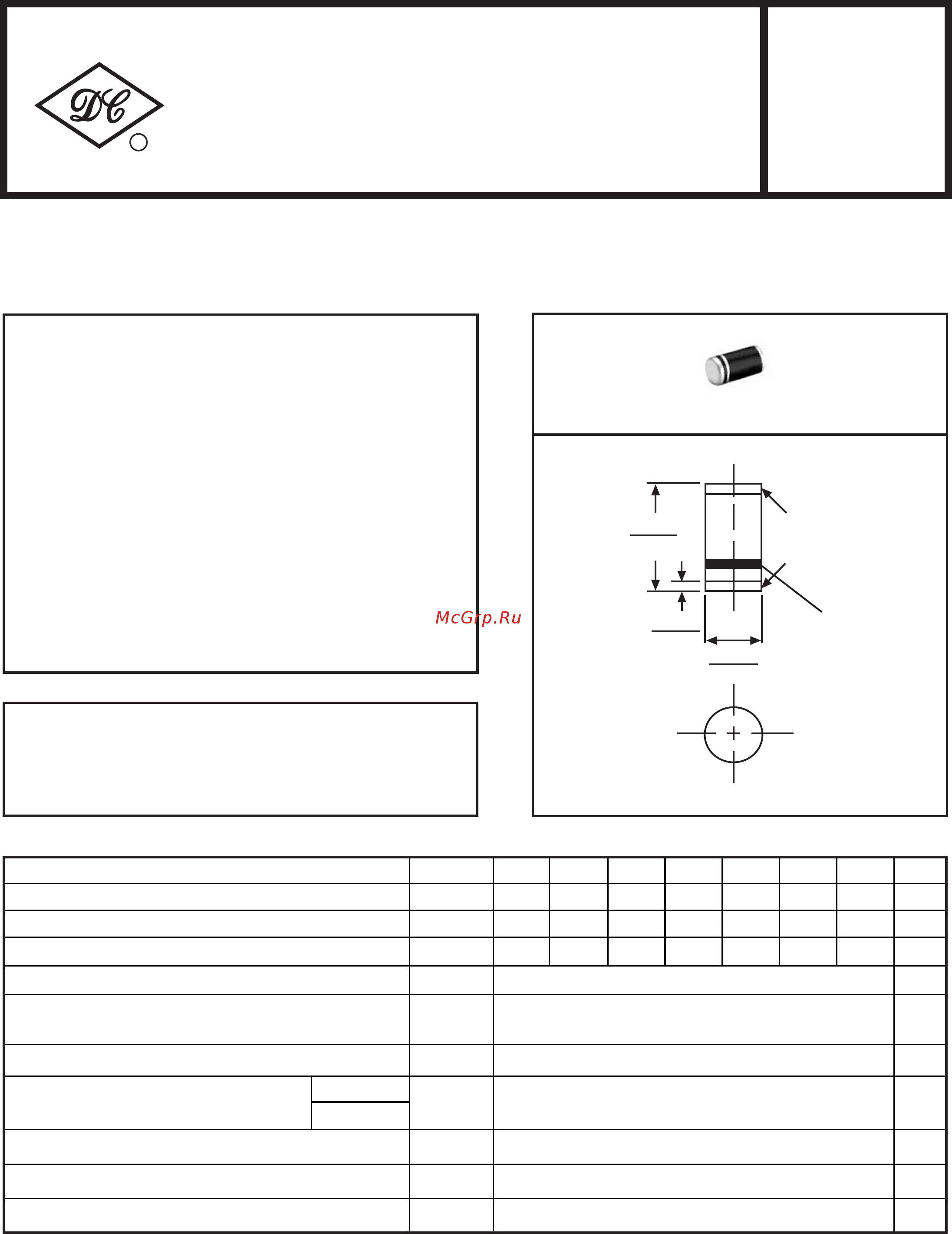
SM5391
THRU
SM5399
Dimensions in inches and (millimeters)
RECTIFIER SPECIALISTS
R
DC COMPONENTS CO., LTD.
Maximum Recurrent Peak Reverse Voltage
Maximum RMS Voltage
Maximum DC Blocking Voltage
Peak Forward Surge Current 8.3 ms single half sine-wave
superimposed on rated load (JEDEC Method)
Operating and Storage Temperature Range
Typical Thermal Resistance
(Note 2)
Maximum DC Reverse Current at Rated
DC Blocking Voltage
Maximum Instantaneous Forward Voltage at 1.5A DC
SM5391 SM5392 SM5393 SM5395 SM5397 SM5398 SM5399
Typical Junction Capacitance (Note
1
)
Maximum Average Forward Rectified Current
at T
A
= 75
o
C
MAXIMUM RATINGS AND ELECTRICAL CHARACTERISTICS
Ratings at 25 C ambient temperature unless otherwise specified.
Single phase, half wave, 60Hz, resistive or inductive load.
For capacitive load, derate current by 20%.
@ TA=25
o
C
@ TA=100
o
C
35
50
50
70
100
100
140
200
200
280
400
400
420
600
600
560
800
800
700
1000
1000
1.5
50
-55 to +150
6
0
1.1
5.0
15
100
T
J
,T
STG
Rθ
JA
C
J
I
R
SYMBOL
V
RRM
V
DC
I
O
I
FSM
V
RMS
V
F
SM-1(DO-213AB)
.024(0.6)
.016(0.4)
SOLDERABLE
ENDS
CATHODE MARK
.205(5.2)
.190(4.8)
.106(2.7)
.095(2.4)
Volts
Amps
UNITS
µAmps
o
C/W
pF
o
C
Volts
Volts
Amps
Volts
REV-3,MAY,2017 www.dccomponents.com1
o
Note 1: Measured at 1 MHz and applied reverse voltage of 4.0 volts.
Note 2: Typical thermal resistance from junction ambient.
* Ideal for surface mounted applications
* Glass passivated junction
* Low leakage current
* Low profile package
* Fast switching
FEATURES
MECHANICAL DATA
*Case: Molded plastic
* Epoxy: UL 94V-0 rated flame retardant
*Lead: MIL-STD-202E, Method 208 guaranteed
*Polarity: Color band denotes cathode end
* Mounting position: Any
*Weight: 0.12 gram approx.
TECHNICAL SPECIFICATIONS OF GENERAL PURPOSE SILICON RECTIFIER
VOLTAGE RANGE - 50 to 1000 Volts CURRENT - 1.5 Amperes
Содержание
Похожие устройства
- Zota Pony 15 Монтажные размеры
- Zota Pony 15 Инструкция по эксплуатации
- DC COMPONENTS SM5392-DC Инструкция по эксплуатации
- DC COMPONENTS SM5393-DC Инструкция по эксплуатации
- Zota Pony 25 Монтажные размеры
- Zota Pony 25 Инструкция по эксплуатации
- DC COMPONENTS SM5395-DC Инструкция по эксплуатации
- Sennheiser PC 2 CHAT Краткая инструкция
- DC COMPONENTS SM5397-DC Инструкция по эксплуатации
- DC COMPONENTS SM5398-DC Инструкция по эксплуатации
- DC COMPONENTS SM5399-DC Инструкция по эксплуатации
- DC COMPONENTS SM5400-DC Инструкция по эксплуатации
- Sennheiser PC 5 CHAT Краткая инструкция
- DC COMPONENTS SM5401-DC Инструкция по эксплуатации
- DC COMPONENTS SM5402-DC Инструкция по эксплуатации
- DC COMPONENTS SM5404-DC Инструкция по эксплуатации
- DC COMPONENTS SM5406-DC Инструкция по эксплуатации
- DC COMPONENTS SM5407-DC Инструкция по эксплуатации
- DC COMPONENTS SM5408-DC Инструкция по эксплуатации
- Sennheiser IE 4 Инструкция