
DC COMPONENTS SR540 Инструкция по эксплуатации онлайн
* Lead: MIL-STD-202E, Method 208 guaranteed
* Polarity: Color band denotes cathode end
@T
A
= 25
o
C
@T
A
= 100
o
C
50
400
Typical Thermal Resistance (Note 1)
18
0
C/W
R
JA
θ
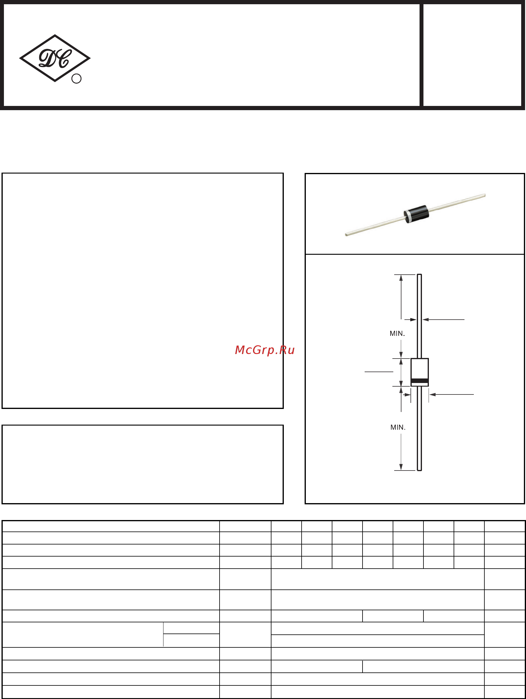
.052(1.3)
.048(1.2)
.220(5.6)
.197(5.0)
DIA.
DIA.
1.0(25.4)
.375(9.5)
.335(8.5)
1.0(25.4)
FEATURES
* High reliability
* Low switching noise
* Low forward voltage drop
* High current capability
* High switching capability
MECHANICAL DATA
MAXIMUM RATINGS AND ELECTRICAL CHARACTERISTICS
Ratings at 25
o
C ambient temperature unless otherwise specified.
Single phase, half wave, 60 Hz, resistive or inductive load.
For capacitive load, derate current by 20%.
* Case: Molded plastic
* Epoxy: UL 94V-0 rate flame retardant
* Mounting position: Any
* Weight: 1.18 grams
SR520
THRU
SR5100
NOTES : 1. Thermal Resistance (Junction to Ambient): Vertical PC Board Mounting, 0.5*(12.7mm) Lead Length.
2. Measured at 1 MHz and applied reverse voltage of 4.0 volts.
DO-27
Dimensions in inches and (millimeters)
Maximum DC Reverse Current
at Rated DC Blocking Voltage
V
F
I
R
mAmps
Maximum Instantaneous Forward Voltage at 5.0A DC Volts
2.0
Maximum Recurrent Peak Reverse Voltage
Maximum RMS Voltage
Maximum DC Blocking Voltage
Maximum Average Forward Rectified Current
.375*(9.5mm) lead length
Peak Forward Surge Current 8.3 ms single half sine-wave
superimposed on rated load (JEDEC Method)
Typical Junction Capacitance (Note 2)
SYMBOL
V
RRM
V
DC
I
FSM
C
J
T
STG
V
RMS
UNITS
Volts
Volts
Volts
Amps5.0
150
550
Amps
0
C
Storage Temperature Range
I
O
pF
Operating Temperature Range
T
J
-65 to +150
-65 to +150
0
C
RECTIFIER SPECIALISTS
R
DC COMPONENTS CO., LTD.
.55
.70 .85
SR520 SR530 SR540 SR550 SR560 SR580 SR5100
20 30 40 50 60 80 100
14 21 28 35 42 56 70
20 30 40 50 60 80 100
TECHNICAL SPECIFICATIONS OF
SCHOTTKY BARRIER RECTIFIER
VOLTAGE RANGE - 20 to 100 Volts CURRENT - 5.0 Amperes
REV-1,Apr/25/2013
Содержание
- 1 48 1 1
- 5 97 5 dia 1
- 9 35 8 1
- C ambient temperature unless otherwise specified 1
- Case molded plastic epoxy ul 94v 0 rate flame retardant 1
- Dc components co ltd 1
- For capacitive load derate current by 20 1
- High reliability low switching noise low forward voltage drop high current capability high switching capability 1
- Lead mil std 202e method 208 guaranteed polarity color band denotes cathode end 1
- Maximum ratings and electrical characteristics 1
- Mechanical data 1
- Mounting position any weight 1 8 grams 1
- Ratings at 25 1
- Rectifier specialists 1
- Rev 1 apr 25 2013 1
- Single phase half wave 60 hz resistive or inductive load 1
- Sr5100 1
- Dc components co ltd 2
- Rating and characteristic curves sr520 thru sr5100 2
Похожие устройства
- DC COMPONENTS SR550 Инструкция по эксплуатации
- DC COMPONENTS SR2100 Инструкция по эксплуатации
- DC COMPONENTS SR240 Инструкция по эксплуатации
- DC COMPONENTS SR250 Инструкция по эксплуатации
- DC COMPONENTS SR260 Инструкция по эксплуатации
- DC COMPONENTS BZX84C10-DC Инструкция по эксплуатации
- Hiberg VB 6040 GY Инструкция по эксплуатации
- DC COMPONENTS BZX84C11-DC Инструкция по эксплуатации
- DC COMPONENTS BZX84C12-DC Инструкция по эксплуатации
- DC COMPONENTS BZX84C13-DC Инструкция по эксплуатации
- DC COMPONENTS BZX84C15-DC Инструкция по эксплуатации
- DC COMPONENTS BZX84C16-DC Инструкция по эксплуатации
- DC COMPONENTS BZX84C18-DC Инструкция по эксплуатации
- DC COMPONENTS BZX84C20-DC Инструкция по эксплуатации
- DC COMPONENTS BZX84C22-DC Инструкция по эксплуатации
- DC COMPONENTS BZX84C24-DC Инструкция по эксплуатации
- DC COMPONENTS BZX84C27-DC Инструкция по эксплуатации
- DC COMPONENTS BZX84C2V4-DC Инструкция по эксплуатации
- Akvilon AT-9 Инструкция
- DC COMPONENTS BZX84C2V7-DC Инструкция по эксплуатации