
GW INSTEK GDM-357 Расширенная инструкция онлайн
Содержание
Похожие устройства
- GW INSTEK GDM-360 Инструкция по эксплуатации
- GW INSTEK GDM-360 Расширенная инструкция
- GW INSTEK GDM-360 Технические характеристики
- GW INSTEK GDM-397 Инструкция по эксплуатации
- GW INSTEK GDM-397 Расширенная инструкция
- GW INSTEK GDM-397 Технические характеристики
- GW INSTEK GDM-398 Инструкция по эксплуатации
- GW INSTEK GDM-398 Расширенная инструкция
- GW INSTEK GDM-398 Технические характеристики
- GW INSTEK GDM-452 Инструкция по эксплуатации
- GW INSTEK GDM-452 Технические характеристики
- GW INSTEK GDM-452 Расширенная инструкция
- GW INSTEK GDM-461 Инструкция по эксплуатации
- GW INSTEK GDM-461 Расширенная инструкция
- GW INSTEK GDM-461 Технические характеристики
- METRIX MTX202 Инструкция по эксплуатации
- METRIX MTX202 Технические характеристики
- METRIX MTX202 Расширенная инструкция
- METRIX MTX 203 Инструкция по эксплуатации
- METRIX MTX 203 Технические характеристики
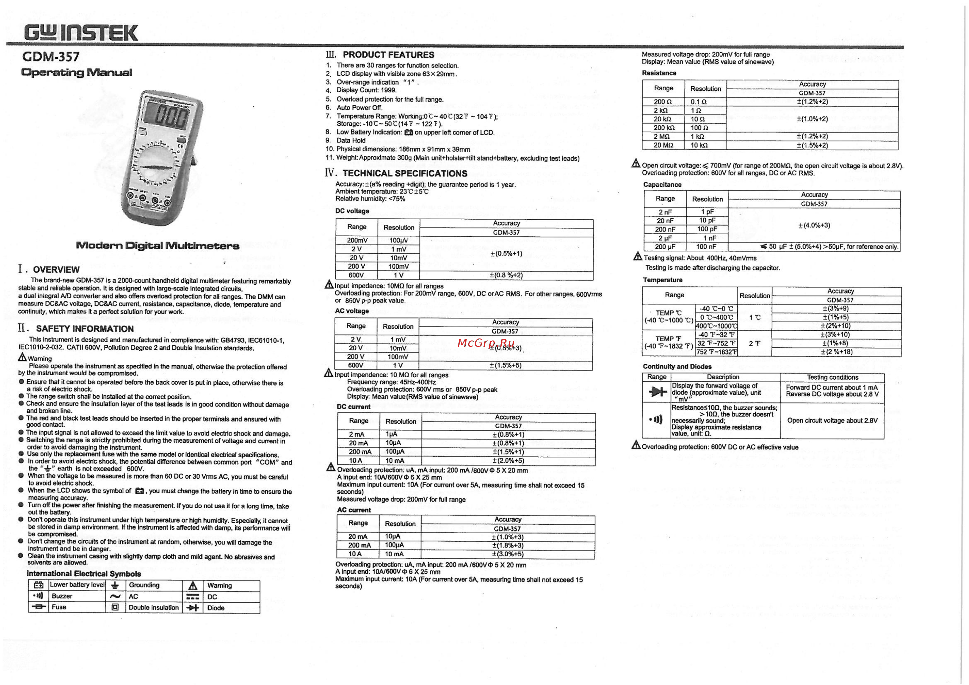
GWIDSTEK ID PRODUCT FEATURES GDM 357 1 There are 30 ranges for function selection 2 LCD display with visible zone 63 x 29mm 3 Over range indication 1 4 Display Count 1999 5 Overload protection for fhe full range 6 Auto Power Off 7 Temperature Range Workmg 0 C 40C 32T 104T Storage 10 C 50 C 14 122 T 8 Low Battery Indication 3 on upper left comer of LCD 9 Data Hold 10 Physical dimensions 186mm x 91mm x 39mm 11 Weight Approximate 300g Main unit holster tilt stand battery excluding test leads Operating Manual Accuracy a reading digit the guarantee period is 1 year Ambient temperature 23 C 5 C Relative humidity 75 DC voltage Modern Digital Multimeters I OVERVIEW The brand new GDM 357 is a 2000 count handheld digital multimeter featuring remarkably stable and reliable operation It is designed with large scale integrated circuits e dual integral A D converter and also offers overload protection for all ranges The DMM can measure DC AC voltage DC AC current resistance capacitance diode temperature and continuity which makes it a perfect solution for your work Resolution 200mV 2V 20 V 200 V 600V 100pV 1 mV 10mV 100mV 1V Range Resolution 2V 20 V 200 V 600V 1 mV 10mV 100mV 1V Ensure that it cannot be operated before the back cover is put in place otherwise there is a nsk of electric shock The range switch shall be installed at the correct position Check and ensure the insulation layer of the test leads is in good condition without damage and broken line The red and black test leads should be inserted in the proper terminals and ensured with good contact The input signal is not allowed to exceed the limit value to avoid electric shock and damage Switching the range is strictly prohibited during the measurement of voltage and current in order to avoid damaging the instrument Use only the replacement fuse with the same model or identical electrical specifications In order to avoid electric shock the potential difference between common port COM and the 4r earth is not exceeded 600V When the voltage to be measured Is more than 60 DC or 30 Vims AC you must be careful to avoid electric shock When the LCD shows the symbol of 3 you must change the battery in time to ensure the measuring accuracy Turn off the power after finishing the measurement If you do not use it for a long time take out the battery Don t operate this instrument under high temperature or high humidity Especially it cannot be tored in damp environment If the instrument is affected with damp its performance will be compromised Don t change the circuits of the instrument at random otherwise you will damage the instrument and be in danger Clean the instrument casing with slightly damp doth and mild agent No abrasives and solvents are allowed International Electrical Symbols Lower battery leve Buzzer B Fuse A Warning AC Double insulation H Diode Grounding 0 DC Accuracy GDM 357 0 5 1 Resolution 200 2 Idi 20 kQ 200 kQ 2 MQ 20 MQ 0 1 Cl 1 Cl 10Q 100 Ci 1 kii 10 k 2 Accuracy Range Resolution 2 nF 20 nF 200 nF 2 pF 200 pF 1pF 10 pF 100 pF Resolution 1pA 10pA 100pA 10mA 0 8 3 Accuracy GDM 357 0 8 1 0 8 1 1 5 1 2 0 5 Overloading protection uA mA input 200 mA 600V 4 5 X 20 mm A Input end 10A 60OV 6 X 25 mm Maximum input current 10A For current over 5A measuring time shall not exceed 15 seconds Measured voltage drop 200mV for full range AC current Range Resolution 20 mA 200 mA 10A 10pA 100pA 10 mA 1 0 2 1 2 2 1 5 2 Accuracy GDM 357 4 0 3 1 nF 100 nF 50 pF 5 0 4 50pF for reference only Tesing signal About 400Hz 40mVrms Temperature Range TEMP C 40 C 1000 C TEMPT 40 T 1832 T Accuracy GDM 357 1 0 3 1 8 3 3 0 5 Overloading protection uA mA input 200 mA 600V t 5 X 20 mm A input end 10A 600V b 6 X 25 mm Maximum input current 10A For current over 5A measuring time shall not exceed 15 seconds Accuracy Resolution 40 C O C 0 V 400 C GDM 357 3 9 1 5 2 10 3 10 1 8 2 18 1 c koo c ioooc 40T 32T 32 T 752 T 752T 1832T 2T Continuity and Diodes Range DC current 2 mA 20 mA 200 mA 10A GDM 357 1 2 2 Capacitance GDM 357 1 5 5 2Ù Input impendence 10 MQ for all ranges Frequency range 45Hz 400Hz Overloading protection 600V rms or 850V p p peak Display Mean value RMS value of sinewave Range Accuracy Testing is made after discharging the capacitor 0 8 2 AC voltage This instrument is designed and manufactured in compliance with GB4793 IEC61Q10 1 IEC1010 2 032 CATH 600V Pollution Degree 2 and Double Insulation standards Please operate the instrument as specified in the manual otherwise the protection offered by the instrument would be compromised Range Input impedance 10MQforall ranges Overloading protection For 200mV range 600V DC or AC RMS For other ranges 600Vrms or 850V p p peak value II SAFETY INFORMATION A Warning Resistance A Open circuit voltage 700mV for range of 200MQ the open circuit voltage is about 2 8V Overloading protection 600V for all ranges DC or AC RMS IV TECHNICAL SPECIFICATIONS Range Measured voltage drop 200mV for full range Display Mean value RMS value of sinewave Description Display the forward voltage of diode approximate value unit mV Resistances 0D the buzzer sounds 10Q the buzzer doesn t necessarily sound Display approximate resistance value unit O Testing conditions Forward DC cuirent about 1 mA Reverse DC voltage about 2 8 V Open circuit voltage about 2 8V A Overloading protection 600V DC or AC effective value