
Uni-T UT33C+ Расширенная инструкция онлайн
Содержание
- P n 110401106545x 1
- Palm size multimeter 1
- User manual 1
- Ut33a b c o 1
- Continuity diode 2
- Headquarters uni trend group limited rm901 9 f nanyang plaza 57 hung to road kwun tong kowloon hong kong tel 852 2950 9168 fax 852 2950 9303 http www u n trend com 2
- Ix technical specification 2
- Manufacturer uni trend technology china limited no 6 gong ye bei 1 st road songshan lake national high tech industrial development zone dongguan city guangdong province china postal code 523 808 2
- X maintenance 2
Похожие устройства
- Uni-T UT33D+ Инструкция по эксплуатации
- Uni-T UT33D+ Инструкция язык en
- Uni-T UT33D+ Расширенная инструкция
- Uni-T UT39B Инструкция по эксплуатации
- Uni-T UT39B Расширенная инструкция
- Uni-T UT39B Инструкция язык en
- Uni-T UT39A Инструкция по эксплуатации
- Uni-T UT39A Расширенная инструкция
- Uni-T UT39A Инструкция язык en
- Uni-T UT39C Инструкция по эксплуатации
- Uni-T UT39C Расширенная инструкция
- Uni-T UT39C Инструкция язык en
- Uni-T UT50A Инструкция по эксплуатации
- Uni-T UT50A Расширенная инструкция
- Uni-T UT50A Инструкция язык en
- Uni-T UT50B Инструкция по эксплуатации
- Uni-T UT50B Расширенная инструкция
- Uni-T UT50B Инструкция язык en
- Uni-T UT50C Инструкция по эксплуатации
- Uni-T UT50C Расширенная инструкция
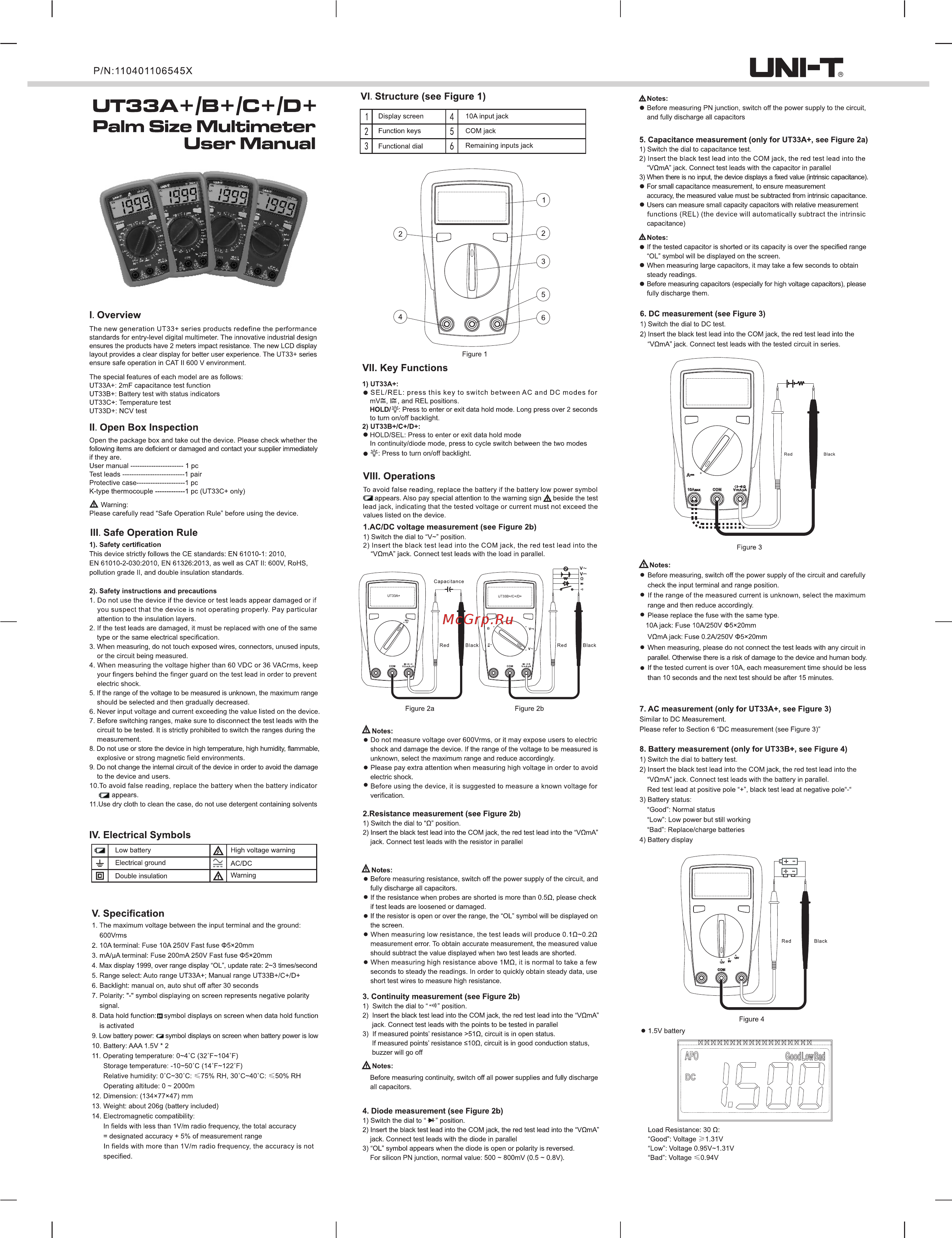
UNI T P N 110401106545X UT33A B C O Palm Size Multimeter User Manual VI Structure see Figure 1 1 2 3 Display screen Function keys Functional dial 4 5 6 Notes Before measuring PN junction switch off the power supply to the circuit and fully discharge all capacitors 10A input jack COM jack Remaining inputs jack 5 Capacitance measurement only for UT33A see Figure 2a 1 Switch the dial to capacitance test 2 Insert the black test lead into the COM jack the red test lead into the VOmA jack Connect test leads with the capacitor in parallel 3 When there is no input the device displays a fixed value intrinsic capacitance For small capacitance measurement to ensure measurement accuracy the measured value must be subtracted from intrinsic capacitance Users can measure small capacity capacitors with relative measurement functions REL the device will automatically subtract the intrinsic capacitance Notes If the tested capacitor is shorted or its capacity is over the specified range OL symbol will be displayed on the screen When measuring large capacitors it may take a few seconds to obtain steady readings Before measuring capacitors especially for high voltage capacitors please fully discharge them I Overview 6 DC measurement see Figure 3 The new generation UT33 series products redefine the performance standards for entry level digital multimeter The innovative industrial design ensures the products have 2 meters impact resistance The new LCD display layout provides a clear display for better user experience The UT33 series ensure safe operation in CAT II 600 V environment The special features of each model are as follows UT33A 2mF capacitance test function UT33B Battery test with status indicators UT33C Temperature test UT33D NCV test II Open Box Inspection Open the package box and take out the device Please check whether the following items are deficient or damaged and contact your supplier immediately if they are User manual 1pc Test leads 1pair Protective case 1pc К type thermocouple 1 pc UT33C only A Warning Please carefully read Safe Operation Rule before using the device III Safe Operation Rule 1 Safety certification This device strictly follows the CE standards EN 61010 1 2010 EN 61010 2 030 2010 EN 61326 2013 as well as CAT II 600V RoHS pollution grade 11 and double insulation standards 2 Safety instructions and precautions 1 Do not use the device if the device or test leads appear damaged or if you suspect that the device is not operating properly Pay particular attention to the insulation layers 2 If the test leads are damaged it must be replaced with one of the same type or the same electrical specification 3 When measuring do not touch exposed wires connectors unused inputs or the circuit being measured 4 When measuring the voltage higher than 60 VDC or 36 VACrms keep your fingers behind the finger guard on the test lead in order to prevent electric shock 5 If the range of the voltage to be measured is unknown the maximum range should be selected and then gradually decreased 6 Never input voltage and current exceeding the value listed on the device 7 Before switching ranges make sure to disconnect the test leads with the circuit to be tested It is strictly prohibited to switch the ranges during the measurement 8 Do not use or store the device in high temperature high humidity flammable explosive or strong magnetic field environments 9 Do not change the internal circuit of the device in order to avoid the damage to the device and users 10 To avoid false reading replace the battery when the battery indicator 3 appears 11 Use dry cloth to clean the case do not use detergent containing solvents 1 Switch the dial to DC test 2 Insert the black test lead into the COM jack the red test lead into the VQmA jack Connect test leads with the tested circuit in series Figure 1 VII Key Functions 1 UT33A SEL REL press this key to switch between AC and DC modes for mV IS and REL positions HOLD Press to enter or exit data hold mode Long press over 2 seconds to turn on off backlight 2 UT33B C D HOLD SEL Press to enter or exit data hold mode In continuity diode mode press to cycle switch between the two modes g Press to turn on off backlight VIII Operations To avoid false reading replace the battery if the battery low power symbol O appears Also pay special attention to the warning sign A beside the test lead jack indicating that the tested voltage or current must not exceed the values listed on the device 1 AC DC voltage measurement see Figure 2b 1 Switch the dial to V position 2 Insert the black test lead into the COM jack the red test lead into the V mA jack Connect test leads with the load in parallel Before measuring switch off the power supply of the circuit and carefully check the input terminal and range position If the range of the measured current is unknown select the maximum range and then reduce accordingly Please replace the fuse with the same type lOAjack Fuse 10A 250V t 5 20mm VQmAjack Fuse 0 2A 250V t 5 20mm When measuring please do not connect the test leads with any circuit in parallel Otherwise there is a risk of damage to the device and human body If the tested current is over 10A each measurement time should be less than 10 seconds and the next test should be after 15 minutes Figure 2a Figure 2b Q Low battery A High voltage warning 4 Electrical ground AC DC 0 Double insulation A Warning V Specification 1 The maximum voltage between the input terminal and the ground 600Vrms 2 10A terminal Fuse 10A250V Fast fuse 5 20mm 3 mA pA terminal Fuse 200mA 250V Fast fuse 5 20mm 4 Max display 1999 over range display OL update rate 2 3 times second 5 Range select Auto range UT33A Manual range UT33B C D 6 Backlight manual on auto shut off after 30 seconds 7 Polarity symbol displaying on screen represents negative polarity signal 8 Data hold function Cl symbol displays on screen when data hold function is activated 9 Low battery power a symbol displays on screen when battery power is low 10 Battery AAA 1 5V 2 11 Operating temperature 0 4 C 32T 104T Storage temperature 10 50 C 14 F 122 F Relative humidity 0 C 30 C i75 RH 3O C 4O C 50 RH Operating altitude 0 2000m 7 AC measurement only for UT33A see Figure 3 Similar to DC Measurement A Notes Do not measure voltage over 600Vrms or it may expose users to electric shock and damage the device If the range of the voltage to be measured is unknown select the maximum range and reduce accordingly Please pay extra attention when measuring high voltage in order to avoid electric shock Before using the device it is suggested to measure a known voltage for verification 2 Resistance measurement see Figure 2b 1 Switch the dial to Q position 2 Insert the black test lead into the COM jack the red test lead into the VQmA jack Connect test leads with the resistor in parallel IV Electrical Symbols Figure 3 Notes Please refer to Section 6 DC measurement see Figure 3 8 Battery measurement only for UT33B see Figure 4 1 Switch the dial to battery test 2 Insert the black test lead into the COM jack the red test lead into the VOmA jack Connect test leads with the battery in parallel Red test lead at positive poleblack test lead at negative pole 3 Battery status Good Normal status Low Low power but still working Bad Replace charge batteries 4 Battery display A Notes Before measuring resistance switch off the power supply of the circuit and fully discharge all capacitors If the resistance when probes are shorted is more than 0 5D please check if test leads are loosened or damaged If the resistor is open or over the range the OL symbol will be displayed on the screen When measuring low resistance the test leads will produce 0 1Q 0 2Q measurement error To obtain accurate measurement the measured value should subtract the value displayed when two test leads are shorted When measuring high resistance above 1MQ it is normal to take a few seconds to steady the readings In order to quickly obtain steady data use short test wires to measure high resistance 3 Continuity measurement see Figure 2b 1 Switch the dial to W position 2 Insert the black test lead into the COM jack the red test lead into the VOmA jack Connect test leads with the points to be tested in parallel 3 If measured points resistance 510 circuit is in open status If measured points resistance 21OQ circuit is in good conduction status buzzer will go off Figure 4 1 5V battery A Notes Before measuring continuity switch off all power supplies and fully discharge all capacitors 12 Dimension 134 77 47 mm 13 Weight about 206g battery included 14 Electromagnetic compatibility In fields with less than 1 V m radio frequency the total accuracy designated accuracy 5 of measurement range In fields with more than 1 V m radio frequency the accuracy is not specified 4 Diode measurement see Figure 2b 1 Switch the dial to X position 2 Insert the black test lead into the COM jack the red test lead into the VOmA jack Connect test leads with the diode in parallel 3 OL symbol appears when the diode is open or polarity is reversed For silicon PN junction normal value 500 800mV 0 5 0 8V Load Resistance 30 Q Good Voltage 1 31V Low Voltage 0 95V 1 31V Bad Voltage S 0 94V