
Gigabyte Setto 1020 Инструкция онлайн
Содержание
Похожие устройства
- Gigabyte GZ-X7 Инструкция
- Daikin EWYT300B-SSA2-VFDFAN Инструкция по эксплуатации
- Daikin EWYT300B-SSA2-VFDFAN Инструкция по монтажу
- Daikin EWYT300B-SSA2-VFDFAN Технические данные
- Gigabyte GZ-X8 Инструкция
- Daikin EWYT340B-SSA2 Технические данные
- Daikin EWYT340B-SSA2 Инструкция по эксплуатации
- Daikin EWYT340B-SSA2 Инструкция по монтажу
- Daikin EWYT340B-SSA2-VFDFAN Технические данные
- Daikin EWYT340B-SSA2-VFDFAN Инструкция по эксплуатации
- Daikin EWYT340B-SSA2-VFDFAN Инструкция по монтажу
- Daikin EWYT390B-SSA2 Инструкция по эксплуатации
- Daikin EWYT390B-SSA2 Инструкция по монтажу
- Daikin EWYT390B-SSA2 Технические данные
- Daikin EWYT390B-SSA2-VFDFAN Инструкция по эксплуатации
- Daikin EWYT390B-SSA2-VFDFAN Технические данные
- Daikin EWYT390B-SSA2-VFDFAN Инструкция по монтажу
- Daikin EWYT430B-SSA2 Инструкция по эксплуатации
- Daikin EWYT430B-SSA2 Технические данные
- Daikin EWYT430B-SSA2 Инструкция по монтажу
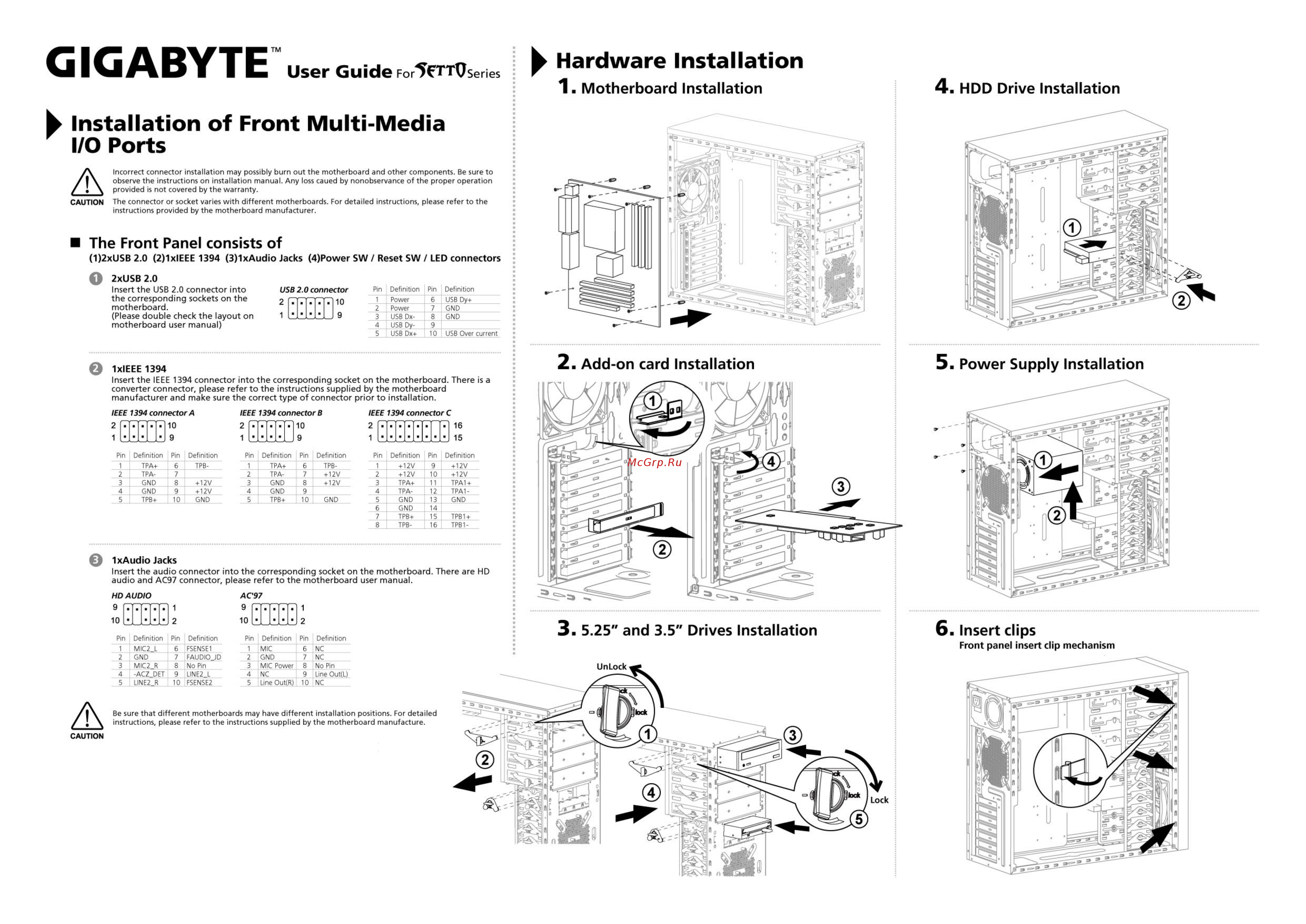
GIGABYTE User Guide For5fTTVseries Hardware Installation 1 Motherboard Installation 4 HDD Drive Installation k Installation of Front Multi Media I O Ports Incorrect connector installation may possibly burn out the motherboard and other components Be sure to observe the instructions on installation manual Any loss caued by nonobservance of the proper operation provided is not covered by the warranty CAUTION The connector or socket varies with different motherboards For detailed instructions please refer to the instructions provided by the motherboard manufacturer The Front Panel consists of 1 2xUSB 2 0 2 1xlEEE 1394 3 1xAudio Jacks 4 Power SW Reset SW LED connectors O 2xUSB 2 0 Insert the USB 2 0 connector into the corresponding sockets on the motherboard Please double check the layout on motherboard user manual e USB 2 0 connector Pin Definition Pin Definition 2 10 1 9 1 2 3 4 5 Power Power USB DxUSB DyUSB Dx 6 7 8 9 10 USB Pvt CAD CAD USB Over current 5 Power Supply Installation IxlEEE 1394 Insert the IEEE 1394 connector into the corresponding socket on the motherboard There is a converter connector please refer to the instructions supplied by the motherboard manufacturer and make sure the correct type of connector prior to installation IEEE 1394 connector A IEEE 1394 connector B IEEE 1394 connector C 2 rrmr io 2l l 10 2 l l I l 16 i LLL 9 1LL 9 1 LL I I is Pin Definition Pin Definition 1 TPA 6 TPB2 TPA 7 3 GND 8 4 GND 9 5 TPB 10 GND 12V 12V Pin Definition Pin Definition 1 TPA 6 TPB2 TPA 7 3 GND 8 4 GND 9 5 TPB 10 GND 12V 12V Pin Definition Pin Definition 1 12V 9 2 12V 10 3 TPA 11 TPA1 4 TPA 12 TPA15 GND 13 GND 6 GND 14 7 1 TPB 1 15 I TPB1 8 TPB 16 TPB1 12V 12V IxAudio Jacks Insert the audio connector into the corresponding socket on the motherboard There are HD audio and AC97 connector please refer to the motherboard user manual HD AUDIO AC97 9 TTT7T 9 fT Pin 1 2 3 4 5 Definition Pin MIC2_L 6 GND 7 8 MIC2 R ACZ_DET 9 10 LINE2_R Definition FSENSE1 FAUDIO_JD No Pin LINE2 L FSENSE2 Pin Definition Pin Definition 1 2 3 4 5 MIC GND MIC Power NC line Out R 6 7 8 9 10 NC NC No Pin Line Out L NC Be sure that different motherboards may have different installation positions instructions please refer to the instructions supplied by the motherboard manufacture 6 Insert clips Front panel insert clip mechanism For detailed