
Zkteco TF1700 Руководство по установке онлайн
Version: 1.1 Date: Sep. 2011
TF1700 Installation Guide
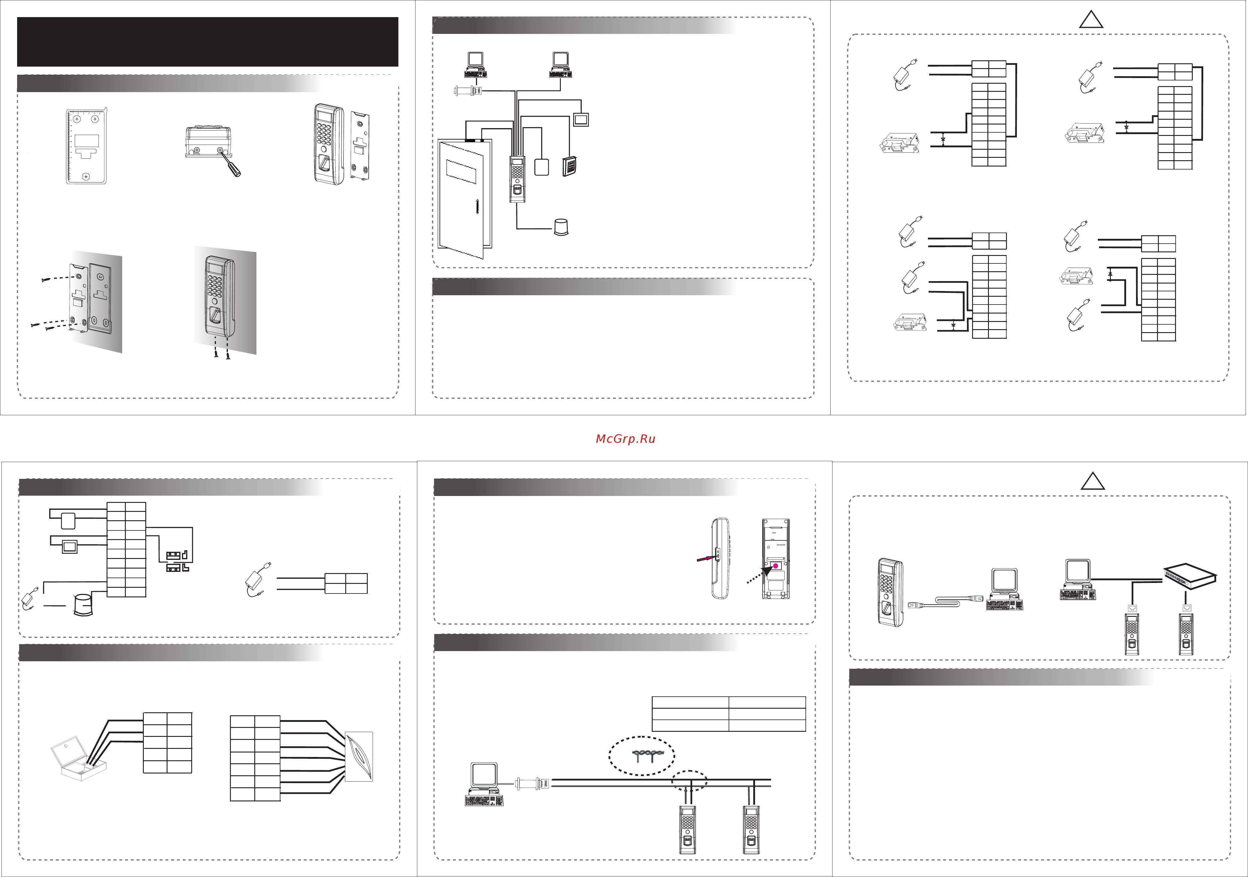
1.Equipment Installation
!
2.Structure and Function
3.Lock Connection
2 3
Wiri ng Hole
Instru ctio n for the Mo unti ng Paper
Before t he dev ice is fas tene d, pleas e
stick th e pape r to the pla ce whe re you
want to in stal l it, then m ake ho les and
lay cabl es acc ording t o the mo unting
paper.
TF1 700 Mou nting P aper
(on ly for yo ur refe rence )
Fixi ng Hole
Fixi ng Hole
Fixi ng Hole
10
11
12
13
(1) Post the mounting template on the
wall.Drill the holes according to
the marks on the template (holes
(2) Remove the screws on the
(3) Take away the back plate.
(5) Tighten the screws on the bottom,
plate on the wall according to the
(4) Fix the plastic pad and the back
for screws and wiring).
bottom of device.
2. Structure and Function
fix the device to the back plate.
mounting paper.
RS485
TCP/IP
Lock
Sensor
①
③
Alarm
RS485 Converter
②
Exit Button
⑤
External Reader
④
Door Bell
%
BUTT ON
EXIT
⑦
⑥
Access Control System Function
(1) If a registered user verified, the device will export the
signal to unlock the door.
(3) If only the d llegal removed, the deviceevice being i ly
(4) is External card reader supported.
(5) is it is External exit button supported, convenient to
(1) The system supports NO lock and NC lock. For example the NO lock (normally open at power
(2) When the electrical lock is connected to the Access Control System, you need to parallel one FR107
(2) Door sensor will detect the on-off state If the door is
unexpected opened or improperly closed, the alarm signal
(digital value) will be triggered.
will export alarm signal.
open the door inside.
(7) Supports , modes with RS485 TCP/IP to connect PC. One
PC can manage multiple devices.
(6) External door bell is supported.
NC LOCK
-
+
DC12V
+
NC LOCK
+
-
NO LOCK
-
-
FR 107
+
-
FR 107
-
+
DC12V
+
-
-
+
DC power
-
+
DC12V
-
+
DC power
+
-
FR 107
+
(1) Share power with the lock:
(2) Does not share power with the lock:
Device does not share power with the lock:
①: ‘‘I’: device output current, ‘ ’: lock voltage, ’: lock current.ULOCK ILOCK
Device share power with the lock:
U =12V, I-ILOCK 1A And the distance between the lock and theLOCK > …… device is ≤10 meters.①;
A. U =12V, I-ILOCK 1A he distance between the lock and theLOCK ≤ ; B. ULOCK≠12V; C. T device is >10 meters.
Warning: No operating with power on
on) is connected with "NO" and "COM" terminals, and the NC lock is connected with
diode (equipped in the package) to prevent the self-inductance EMF affect the system,
"NC" and "COM" terminals.
do not reverse the polarities.
1
4.Other Connection
5.Power Connection
!
6
5
4
+
Door Bell
%
EXIT
BUTT ON
Alarm Power
Exit Button
Door Sensor
5. Power Connection:
Input DC 12V, 500mA (50mA standby)
Positive is connected with ‘+12V’, negative is connected
with ’GND’ (do not reverse the polarities).
DC12V
-
-
+
Alarm
Alarm Voltage output ≤ DC 12V
Warning: No operating with power on
GND
+12V
Access Control Panel
6. Wiegand Output
The device supports standard Wiegand 26
output, so you can connect it with most of the
7. Wiegand Input
supports to connect with card reader.an independent
The device has the function of Wiegand input signal . It
They are installed each side of the door, to control the
access control devices by now.
DATA0
GND
DATA1
DATA1
DATA0
GLED
RLED
BEEP
(Please use Wiegand signal extender in long distance or interference environment).
(2) To keep the stability of Wiegand signal, connect the device and the access control or card reader in same
(1) Please keep the distance between the device and Access Control or Card Reader less than 90 meters
‘GND’ in any case.
8.Other Functions
Side View Back View
Tamper Magnet
Reset Button
(1) Manual Reset:
(2) Tamper Function:
other restart it.abnormality, you can use ‘Reset’ function to
button hole with than 2mm).a sharp tool (the tip diameter less
Operation: Remove the black rubber cap, then stick the Reset
If the device does not work properly because of misoperation or
In device installation, user need to put the magnet between the device
and movedthe back plate. If the device being illegally , and the magnet
being away from the device, it will trigger the alarm.
485+ RS485+
There are two modes that the PC software communicate and exchange information with the device:
RS485 and TCP/IP, and supports remote control.
9. Communication
(1) RS485 Mode:
Terminals PC Serial Ports
Please use specified RS485 wire, RS485 active converter
and bus-type wiring.
485- RS485-
Terminals definition please refers to the right table.
485+
485-
485+ 485-
RS485 Bus
485+ 485- 485+ 485-
RS485
Converter
IP Address:192.168.1.100
Subnet Mask:255.255.255.0
IP Address:192.168.1.124
Subnet Mask:255.255.255.0
(A)Crossover cable: The device and PC connected
(2) TCP/IP Mode:
Two ways for TCP/IP connection.
directly.
Switch
…
(B)Straight cable: The device and PC connected to
LAN/WAN through switch/Lanswitch.
10. Cautions:
(2)We recommend the 3DC A/12V power supply. Please contact our technical staff for details.
(5)Please connect the ‘GND’ before all the other wiring especially under the environment with much
( )3 Please read carefully the terminal description and wiring by rule strictly. Any damage
(4)Keep the exposed part of wire less than 5mm, to avoid unexpected connection.
(1)Power cable is connected after all the other wiring. If the device is working abnormally, please shut
caused by improper operations will be out of the range of our guarantee.
damage the device, and it is not included in the warranty.
(6)Do not change the cable type because of long distance between the power and the device.
down the power first, then make the necessary check. Kindly reminds you that any hot-plugging may
(7) Please use specified RS485 wire, RS485 active converter, and adopt bus-type wiring. If the communication
wire is longer than 100 meters, it is needed to parallel a terminal resistance on the last device of RS485 bus,
lock and access together.
and the value is about 120 ohm.
electrostatic.
GND
NO1
NO2
COM2
BELL+
BUT
COM1
SEN
NC1
BELL-
Purple
Brow n
Whi te
Red
Black
Yellow
Gray
Orange
Blue
Green
GND
+12V
Red
Black
GND
485+
WD1
WD0
485-
White
Black
Yellow
Blue
Green
IWD0
BEEP
GND
RLED
IWD1
GLED
+12V
Purple
White
Red
Black
Gray
Blue
Green
GND
NO1
NO2
COM2
BELL+
BUT
COM1
SEN
NC1
BELL-
Purpl e
Brown
Whi te
Red
Black
Yellow
Gray
Oran ge
Blue
Green
GND
+12V
Red
Black
GND
NO1
NO2
COM2
BELL+
BUT
COM1
SEN
NC1
BELL-
Purpl e
Brown
Whi te
Red
Black
Yellow
Gray
Oran ge
Blue
Green
GND
+12V
Red
Black
NO LOCK
-
+
DC12V
+
-
+
-
FR 107
GND
NO1
NO2
COM2
BELL+
BUT
COM1
SEN
NC1
BELL-
Purpl e
Brown
Whi te
Red
Black
Yellow
Gray
Oran ge
Blue
Green
GND
+12V
Red
Black
GND
NO1
NO2
COM2
BELL+
BUT
COM1
SEN
NC1
BELL-
Purpl e
Brown
Whi te
Red
Black
Yellow
Gray
Oran ge
Blue
Green
GND
+12V
Red
Black
Содержание
- 1 if a registered user verified the device will export the 1
- 1 share power with the lock 1
- 1 the system supports no lock and nc lock for example the no lock normally open at power 1
- 2 does not share power with the lock 1
- 2 door sensor will detect the on off state if the door is 1
- 2 when the electrical lock is connected to the access control system you need to parallel one fr107 1
- 3 if only the d llegal removed the device evice being i ly 1
- 4 is external card reader supported 1
- 5 is it is external exit button supported convenient to 1
- 6 do not change the cable type because of long distance between the power and the device 1
- 6 external door bell is supported 1
- 7 supports modes with rs485 tcp ip to connect pc one 1
- A crossover cable the device and pc connected 1
- Access control system function 1
- Button hole with than 2mm a sharp tool the tip diameter less 1
- Cautions 1
- Communication 1
- Device does not share power with the lock 1
- Diode equipped in the package to prevent the self inductance emf affect the system 1
- Do not reverse the polarities 1
- Down the power first then make the necessary check kindly reminds you that any hot plugging may 1
- Equipment installation 1
- Lock connection 1
- Nc and com terminals 1
- On is connected with no and com terminals and the nc lock is connected with 1
- Open the door inside 1
- Other connection 5 power connection 1
- Other functions 1
- Other restart it abnormality you can use reset function to 1
- Pc can manage multiple devices 1
- Please use wiegand signal extender in long distance or interference environment 1
- Rs485 and tcp ip and supports remote control 1
- Signal to unlock the door 1
- Structure and function 1
- Supports to connect with card reader an independent 1
- Tf1700 installation guide 1
- The device supports standard wiegand 26 1
- The marks on the template holes 1
- There are two modes that the pc software communicate and exchange information with the device 1
- Unexpected opened or improperly closed the alarm signal digital value will be triggered 1
- Version 1 date sep 2011 1
- Wall drill the holes according to 1
- Warning no operating with power on 1
- Wiegand input 1
- Wiegand output 1
- Will export alarm signal 1
- ① i device output current lock voltage lock current 1
Похожие устройства
- Zkteco X7 Техническое описание
- Zkteco X8-BT Техническое описание
- Zkteco X8s Руководство пользователя
- Zkteco X8s Техническое описание
- Zkteco MA300-BT Техническое описание
- MEAN WELL PLM-25-1050 Инструкция по эксплуатации
- MEAN WELL PLM-25-1050 Инструкция язык EN
- MEAN WELL PLM-25-1050 Datasheet
- MEAN WELL PLM-25-1050 Документация
- MEAN WELL PLM-25-350 Инструкция по эксплуатации
- MEAN WELL PLM-25-350 Инструкция язык EN
- MEAN WELL PLM-25-350 Datasheet
- MEAN WELL PLM-25-350 Документация
- MEAN WELL PLM-25-500 Инструкция по эксплуатации
- MEAN WELL PLM-25-500 Инструкция язык EN
- MEAN WELL PLM-25-500 Datasheet
- MEAN WELL PLM-25-500 Документация
- MEAN WELL PLM-25-700 Инструкция по эксплуатации
- MEAN WELL PLM-25-700 Инструкция язык EN
- MEAN WELL PLM-25-700 Datasheet