
Daikin FLKS50BVMB Сервис мануал онлайн
Inverter Pair
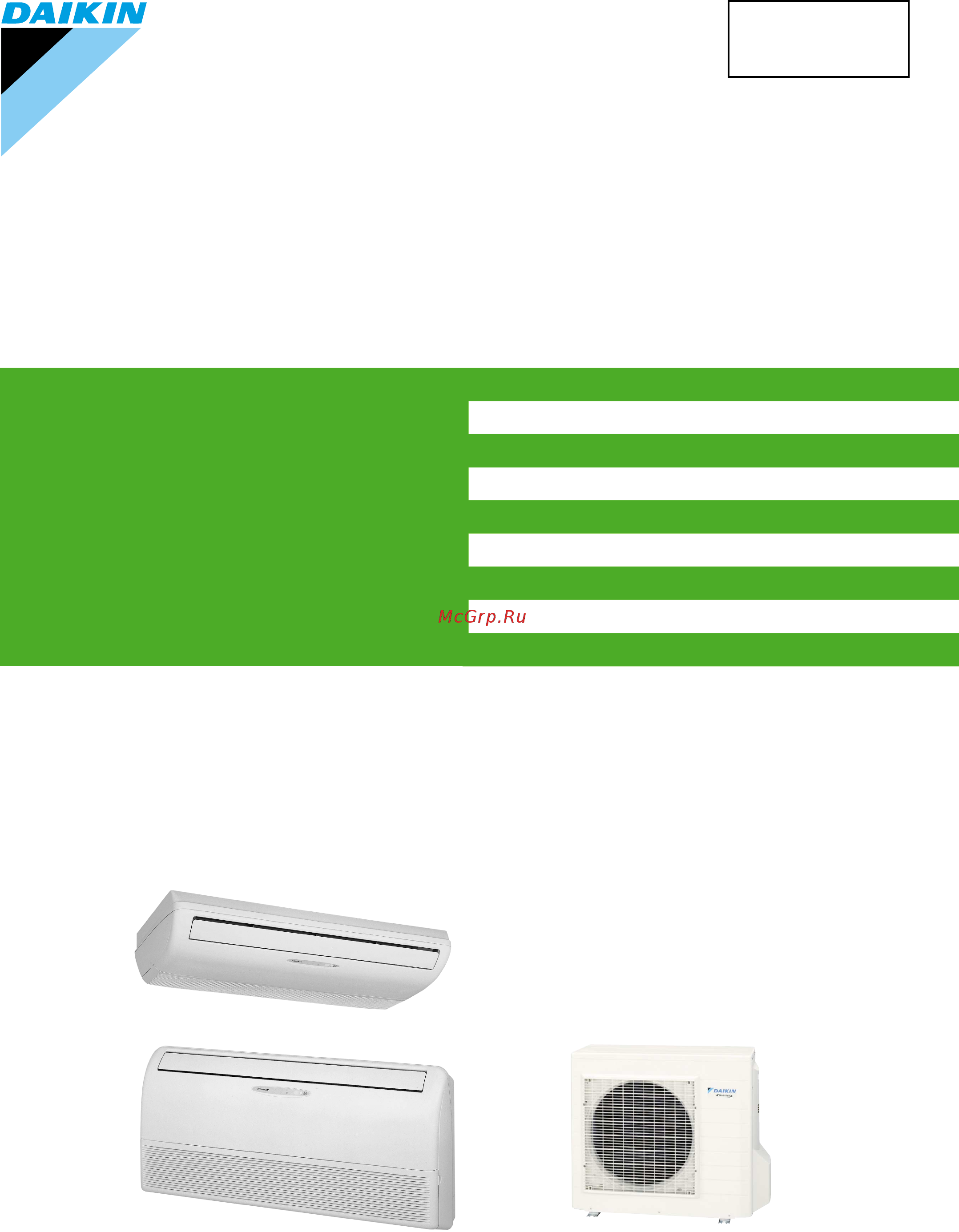
Floor / Ceiling Suspended Dual Type
B-Series
[Applied Models]
z
zz
zInverter Pair : Cooling Only
z
zz
zInverter Pair : Heat Pump
z
zz
zNon-Inverter Pair : Cooling Only
SiBE05-312
Service
Manual
Содержание
- Floor ceiling suspended dual type b series 1
- Inverter pair 1
- Manual 1
- Service 1
- Sibe05 312 1
- Connector wiring diagram 3
- Control specification 8 3
- Function of main structural parts 6 3
- Introduction v 3
- List of functions 3
- Main functions 6 3
- Part 1 list of functions 3
- Part 2 specifications 3
- Part 3 printed circuit board 3
- Part 4 function and control 5 3
- Printed circuit board connector wiring diagram 0 3
- Specifications 3
- Table of contents 3
- Caution for diagnosis 8 2 problem symptoms and measures 9 3 service check function 0 4 troubleshooting 1 4
- Check 02 4
- Indoor unit 12 4
- Part 5 system configuration 1 4
- Part 6 service diagnosis 7 4
- Part 7 removal procedure 11 4
- System configuration 2 2 instruction 3 4
- Drawings flow charts v 5
- Index i 5
- Others 54 5
- Outdoor unit 28 5
- Part 8 others 53 5
- Part 9 appendix 57 5
- Piping diagrams 58 5
- Wiring diagrams 60 5
- Caution in repair 6
- Introduction 6
- Safety cautions 6
- Warning 6
- Caution 7
- Cautions regarding products after repair 7
- Warning 7
- Caution 8
- Inspection after repair 8
- Warning 8
- Caution 9
- Icons are used to attract the attention of the reader to specific information the meaning of each icon is described in the table below 9
- Using icons 9
- Using icons list 9
- Warning 9
- Part 1 list of functions 10
- Holding functions no functions 11
- List of functions 11
- List of functions sibe05 312 11
- Holding functions no functions 12
- List of functions 3 12
- Sibe05 312 list of functions 12
- Part 2 specifications 14
- Cooling only 15
- Specifications 15
- Specifications sibe05 312 15
- V 50hz 15
- Heat pump 16
- Sibe05 312 specifications 16
- Specifications 7 16
- V 50hz 16
- Part 3 printed circuit board connector wiring diagram 18
- Indoor unit 19
- Printed circuit board connector wiring diagram 19
- Pcb 2 power supply pcb indoor unit 20
- Pcb 3 display pcb pcb 4 signal receiver pcb 20
- Pcb detail pcb 1 control pcb indoor unit 20
- Printed circuit board connector wiring diagram 11 20
- Sibe05 312 printed circuit board connector wiring diagram 20
- Outdoor unit 21
- Pcb 2 power supply pcb outdoor unit service monitor pc b 22
- Pcb detail pcb 1 control pcb outdoor unit 22
- Printed circuit board connector wiring diagram 13 22
- Sibe05 312 printed circuit board connector wiring diagram 22
- Printed circuit board connector wiring diagram 23
- Printed circuit board connector wiring diagram sibe05 312 23
- Control specification 8 24
- Function of main structural parts 6 24
- Main functions 6 24
- Part 4 function and control 24
- Part 4 part 4 part 4 part 4 function and control function and control function and control function and control 24
- Additional control parameters 25
- Drawing of inverter the following drawing shows a schematic view of the inverter principle 25
- Forced cooling operation 25
- Frequency principle 25
- Frequency restrictions 25
- Initial settings 25
- Inverter principle to regulate the capacity a frequency control is needed the inverter makes it possible to vary the rotation speed of the compressor the following table explains the conversion principle 25
- Main control parameters the compressor is frequency controlled during normal operation the target frequency is set by the following 2 parameters coming from the operating indoor unit 25
- Main functions 25
- Note see the list of functions for the functions applicable to different models 25
- The difference between the room temperature and the set temperature 25
- The load condition of the operating indoor unit 25
- The target frequency is adapted by additional parameters in the following cases 25
- Comfortable air conditioning a detailed adjustment is integrated to ensure a fixed room temperature it is possible to air condition with a small room temperature variation 26
- Energy saving heating and cooling once the set temperature is reached the energy saving operation enables to maintain the room temperature at low power 26
- Even during extreme cold weather the high capacity is achieved it is maintained even when the outside temperature is 2 c 26
- For more information refer to forced operation mode on page 26
- Forced cooling operation 26
- Frequency limits the following table shows the functions that define the minimum and maximum frequency 26
- Inverter features the inverter provides the following features 26
- Quick heating and quick cooling the compressor rotational speed is increased when starting the heating or cooling this enables a quick set temperature 26
- The regulating capacity can be changed according to the changes in the outside temperature and cooling heating load 26
- Auto swing 27
- Auto swing the following table explains the auto swing process for heating cooling dry and fan 27
- 60 71kw class 750 1000 rpm during powerful operation 1050 rpm 28
- Automatic air flow control for cooling 28
- Automatic air flow control for heating 28
- Control mode the airflow rate can be automatically controlled depending on the difference between the set temperature and the room temperature this is done through phase control and hall ic control 28
- Fan speed control for indoor units 28
- For more information about hall ic refer to the troubleshooting for fan motor on page 75 28
- Function and control 19 28
- H hh powerful 28
- Ll cooling thermostat off sl silent 28
- Note 1 during powerful operation fan operates h tap 50 90 rpm 2 fan stops during defrost operation 28
- Phase steps phase control and fan speed control contains 9 steps lll ll sl l ml m mh h and hh 28
- Sibe05 312 main functions 28
- Step cooling heating dry mode lll heating thermostat off 28
- The following drawing explains the principle for fan speed control for heating 28
- The following drawing explains the principle of fan speed control for cooling 28
- Within this range the airflow rate is automatically controlled when the fan setting button is set to automatic 28
- In case of inverter units the microcomputer automatically sets the temperature and fan settings the difference between the room temperature at startup and the temperature set by the microcomputer is divided into two zones then the unit operates in the dry mode with an appropriate capacity for each zone to maintain the temperature and humidity at a comfortable level 29
- Programme dry function 29
- Programme dry function removes humidity while preventing the room temperature from lowering since the microcomputer controls both the temperature and air flow volume the temperature adjustment and fan adjustment buttons are inoperable in this mode 29
- Automatic operation 30
- Night set mode 31
- Home leave operation 32
- Details of the control when powerful button is pushed in each operation mode the fan speed setting temperature will be converted to the following states in a period of twenty minutes 33
- Ex powerful operation in cooling mode 33
- Inverter powerful operation 33
- Outline in order to exploit the cooling and heating capacity to full extent operate the air conditioner by increasing the indoor fan rotating speed and the compressor frequency 33
- Tpf 20min 33
- Air purifying filter 34
- Auto restart function 34
- Hot start function 34
- Mold proof air filter 34
- On off button on indoor unit 34
- Other functions 34
- Photocatalytic deodorizing filter 34
- Self diagnosis digital display 34
- Signal receiving sign 34
- Function of main structural parts 35
- Function of thermistor 35
- Heat pump model 35
- Cooling only model 36
- Control specification 37
- Control specification sibe05 312 37
- Detail 1 for heat pump model there are following modes stop cooling includes drying heating include defrosting 37
- For cooling only model there are following models stop and cooling including drying 37
- Function and control 37
- Mode hierarchy 37
- Note unless specified otherwise an indoor dry operation command must be regarded as cooling operation 37
- Outline there are two modes the mode selected in user s place normal air conditioning mode and forced operation mode for installation and providing service 37
- Frequency control 38
- D signal 1 p control calculate 39
- D signal and is used for frequency command 39
- D signal the difference between a room temperature and the temperature set by the remote controller will be taken as the 39
- D value in each sampling time 20 seconds and adjust the frequency according to its difference from the frequency previously calculated 2 i control if the operating frequency is not change more than a certain fixed time adjust the frequency up and down according to the 39
- D value is large increase the frequency 3 limit of frequency variation width when the difference between input current and input current drooping value is less than 1 a the frequency increase width must be limited 4 frequency management when other controls are functioning 39
- D value is small lower the frequency when the 39
- D value obtaining the fixed 39
- D value of the indoor unit and the q value of the indoor unit q value indoor unit output determined from indoor unit volume air flow rate and other factors 39
- D value when the 39
- Determine lower limit frequency 39
- For limiting lower limit frequency management is carried out only when the frequency rises 5 upper and lower limit of frequency by pi control the frequency upper and lower limits are set depending on indoor unit when low noise commands come from the indoor unit or when outdoor unit low noise or quiet commands come from indoor unit the upper limit frequency must be lowered than the usual setting 39
- Frequency initial setting 39
- Indoor frequency command 39
- Outline when starting the compressor or when conditions are varied due to the change of the room the frequency must be initialized according to the total of a maximum 39
- Pi control determine frequency up down by 39
- Set a maximum value as an lower limit frequency among the frequency lower limits of the following functions pressure difference upkeep 4 determine prohibited frequency 39
- Th off thermostat off 39
- There is a certain prohibited frequency such as a power supply frequency 39
- When frequency is drooping frequency management is carried out only when the frequency droops 39
- 3 minutes stand by 40
- Compressor protection function 40
- Controls at mode changing start up 40
- Four way valve operation compensation 40
- Four way valve switching 40
- Preheating operation 40
- Discharge pipe temperature control 41
- Input current control 41
- Freeze up protection control 42
- Heating peak cut control 42
- Fan control 43
- Moisture protection function 2 43
- Defrost control 44
- Detail conditions for starting defrost the starting conditions must be made with the outdoor air temperature and heat exchanger temperature under the conditions that the system is in heating operation 6 minutes after the compressor is started and more than 44 minutes of accumulated time pass since the start of the operation or ending the defrosting conditions for canceling defrost the judgment must be made with heat exchanger temperature 4 c 12 c 44
- Detail separate into zones 44
- Function and control 35 44
- Low hz high pressure limit 44
- Note drooping the system stops 2 minutes after staying in the drooping zone 44
- Outline heat pump only defrosting is carried out by the cooling cycle reverse cycle the defrosting time or outdoor heat exchanger temperature must be more than its fixed value when finishing 44
- Outline heat pump only set the upper limit of high pressure in a low hz zone set the upper limit of the indoor heat exchanger temperature by its operating frequency of hz separate into three zones reset zone unchanged zone and drooping zone and the frequency control must be carried out in such zones 44
- Sibe05 312 control specification 44
- Control specification sibe05 312 45
- Detail the followings are the examples of control which function in each mode by the electronic expansion valve control 45
- Electronic expansion valve control 45
- Function and control 45
- Outline the following items are included in the electronic expansion valve control electronic expansion valve is fully closed 1 electronic expansion valve is fully closed when turning on the power 2 pressure equalizing control open control 1 electronic expansion valve control when starting operation 2 control when frequency changed 3 control for defrosting only for heat pump model 4 control when a discharge pipe temperature is abnormally high 5 control when the discharge pipe thermistor is disconnected feedback control 1 discharge pipe temperature control 45
- Disconnection of the discharge pipe thermistor 46
- Fully closing with power on 46
- High temperature of the discharge pipe 46
- Opening limit 46
- Pressure equalization control 46
- Starting operation control 46
- Control when frequency is changed 47
- Target discharge pipe temperature control 47
- Detection of overload and over current 48
- Insufficient gas control 48
- Malfunctions 48
- Sensor malfunction detection 48
- Additional function 49
- Compressor operating frequency is increased to p1 max max hz of operating room and outdoor unit airflow rate is increased 49
- Detail forced cooling 49
- Forced operation mode 49
- Outline forced operating mode includes only forced cooling 49
- Power supply voltage is detected each time equipment operation starts 49
- Powerful operation mode 49
- Voltage detection function 49
- Part 5 part 5 part 5 part 5 system configuration system configuration system configuration system configuration 50
- Part 5 system configuration 50
- System configuration 2 2 instruction 3 50
- System configuration 51
- Caution 52
- Instruction 52
- Safety precautions 52
- Warning 52
- Consider nuisance to your neighbours from noises 53
- Electrical work 53
- Installation site 53
- System relocation 53
- Caution 54
- I indoor unit 54
- I opening the front grille 54
- Names of parts 54
- I outdoor unit 55
- Iiii outdoor unit 55
- Indoor unit 55
- Arc433a5 a6 56
- I remote controller 56
- Attention 57
- I to set the batteries 57
- Preparation before operation 57
- Attention 58
- Choose a place from where the sig nals reach the unit 58
- Fix the holder to a wall a pillar etc with the screws supplied with the holder 58
- I to fix the remote controller holder on the wall 58
- I to operate the remote controller 58
- Place the remote controller in the remote controller holder 58
- Receiver 58
- Remote controller holder 58
- To remove pull it upwards 58
- Be careful not to cool heat the room too much keeping the temperature setting at a moderate level helps save energy 59
- C for heating 2 59
- Cancel 59
- Clogged air filters cause inefficient operation and waste energy clean them once in about every two weeks 59
- Cover windows with a blind or a curtain blocking sunlight and air from outdoors increases the cooling heating effect 59
- For cooling 2 59
- I to set the clock 59
- I turn the breaker on 59
- If you are not going to use the air conditioner for a long period for example in spring or autumn turn the breaker off 59
- Instruction sibe05 312 59
- Operation outside this humidity or temperature range may cause a safety device to disable the system 59
- Press clock button 59
- Press timer setting button to set the clock to the present time 59
- Recommended temperature setting 59
- Silent 59
- System configuration 59
- The air conditioner always consumes 15 35 watts of electricity even while it is not operating 59
- Use the air conditioner in the following conditions 59
- Auto dry cool heat fan operation 60
- I to change the temperature setting 60
- I to start operation 60
- I to stop operation 60
- Press mode selector button and select a operation mode 60
- Press on off button 60
- Press on off button again 60
- Press temperature adjustment button 60
- I to change the air flow direction 61
- I to change the air flow rate setting 61
- Press fan setting button 61
- Adjusting the air flow direction 62
- I to adjust the horizontal blade flap 62
- I to adjust the vertical blades louvres 63
- Notes on flap and louvres angles 63
- I to cancel powerful operation 64
- I to start powerful operation 64
- Powerful operation 64
- I to cancel outdoor unit silent operation 65
- I to start outdoor unit silent operation 65
- Outdoor unit silent operation 65
- Before using home leave operation 66
- Home leave operation 66
- I to cancel home leave operation 66
- I to start home leave operation 66
- To set the temperature and air flow rate for home leave operation 66
- I useful in these cases 67
- I what s the home leave operation 67
- Use as a favorite mode 67
- Use as an energy saving mode 67
- I to cancel the off timer operation 68
- I to use off timer opera tion 68
- Timer operation 68
- Attention 69
- I to cancel on timer operation 69
- I to combine on timer and off timer 69
- I to use on timer operation 69
- Press cancel button 69
- Press on timer button 69
- Press on timer button again 69
- Press timer setting button until the time setting reaches the point you like 69
- Before cleaning be sure to stop the operation and turn the breaker off 70
- Care and cleaning 70
- Caution 70
- Clean the front grille 70
- Close the front grille 70
- I front grille 70
- I indoor unit outdoor unit and remote controller 70
- Open the front grille 70
- Wipe them with dry soft cloth 70
- Clean or replace each filter 71
- Detach the filter element and attach a new one 71
- Dry the photocatalytic deodorizing filter in the sun 71
- Filters 71
- I air filter 71
- I air purifying filter green 71
- I photocatalytic deodorizing filter gray 71
- Maintenance 71
- Open the front grille page 22 2 pull out the air filters 71
- Replace approximately once every 3 months 71
- Replacement 71
- See below 71
- Set the air filter air purifying filter and photocatalytic deodorizing filter as they were and close the front grille 71
- Take off the air purifying filter photocatalytic deodorizing filter 71
- Wash the air filters with water or clean them with vacuum cleaner 71
- 1 the paper material is torn or broken during cleaning 72
- Air purifying filter with frame 72
- Air purifying filter without frame 72
- Clean the air filters and set them again 72
- Dispose of old air filters as non burnable waste and 72
- Filters as burnable waste 72
- I before a long idle period 72
- Operate the fan only for several hours on a fine day to dry out the inside 72
- Photocatalytic deodorizing filter with frame 72
- Photocatalytic deodorizing filter without frame 72
- Press mode button and select fan operation 72
- Press on off button and start operation 72
- Take out batteries from the remote controller 72
- Turn off the breaker for the room air conditioner 72
- Case explanation 73
- These cases are not troubles 73
- Troubleshooting 73
- Case check 74
- Check again 74
- Call the service shop immediately 75
- Disposal requirements 75
- I the power cord is abnormally hot or damaged i an abnormal sound is heard during operation i the safety breaker a fuse or the earth leakage breaker cuts off the operation frequently i a switch or a button often fails to work properly i there is a burning smell i water leaks from the indoor unit 75
- Turn the breaker off and call the service shop 75
- Warning 75
- We recommend periodical maintenance 75
- Caution for diagnosis 8 2 problem symptoms and measures 9 3 service check function 0 4 troubleshooting 1 76
- Check 02 76
- Part 6 part 6 part 6 part 6 service diagnosis service diagnosis service diagnosis service diagnosis 76
- Part 6 service diagnosis 76
- Caution for diagnosis 77
- Problem symptoms and measures 78
- Arc433a5 a6 79
- In the arc433a series remote controller the temperature display sections on the main unit indicate corresponding codes 1 when the timer cancel button is held down for 5 seconds a 00 indication flashes on the temperature display section 79
- Note 1 a short beep and two consecutive beeps indicate non corresponding codes 2 to cancel the code display hold the timer cancel button down for 5 seconds the code display also cancels itself if the button is not pressed for 1 minute 79
- Press the timer cancel button repeatedly until a continuous beep is produced 79
- Service check function 79
- The code indication changes in the sequence shown below and notifies with a long beep 79
- Displayed only when system down occurs 80
- Error codes and description 80
- Troubleshooting 80
- Indoor unit pcb abnormality 81
- Freeze up protection control or high pressure control 82
- Caution be sure to turn off power switch before connect or disconnect connector or parts damage may be occurred 83
- Check no refer to p 04 83
- Note if the outside temperature is below 10 c in the cooling mode the system may get interrupted with error a5 displayed the system will be reset itself but this stop will be put in the error history memory 83
- Service diagnosis 83
- Troubleshooting 83
- Troubleshooting sibe05 312 83
- Check no 6 refer to p 10 84
- Fan motor ac motor or related abnormality 84
- Malfunction decision conditions 84
- Method of malfunction detection 84
- Operation halt due to short circuit inside the fan motor winding operation halt due to breaking of wire inside the fan motor operation halt due to breaking of the fan motor lead wires operation halt due to faulty capacitor of the fan motor detection error due to faulty indoor unit pcb 1 84
- Remote controller display 84
- Service diagnosis 75 84
- Sibe05 312 troubleshooting 84
- Supposed causes 84
- The rotation speed detected by the hall ic during fan motor operation is used to determine abnormal fan motor operation 84
- Troubleshooting 84
- When the detected rotation speed is less than 50 of the hh tap under maximum fan motor rotation demand 84
- Thermistor or related abnormality indoor unit 85
- Check no 0 refer to p 07 86
- Faulty indoor unit pcb 86
- Faulty outdoor unit pcb 86
- Indoor unit outdoor unit signal transmission error due to breaking of wire in the connection wires between the indoor and outdoor units wire no 2 86
- Indoor unit outdoor unit signal transmission error due to disturbed power supply waveform 86
- Indoor unit outdoor unit signal transmission error due to wiring error 86
- Malfunction decision conditions 86
- Method of malfunction detection 86
- Remote controller display 86
- Service diagnosis 77 86
- Sibe05 312 troubleshooting 86
- Signal transmission error between indoor and outdoor units 86
- Supposed causes 86
- The data received from the outdoor unit in indoor unit outdoor unit signal transmission is checked whether it is normal 86
- Troubleshooting 86
- When the data sent from the outdoor unit cannot be received normally or when the content of the data is abnormal 86
- A compressor overload is detected through compressor ol 87
- Check no 1 refer to p 07 87
- Check no refer to p 02 87
- Check no refer to p 03 87
- Check no refer to p 04 87
- Electronic expansion valve defective 87
- Four way valve malfunctioning 87
- If the compressor ol is activated twice the system will be shut down 87
- Malfunction decision conditions 87
- Method of malfunction detection 87
- Ol activation compressor overload 87
- Outdoor unit pcb defective 87
- Refrigerant shortage 87
- Remote controller display 87
- Service diagnosis 87
- Stop valve defective 87
- Supposed causes 87
- The error counter will reset itself if this or any other error does not occur during the following 60 minute compressor running time total time 87
- The operating temperature condition is not specified 87
- Troubleshooting 87
- Troubleshooting sibe05 312 87
- Water mixed in the local piping 87
- A compressor lock is detected by checking the compressor running condition through the position detection circuit 88
- Clearing condition continuous run for about 5 minutes normal 88
- Compressor lock 88
- Compressor locked 88
- Malfunction decision conditions 88
- Method of malfunction detection 88
- Remote controller display 88
- Seconds after the compressor has started the position detection circuit detects a compressor frequency of above 180 hz 88
- Service diagnosis 79 88
- Sibe05 312 troubleshooting 88
- Supposed causes 88
- The position detection circuit detects a compressor frequency of below 10 hz for 20 seconds or a frequency of above 160 hz 88
- The system will be shut down if the error occurs 16 times 88
- Troubleshooting 88
- Dc fan lock 89
- Input over current detection 90
- Caution be sure to turn off power switch before connect or disconnect connector or parts damage may be occurred 91
- Check no 4 refer to p 09 91
- Check no refer to p 05 91
- Check no refer to p 06 91
- Service diagnosis 91
- Troubleshooting 91
- Troubleshooting sibe05 312 91
- Four way valve abnormality 92
- Caution be sure to turn off power switch before connect or disconnect connector or parts damage may be occurred 93
- Check no 1 refer to p 07 93
- Check no refer to p 03 93
- Check no refer to p 04 93
- Service diagnosis 93
- Troubleshooting 93
- Troubleshooting sibe05 312 93
- Discharge pipe temperature control 94
- A compressor startup failure is detected by checking the compressor running condition through the position detection circuit 95
- Check no 3 refer to p 08 95
- Clearing condition continuous run for about 5 minutes normal 95
- Compressor itself defective 95
- Compressor relay cable disconnected 95
- Input voltage out of specification 95
- Malfunction decision conditions 95
- Method of malfunction detection 95
- Outdoor unit pcb defective 95
- Position sensor abnormality 95
- Remote controller display 95
- Service diagnosis 95
- Stop valve closed 95
- Supposed causes compressor relay cable disconnected 95
- The compressor fails to start in about 15 seconds after the compressor run command signal is sent 95
- The system will be shut down if the error occurs 16 times 95
- Troubleshooting 95
- Troubleshooting sibe05 312 95
- Ct or related abnormality 96
- Caution be sure to turn off power switch before connect or disconnect connector or parts damage may be occurred 97
- Check no 2 refer to p 08 97
- Service diagnosis 97
- Troubleshooting 97
- Troubleshooting sibe05 312 97
- P4 j3 j6 h9 98
- Thermistor or related abnormality outdoor unit 98
- Caution be sure to turn off power switch before connect or disconnect connector or parts damage may be occurred 99
- Check no refer to p 04 99
- P4 radiation fin thermistor j3 discharge pipe thermistor j6 outdoor heat exchanger thermistor h9 outdoor air thermistor 99
- Service diagnosis 99
- Troubleshooting 99
- Troubleshooting sibe05 312 99
- Electrical box temperature rise 100
- Caution be sure to turn off power switch before connect or disconnect connector or parts damage may be occurred 101
- Check no refer to p 04 101
- Check no refer to p 05 101
- Check no refer to p 06 101
- Service diagnosis 101
- Troubleshooting 101
- Troubleshooting sibe05 312 101
- Radiation fin temperature rise 102
- Caution be sure to turn off power switch before connect or disconnect connector or parts damage may be occurred 103
- Check no refer to p 04 103
- Check no refer to p 05 103
- Check no refer to p 06 103
- Service diagnosis 103
- Troubleshooting 103
- Troubleshooting sibe05 312 103
- Output over current detection 104
- Caution be sure to turn off power switch before connect or disconnect connector or parts damage may be occurred 105
- Check no 3 refer to p 08 105
- Check no refer to p 05 105
- Check no refer to p 06 105
- Service diagnosis 105
- Troubleshooting 105
- Troubleshooting sibe05 312 105
- Insufficient gas 106
- Caution be sure to turn off power switch before connect or disconnect connector or parts damage may be occurred 107
- Check no refer to p 02 107
- Check no refer to p 04 107
- Service diagnosis 107
- Troubleshooting 107
- Troubleshooting sibe05 312 107
- An abnormal voltage rise or drop is detected by checking the detection circuit or dc voltage detection circuit 108
- An over voltage signal is fed from the over voltage detection circuit to the microcomputer or the voltage being detected by the dc voltage detection circuit is judged to be below 150 v for 0 second 108
- Clearing condition continuous run for about 60 minutes normal 108
- Low voltage detection 108
- Malfunction decision conditions 108
- Method of malfunction detection 108
- Over voltage detector or dc voltage detection circuit defective 108
- Pam control part s defective 108
- Remote controller display 108
- Service diagnosis 99 108
- Sibe05 312 troubleshooting 108
- Supply voltage not as specified 108
- Supposed causes 108
- The system will be shut down if the error occurs 16 times 108
- Troubleshooting 108
- High pressure control in cooling 109
- Caution be sure to turn off power switch before connect or disconnect connector or parts damage may be occurred 110
- Check no refer to p 02 110
- Check no refer to p 04 110
- Check no refer to p 05 110
- Check no refer to p 06 110
- Service diagnosis 101 110
- Sibe05 312 troubleshooting 110
- Troubleshooting 110
- Electronic expansion valve check 111
- How to check 111
- Check no 112
- Four way valve performance check 112
- Service diagnosis 103 112
- Sibe05 312 check 112
- Check no remove the connectors of the thermistors on the pcb and measure the resistance of each thermistor using tester the relationship between normal temperature and resistance is shown in the graph and the table below 113
- Thermistor resistance check 113
- Check no 114
- Installation condition check 114
- Service diagnosis 105 114
- Sibe05 312 check 114
- Check no 115
- Check sibe05 312 115
- Discharge pressure check 115
- Outdoor unit fan system check with dc motor 115
- Service diagnosis 115
- Check no 0 measure the power supply waveform between pins 1 and 3 on the terminal board and check the waveform disturbance 116
- Check no 1 116
- Check to see if the power supply waveform is a sine wave fig 116
- Check to see if there is waveform disturbance near the zero cross sections circled in fig 116
- Fig fig 116
- Inverter units refrigerant system check 116
- Power supply waveforms check 116
- Service diagnosis 107 116
- Sibe05 312 check 116
- Capacitor voltage check 117
- Check no 2 before this checking be sure to check the main circuit for short circuit 117
- Check no 3 117
- Checking the capacitor voltage 117
- Checking the power transistor 117
- For the uvw make measurements at the faston terminal on the board or the relay connector 117
- If unavoidably necessary to touch a live part make sure the power transistor s supply voltage is below 50 v using the tester 117
- Never touch any live parts for at least 10 minutes after turning off the circuit breaker 117
- Power transistor check 117
- With the circuit breaker still on measure the voltage according to the drawing of the model in question be careful never to touch any live parts 117
- Main circuit electrolytic capacitor check 118
- Turning speed pulse input on the outdoor unit pcb check 118
- Hall ic check 119
- Indoor unit 12 120
- Outdoor unit 28 120
- Part 7 part 7 part 7 part 7 removal procedure removal procedure removal procedure removal procedure 120
- Part 7 removal procedure 120
- Indoor unit 121
- Removal of the air filter front grille 121
- Removal of the front panel 124
- Removal of the horizontal blade 126
- Removal of the signal receiver unit swing motor 127
- Removal of the discharge grille 128
- Removal of the drain pan 129
- Removal of the electrical box pcb 130
- Disconnect the terminals from the terminal strip board 131
- Indoor unit sibe05 312 131
- Removal procedure 131
- Step procedure points 131
- The illustration shows the control pcb indoor unit 131
- Removal of the fan rotor fan motor 133
- Removal of the heat exchanger 135
- Outdoor unit 137
- Removal of the panels and plates 137
- Removal of the fan motor propeller fan 141
- Pull the fan motor out 144
- Put the lead wire through the back of the motor when reassembling so as not to be entangled with the propeller fan 144
- Removal of the pcb electrical box 145
- Disconnect the reactor harness 150
- Disconnect the relaying wire connector for the compressor 150
- Release the clamp by pliers 150
- Loosen the screw of the electrical box 151
- Pull the clamp and draw the thermistor harness out from the back of the electrical box 151
- Lift the electrical box and remove it 152
- Release the clamp of the four way valve harness 152
- Removal of the reactor 153
- Lift the partition plate and remove it 154
- Loosen the screw slide the reactor and remove it from the partition plate 154
- Removal of the sound blanket 155
- Removal of the four way valve 157
- Removal of the electronic expansion valve 158
- Removal of the compressor 159
- Part 8 others 162
- Others 163
- Test run from the remote controller 163
- Control pcb of the indoor unit 1 remove the front grille 3 screws 2 remove the electrical box 1 screw 3 remove the drip proof plate 4 tabs 4 cut the address jumper ja on the control pcb 164
- How to set the different addresses 164
- Jumper setting 164
- Jumper settings 164
- When two indoor units are installed in one room the two wireless remote controllers can be set for different addresses 164
- When two units are installed in one room 164
- Wireless remote controller 1 slide the front cover and take it off 2 cut the address jumper j4 164
- Part 9 appendix 166
- Flks50bvmb flxs50bvmb 167
- Indoor units 167
- Piping diagrams 167
- Appendix 159 168
- Outdoor units 168
- Rks50bvmb rs50bvmb 168
- Rxs50bvmb 168
- Sibe05 312 piping diagrams 168
- Appendix 169
- Flks50bvmb flxs50bvmb 169
- Indoor units 169
- Wiring diagrams 169
- Wiring diagrams sibe05 312 169
- Appendix 161 170
- Outdoor units 170
- Rks50bvmb rs50bvmb 170
- Rxs50bvmb 170
- Sibe05 312 wiring diagrams 170
- Index index index index 172
- Numerics 172
- Wiring diagrams 60 175
- Drawings flow charts 176
- Drawings flow charts drawings flow charts drawings flow charts drawings flow charts 176
- For further improvement specifications or designs are subject to change without prior notice 178
- Printed in singapore 06 2003 ak cos 178
Похожие устройства
- Delonghi KBI2001.CP Инструкция по эксплуатации
- Delonghi KBI2001.BK Инструкция по эксплуатации
- Delonghi KBI2001.BZ Инструкция по эксплуатации
- Delonghi KBI2001.W Инструкция по эксплуатации
- Noname GLIDE UNISEX 200K (GLU2PE1001) Инструкция по эксплуатации
- Philips HX6032/33 Kids бережное очищение для детей, 3+ Инструкция по эксплуатации
- Philips HX6042/33 Kids бережное очищение для детей, 7+ Инструкция по эксплуатации
- Espresso Italia Cremoso 10 шт Инструкция по эксплуатации
- Espresso Italia Intenso 10 шт Инструкция по эксплуатации
- Bosch BBH21621 Инструкция по эксплуатации
- Gorenje ECT6SY2B Инструкция по эксплуатации
- Nescafe Dolce Gusto Cortado 16 шт Инструкция по эксплуатации
- ORIGO Kaffee Klassik Barista Espresso 500 г Инструкция по эксплуатации
- ORIGO Kaffee Cafe Crema Gourmetrostung 500 г Инструкция по эксплуатации
- Philips GC4922/80 Инструкция по эксплуатации
- Braun BT3040 Инструкция по эксплуатации
- Gama XWIDE DIG PTC AF Инструкция по эксплуатации
- Hansa ZWM 607 IEH Инструкция по эксплуатации
- Rommelsbacher BG 1805/E Инструкция по эксплуатации
- Steba PG 4.3 Инструкция по эксплуатации