
Icom MR-1000T2 Инструкция по эксплуатации онлайн
INSTRUCTION MANUAL
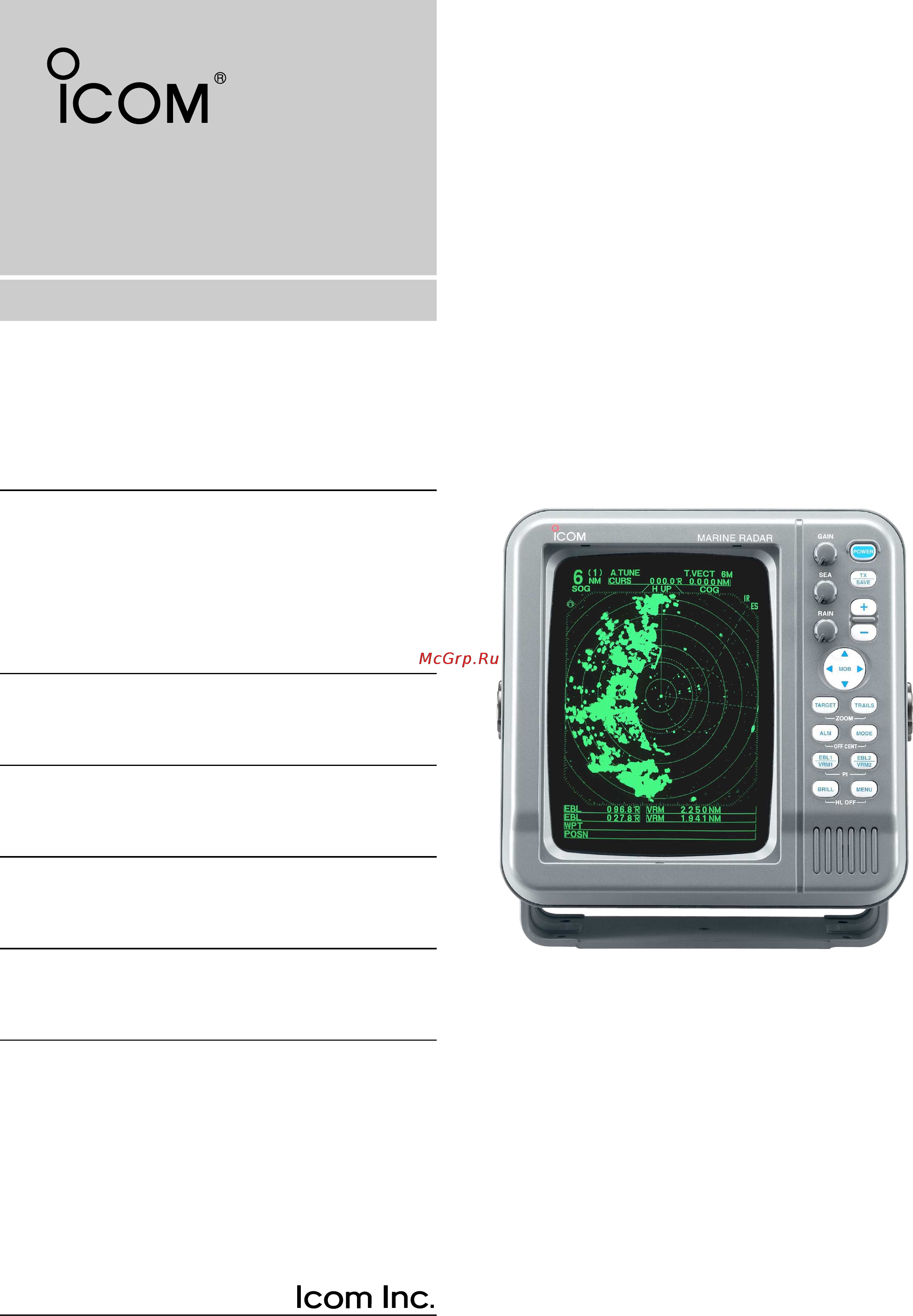
MARINE RADAR
MR-1000R™
(Radome type)
MR-1000T™
(Open array type)
MR-1000R2_T2.qxd 04.2.24 10:22 Page 1
Содержание
- Supplied accessories 2
- System components 2
- Be careful 3
- Explicit definitions 3
- Follow the settings as below to detect the sart signal on the screen 3
- Foreword 3
- Important 3
- Precaution 3
- Q select the screen range between 6 nm to 12 nm with p 2 w set the gain as high as possible p 3 e set the sea to minimum p 3 r set the rain to minimum p 3 t turn the ir off y turn the stretch off 3
- R neve 3
- Read all instructions 3
- Sart signal may not be detected and may not be displayed on the screen depending on the sea rain or ir settings 3
- Save this instruction manual 3
- Table of contents 4
- Caution 5
- Danger high voltage 5
- Radiation hazard 5
- Panel description 6
- I screen 8
- I function 10
- I video 10
- I ata automatic tracking aid 11
- I int setting 11
- Basic operation 12
- I checking the installation 12
- I turning power on off 12
- I basic operation 13
- I off center function 14
- I rain function 14
- I sea function 14
- Warning 14
- I ir function 15
- I stretch function 15
- I zoom function 15
- I power save function 16
- I trails function 16
- I bearing setting 17
- I long pulse function 17
- I position indication 17
- I ship speed indication 17
- I waypoint indication 17
- Distance and direction measurements 18
- I distance measurement 18
- D using the ebl and vrm q push ù ú 19
- Distance and direction measurements 19
- E push ebl1 vrm1 to clear the ebl1 and vrm1 19
- I bearing and distance measurement 19
- R push ù ú ω to move the cursor on the desired target t push ebl2 vrm2 to display the ebl2 and vrm2 on the display 19
- This radar has 2 electronic bearing lines ebl to in dicate the target direction from your ship or a target 19
- To move the cursor on the desired target w push ebl1 vrm1 to display the ebl1 and vrm1 19
- Y to clear the ebl1 and vrm1 push ebl1 vrm1 19
- I advanced measurements 20
- Alarm function 21
- I alarm zone setting 21
- I zone alarm setting 21
- Ata automatic tracking aid 22
- I ata automatic tracking aid 22
- I ata menu setting 22
- Ata automatic tracking aid 23
- Brg 305 t 23
- Brg cse cpa 23
- Cse 081 t cpa 5 nm 23
- Dist 11 3nm spd 12 kt tcpa 0 50 23
- Dist spd tcpa 23
- I ata operation 23
- I course and speed vector 23
- I plotting marks 23
- Q push ù ú ω to move the cursor on the de sired target w push target for 1 sec to select the tar get for tracking 23
- Select the target which you want to track on the dis play 23
- Selected uncalculated mark selected calculated mark normal calculated mark cpa tcpa alarm mark the target is close to within a minimum range and time alarm emit indicator push tar get to cancel the alarm when the tracking of a target disap pears 23
- The vector indicates the target s predicted true or rel ative course and speed 23
- There are 5 kinds of plotting marks 23
- I plots 24
- Basic radar theory 25
- I indirect echoes 25
- I side lobe echoes 25
- I minimum range 26
- I multiple echoes 26
- Basic radar theory 27
- Blind or shadow sectors may exist because of ob structions such as masts derricks or stacks an ob struction may throw either a complete or partial shadow as shown in the diagram below if a target is in a shadow sector target echoes may not appear on the screen 27
- D direction resolution 27
- D distance resolution 27
- I blind and shadow sectors 27
- I target resolution 27
- Target resolution is determined by the horizontal beam width and transmit pulse width sometimes it is difficult to detect two targets which are separated by short dis tances or which are in the same direction 27
- When tall and massive targets such as a large island are located at close range also shadowed without pro ducing any echoes this phenomenon is called blind sector it is very important to know the bearings and widths of all shadow sectors caused by your own ship s obstructions 27
- When two targets are not separated by more than the horizontal beam width they appear as one echo 27
- When two targets are not separated by more than the pulse width they appear as 1 echo 27
- When two targets are separated by more than the horizontal beam width they appear as two echoes 27
- When two targets are separated by more than the pulse width they appear as two echoes 27
- I connecting the units 28
- I ground connection 28
- I power source requirement 28
- Installation and connections 28
- I installing the display unit 29
- I mounting the ex 2714 scanner unit 30
- Warning 30
- Caution 31
- I wiring the ex 2714 system cable 31
- I mounting the ex 2780 scanner unit 32
- Warning 32
- Caution 33
- I wiring the ex 2780 system cable 33
- I fixing the ex 2780 scanner unit 34
- Other functions 35
- I select the language 36
- I service man menu 36
- Service man menu 36
- I hdg adjustment 37
- I timing adjustment 37
- I range selection 38
- I spd adjustment 38
- Error message 39
- I error message list 39
- I display unit maintenance 40
- I options 40
- I periodic maintenance 40
- I scanner unit maintenance 40
- Maintenance 40
- Warning 40
- D general 41
- D scanner unit 41
- Specifications 41
- D display unit 42
- External data list 43
- Nmea1 and nmea2 connectors see p 24 hdt hdm rmc gga gll vtg wpl gns and bwc are sentences of the nmea0183 if brg input is set to gps rmc of nmea2 connector or cog course over the ground of vtg a bow it receives as a direction even if there is no direction information compass etc in nmea1 connector the screen display of the north rise etc is possible however direction accuracy falls when the speed of a ship is set to 2 or less kts or when exceeding 3 kts a bow it does not receive as direction data moreo the influence of measurement position accuracy or a current an actual bow it may differ from a direction 43
- Og over ground tw through the water 43
- The following external bearing speed position and way point data is are required when you use the radar func tions 43
- Sx 2713 2779 display mounting bracket template 44
- Ex 2714 radome template 45
- Ship s bow direction 45
- Ex 2780 open array type template 46
- Ship s bow direction 46
- 1 32 kamiminami hirano ku osaka 547 0003 japan 47
Похожие устройства
- Asko C9505 A42002006 RU WHITE FS 50 Инструкция по эксплуатации
- Bosch KGE36AW30R Инструкция по эксплуатации
- Icom IC-PCR100 Инструкция по эксплуатации
- Asko C9510 A42002003 RU WHITE FS 50 Инструкция по эксплуатации
- Siemens KG39EAW20R Инструкция по эксплуатации
- Icom IC-PCR1000 Инструкция по эксплуатации
- Asko C9535 A42002022 RU WHITE FS 50 Инструкция по эксплуатации
- Siemens KG36EAL20R Инструкция по эксплуатации
- Icom IC-R1500 Инструкция по эксплуатации
- Bosch KGE36AI20R Инструкция по эксплуатации
- Asko C9540 A42002017 RU WHITE FS 50 Инструкция по эксплуатации
- Icom IC-PCR1500 Инструкция по эксплуатации
- Bosch KGE39AW30R Инструкция по эксплуатации
- Asko C9545 A42002025 RU WHITE FS 50 Инструкция по эксплуатации
- Icom IC-PCR2500 Инструкция по эксплуатации
- Siemens KG39EAL20R Инструкция по эксплуатации
- Asko C955 A527C52A RU WHITE FS 50 Инструкция по эксплуатации
- Icom IC-R2 Инструкция по эксплуатации
- Siemens KG39EAW30R Инструкция по эксплуатации
- Asko C9555 A42002023 RU WHITE FS 50 Инструкция по эксплуатации