![Motorola MotoTRBO DM2600 [25/92] Wire diagram](/img/pdf.png)
Motorola MotoTRBO DM2600 [25/92] Wire diagram
![Motorola MotoTRBO DM2600 [25/92] Wire diagram](/views2/1781232/page25/bg19.png)
Test Equipment and Service Aids: Programming Cables 2-3
2.3 Programming Cables
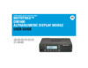
Figure 2-1 Front Telco MMP USB Programming Cable PMKN4147_
Figure 2-2 Back 20 Pin MAP USB Programming Cable PMKN4148_
2.4 Programming and Test Cable
Figure 2-3 Back 20 Pin MAP Test and USB Programming Cable PMKN4149_
20
2
19
1
15
17
16
18
14
915±15
CABLE
1455±24
CABLE
TO MOBILE RADIO
ACCESSORY
CONNECTOR
VIEWED FROM
FRONT (PIN END)
OF CONNECTOR
USB CONNECTORDB 25 CONNECTOR
20
2
19
115
17
16
18
1
14 25
13
1
14
25
13
WIRE DIAGRAM
20 PIN
ACCESSORY PORT CONNECTOR
USB DB25P
PIN 19 VCC (5v) (USB VBUS) PIN 1
PIN 18 DATA - PIN 2
PIN 17 DATA + PIN 3
PIN 20
GROUND (USB) PIN 4
DRAIN WIRE AND BRAID SHELL
PIN 1 SPEAKER - PIN 2 & 7
PIN 2 EXT MIC AUDIO PIN 10 & 15
PIN 3 PROGM INPUT (EXT. PTT) PIN 20
PIN 7 GROUND (DB25) PIN 16
WIRE COLOUR
RED
WHITE
GREEN
BLACK
DRAIN WIRE/BRAID
ORANGE
GREY
PINK
PIN 5 FLAT TX AUDIO YELLOW PIN 18
BLACK
PIN 15 RSSI BROWN PIN 19
PIN 16 SPEAKER + PURPLE PIN 1 & 5
Содержание
- Attention p.3
- Computer software copyrights p.3
- Before using the mobile two way product dm2600 read the rf energy exposure and safety guide that ships with the radio which contains important operating instructions for safe usage and rf energy awareness and control for compliance with applicable standards and regulations p.3
- Disclaimer p.3
- Document copyrights p.3
- These servicing instructions are for use by qualified personnel only to reduce the risk of electric shock do not perform any servicing other than that contained in the operating instructions unless you are qualified to do so refer all servicing to qualified service personnel p.3
- Product safety and rf exposure compliance p.3
- Foreword p.3
- Trademarks p.3
- Document history p.5
- Table of contents p.7
- Chapter 1 introduction 1 1 p.7
- Chapter 3 transceiver performance testing 3 1 p.7
- Document history iii p.7
- Chapter 2 test equipment and service aids 2 1 p.7
- Foreword i p.7
- Chapter 4 radio programming and tuning 4 1 p.8
- Chapter 6 basic troubleshooting 6 1 p.8
- Chapter 5 disassembly reassembly procedures 5 1 p.8
- Glossary glossary 1 p.9
- Appendix b limited level 3 servicing b 1 p.9
- Appendix a emea regional warranty service and support a 1 p.9
- List of figures p.10
- List of tables p.12
- Radio description p.13
- Notations used in this manual p.13
- Chapter 1 introduction p.13
- Control head controls p.14
- Control head description p.14
- Figure 1 2 mobile radio model numbering scheme p.15
- Introduction mototrbo mobile radio model numbering scheme 1 3 p.15
- Mototrbo mobile radio model numbering scheme p.15
- Vhf high power 136 174 mhz model chart p.16
- Vhf 136 174 mhz 25 45w bnc p.16
- Vhf 136 174 mhz 1 25w bnc p.16
- Item description p.16
- Vhf low power 136 174 mhz model chart p.16
- Model description p.16
- Uhf1 high power 403 470 mhz model chart p.17
- Uhf1 low power 403 470 mhz model chart p.17
- Uhf1 403 470 mhz 25 40w bnc p.17
- Uhf1 403 470 mhz 1 25w bnc p.17
- Model description p.17
- Item description p.17
- Specifications p.18
- Mhz 10 khz 422 mhz p.21
- Mhz 10 khz p.21
- Etsi ts 102 361 parts 1 2 3 etsi dmr standard 1999 5 ec r tte radio and telecommunications terminal equipment 2011 65 eu rohs 2 banned substances 2012 19 eu weee waste electrical and electronic equipment 94 62 ec packaging and packaging waste radio meets applicable regulatory requirements p.21
- Conforms to p.21
- Vhf uhf1 p.21
- Self quieter p.21
- Military standards 810c d e f g p.21
- Table 2 1 recommended test equipment p.23
- The list of equipment contained in table 2 1 includes most of the standard test equipment required for servicing motorola mobile radios p.23
- Recommended test equipment p.23
- Equipment characteristic example application p.23
- Chapter 2 test equipment and service aids p.23
- Table 2 2 service aids p.24
- Table 2 2 lists the service aids recommended for working on the radio while all of these items are available from motorola most are standard workshop equipment items and any equivalent item capable of the same performance may be substituted for the item listed p.24
- Service aids p.24
- Motorola part number description application p.24
- Programming and test cable p.25
- Wire diagram p.25
- Figure 2 3 back 20 pin map test and usb programming cable pmkn4149_ p.25
- Figure 2 1 front telco mmp usb programming cable pmkn4147_ p.25
- Programming cables p.25
- Figure 2 2 back 20 pin map usb programming cable pmkn4148_ p.25
- Test equipment and service aids programming cables 2 3 p.25
- Wire diagram p.26
- Test cable p.26
- Table 2 3 wire diagram for pmkn4150_ p.26
- Figure 2 4 back 20 pin map test cable pmkn4150_ p.26
- 4 test equipment and service aids test cable p.26
- Wire diagram p.27
- Test equipment and service aids accessory cable 2 5 p.27
- Table 2 4 wire diagram for pmkn4151_ p.27
- Note crimp yellow wire and drain wire to terminal on 26 pin connector tin yellow wire and drain wire together on wire lead side p.27
- Figure 2 5 back 16 pin map universal cable pmkn4151_ p.27
- Accessory cable p.27
- General p.29
- Chapter 3 transceiver performance testing p.29
- Rf test mode p.30
- Entering display radio test mode p.30
- Alphanumeric display model test mode p.30
- Speaker tone test mode p.31
- Led test mode p.31
- Earpiece tone test mode p.31
- Backlight test mode p.31
- Audio loopback test mode p.31
- Alphanumeric display test mode p.31
- Button test mode p.32
- Audio loopback earpiece test mode p.32
- Test name communications analyzer radio test set comment p.34
- Table 3 6 transmitter performance checks p.34
- Table 3 6 transmitter performance checks continued p.35
- See table 3 5 p.35
- Note it is recommended that the reference oscillator be recalibrated after two years to maintain optimized dual capacity direct mode performance p.35
- Test name communications analyzer radio test set comment p.35
- Table 3 7 receiver performance checks p.35
- Introduction p.37
- Customer programming software setup p.37
- Chapter 4 radio programming and tuning p.37
- The mototrbo airtracer application tool has the ability to capture over the air digital radio traffic and save the captured data into a file the airtracer application tool can also retrieve and save internal error logs from mototrbo radios the saved files can be analyzed by trained motorola personnel to suggest improvements in system configurations or to help isolate problems p.38
- Figure 4 3 customer programming software setup with test box connection p.38
- Figure 4 2 customer programming software setup from rear accessory connector p.38
- Airtracer application tool p.38
- 2 radio programming and tuning airtracer application tool p.38
- Radio programming and tuning radio tuning setup 4 3 p.39
- Radio tuning setup p.39
- Figure 4 5 radio tuning equipment setup alternative method p.39
- Figure 4 4 radio tuning equipment setup p.39
- A personal computer pc windows 8 7 vista xp and a tuner program which is available as part of the mototrbo cps kit are required to tune the radio to perform the tuning procedures the radio must be connected to the pc and test equipment setup as shown in figure 4 4 or figure 4 5 p.39
- Chapter 5 disassembly reassembly procedures p.41
- Preventive maintenance p.41
- Introduction p.41
- Inspection p.41
- Cleaning procedures p.41
- Safe handling of cmos and ldmos devices p.42
- Rigid circuit boards p.44
- Table 5 1 lead free solder wire part number list p.44
- Repair procedures and techniques general p.44
- Parts replacement and substitution p.44
- Note environmentally preferred products epp refer to the marking on the printed circuit boards examples shown below were developed and assembled using environmentally preferred components and solder assembly techniques to comply with the european union s restriction of hazardous substances rohs 2 directive 2011 65 eu and waste electrical and electronic equipment weee directive 2012 19 eu to maintain product compliance and reliability use only the motorola specified parts in this manual p.44
- Examine your work closely for shorts due to solder bridges p.44
- Check the parts list for the proper motorola part number and order the part from the nearest motorola radio products and solutions organization listed in appendix a of this manual p.44
- Be careful not to form solder bridges between the connector pins p.44
- Avoid accidentally getting solder in the connector p.44
- Any rework or repair on environmentally preferred products must be done using the appropriate lead free solder wire and lead free solder paste as stated in the following table p.44
- 4 disassembly reassembly procedures repair procedures and techniques general p.44
- When soldering near a connector p.44
- This family of radios uses bonded multi layer printed circuit boards since the inner layers are not accessible some special considerations are required when soldering and unsoldering components the printed through holes may interconnect multiple layers of the printed circuit therefore exercise care to avoid pulling the plated circuit out of the hole p.44
- Table 5 2 lead free solder paste part number list p.44
- Control head removal p.45
- Radio disassembly detailed p.45
- Disassembling and reassembling the radio general p.45
- Top cover removal p.46
- Transceiver board removal p.47
- Disassembly of alphanumeric display control head p.52
- Reassembly of alphanumeric display control head p.56
- Radio reassembly detailed p.56
- Radio assembly p.60
- Thermal pad replacement procedure p.61
- Transceiver board reassembly p.65
- Option board installation p.73
- Assemble control head to radio assembly p.75
- Exploded mechanical views and parts lists p.76
- Radio assembly exploded view and parts list p.76
- Table 5 3 radio exploded view parts list p.77
- Item no description part number p.77
- Table 5 4 alphanumeric display control head pmln6441_ exploded view parts list p.78
- Item no description part no p.78
- Figure 5 53 alphanumeric display control head exploded view p.78
- Alphanumeric display control head exploded view and parts list p.78
- Torque chart p.79
- Table 5 5 torque specifications for nuts and screws p.79
- Table 5 5 lists the various nuts and screws by part number and description followed by the torque values in different units of measure torque all screws to the recommended value when assembling the radio p.79
- Part number description driver socket torque p.79
- N m lbs in kg cm p.79
- Introduction p.81
- High power rf precaution p.81
- Chapter 6 basic troubleshooting p.81
- Replacement service kit procedures p.81
- Error code description error type corrective action p.82
- Table 6 1 power up error codes p.82
- Self test errors are classified as either fatal or non fatal fatal errors inhibit user operation non fatal errors do not use the following tables to aid in understanding particular power up error code displays p.82
- Power up error codes p.82
- When the radio is turned on powered up the radio performs cursory tests to determine if its basic electronics and software are in working order problems detected during these tests are presented as error codes on the radio s display the presence of an error should prompt the user that a problem exists and that a service technician should be contacted p.82
- Appendix a emea regional warranty service and technical support p.83
- A warranty period and return instructions p.83
- A warranty and service support p.83
- A after warranty period p.83
- A piece parts p.84
- A european radio support centre ersc p.84
- A technical support p.85
- A further assistance from motorola p.85
- B maintenance p.87
- Table b 1 component parts list p.87
- Figure b 1 pcb top side view p.87
- B component location and parts list p.87
- Appendix b limited level 3 servicing p.87
- Safe handling of cmos and ldmos devices p.87
- Repair procedures and techniques p.87
- Preventive maintenance inspection and cleaning p.87
- No circuit ref motorola part number description p.87
- For details on the following please refer to chapter 5 disassembly reassembly procedures section 5 on page 5 1 to section 5 on page 5 4 p.87
- Glossary p.89
- Term definition p.89
- Glossary glossary p.89
- Term definition p.90
- 68012008067 p.92
Похожие устройства
-
 Motorola MotoTRBO DM4601eИнструкция по эксплуатации
 -
 Motorola MotoTRBO DM2600Брошюра
 -
 Motorola VX-2200 A EXP UHF 45 ВтИнструкция по эксплуатации
 -
 Motorola VX-2200 A EU UHF 25 ВтИнструкция по эксплуатации
 -
Motorola VX-2200 C EXP VHF 50 ВтИнструкция по эксплуатации
-
Motorola VX-2200 C EU VHF 25 ВтИнструкция по эксплуатации
-
 Motorola VX-2100 VHF 50 ВтИнструкция по эксплуатации
 -
Motorola VX-2100 VHF 25 ВтИнструкция по эксплуатации
-
 Motorola MotoTRBO DM4400e VHF 45 Вт (MDM28JQC9VA2_N)Инструкция по эксплуатации
 -
Motorola MotoTRBO DM1600 VHF 45 Вт Analog (MDM01JQH9JC2AN)Инструкция по эксплуатации
-
 Motorola MotoTRBO DM1400 UHF 40 Вт Analog (MDM01QPC9JС2AN)Инструкция по эксплуатации
 -
Motorola MotoTRBO DM1400 UHF 25 Вт Analog (MDM01QNC9JA2AN)Инструкция по эксплуатации