
Daikin RK25JV1NB Сервис мануал онлайн
SIE-86
Table of Contents i
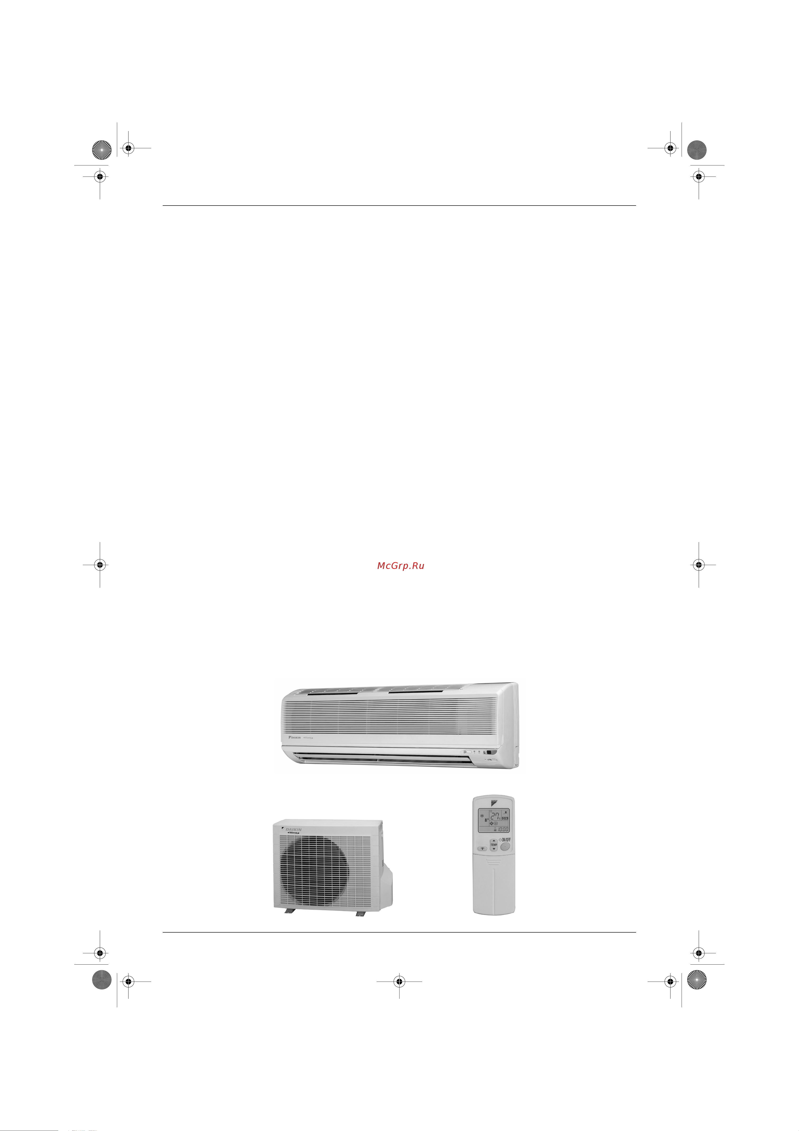
Inverter Pair
FTK(X)-J / RK(X)-J Series
Cooling Only
Indoor Unit
FTK25JV1NB
FTK35JV1NB
Outdoor Unit
RK25JV1NB
RK35JV1NB
Heat Pump
Indoor Unit
FTX25JV1NB
FTX35JV1NB
Outdoor Unit
RX25JV1NB
RX35JV1NB
Si-86.book Page i Friday, June 23, 2000 10:26 AM
Содержание
- Inverter pair ftk x j rk x j series 1
- Caution for diagnosis 2 2
- Code indication on the remote controller 6 2
- Functions 2
- General functionality 0 2
- Instruction 6 2
- Introduction v 2
- Part 1 list of function 2
- Part 2 printed circuit board connector wiring diagram 2
- Part 3 main function 2
- Part 4 system configuration 5 2
- Part 5 service diagnosis 1 2
- Printed circuit board connector wiring diagram and name 2
- Problem symptoms and measures 4 3 service check function 5 2
- Troubleshooting 7 2
- Check 6 3
- For ftk25j ftk35j ftx25j ftx35j 6 3
- For rk25j rk35j rx25j rx35j 03 3
- Others 20 3
- Part 6 removal procedure 5 3
- Part 7 others 19 3
- Part 8 appendix 23 3
- Piping diagram 24 3
- Wiring diagram 27 3
- Drawings flow charts iii 4
- Index i 4
- Introduction 5
- Safety cautions 5
- Warning 5
- Caution 6
- Cautions regarding products after repair 6
- Introduction sie 86 6
- Warning 6
- Caution 7
- Inspection after repair 7
- Sie 86 introduction 7
- Warning 7
- Caution 8
- Introduction sie 86 8
- Using icons 8
- Using icons list 8
- Functions 9
- Indoor unit and outdoor unit 2 9
- Part 1 list of function 9
- Functions 10
- Functions sie 86 10
- Indoor unit and outdoor unit 10
- List of function 10
- Part 2 printed circuit board connector wiring diagram 11
- Printed circuit board connector wiring diagram and name 11
- Control pcb 1 12
- Ftk25 35j series ftx25 35j series 12
- Name of connector 12
- Printed circuit board connector wiring diagram 12
- Printed circuit board connector wiring diagram and name 12
- Printed circuit board connector wiring diagram and name sie 86 12
- Fu s70 v1 14
- L live 14
- N neutral 14
- Name of connector 14
- Printed circuit board connector wiring diagram 14
- Printed circuit board connector wiring diagram and name sie 86 14
- Rk25 35j series rx25 35j series 14
- S signal 14
- S40 s80 s91 14
- Service monitor 14
- General functionality 0 17
- Part 3 main function 17
- Frequency control 18
- Functions of thermistors 18
- General functionality 18
- General functionality sie 86 18
- Location of thermistors 18
- Main function 18
- Frequency controlled functions 19
- Main function 11 19
- Sie 86 general functionality 19
- The following table shows the different functions which are controlled by decreasing or increasing the frequency 19
- General functionality sie 86 20
- Main function 20
- Note the outdoor unit retains the operating mode when the thermostat is switched off 20
- Operating modes 20
- Overview 20
- Refer to pre heat operation on page 21 20
- The following table shows the different control modes of the split inverter room air conditioners 20
- There are two operating modes normal operating mode forced operating mode 20
- Additional control parameters 21
- Drawing of inverter 21
- Frequency principle 21
- Inverter principle 21
- Main control parameters 21
- Main function 13 21
- Sie 86 general functionality 21
- The compressor is frequency controlled during normal operation the target frequency is set by the following 2 parameters coming from the operating indoor unit the load condition of the operating indoor unit the difference between the room temperature and the set temperature 21
- The following drawing shows a schematic view of the inverter principle 21
- The target frequency is adapted by additional parameters in the following cases frequency limits initial settings forced cooling heating operation 21
- To regulate the capacity a frequency control is needed the inverter makes it possible to vary the rotation speed of the compressor the following table explains the conversion principle 21
- Even during extreme cold weather the high capacity is achieved it is maintained even when the outside temperature is 0 c comfortable air conditioning a detailed adjustment is integrated to ensure a fixed room temperature it is possible to air condition with a small room temperature variation energy saving heating and cooling once the set temperature is reached the energy saving operation enables to maintain the room temperature at low power 22
- For more information refer to forced mode on page 16 22
- Forced cooling heating operation 22
- Frequency limits 22
- General functionality sie 86 22
- Inverter features 22
- Main function 22
- The following table shows the functions that define the minimum and maximum frequency 22
- The inverter provides the following features the regulating capacity can be changed according to the changes in the outside temperature and cooling heating load quick heating and quick cooling the compressor rotational speed is increased when starting the heating or cooling this enables a quick set temperature 22
- Conditions 23
- Defrost control 23
- Defrost control is carried out by reversing the cycle from heating to cooling 23
- Defrost control is reset by the following conditions 23
- Defrost control is set by the following conditions during heating more than 6 minutes after the compressor has started up when condition 1 or 2 in the table below are applicable 23
- If 3 c 23
- Main function 15 23
- Principle 23
- Sie 86 general functionality 23
- Start conditions 23
- Stop conditions 23
- The following table shows the different conditions on which defrost control is based 23
- A way to enter the test operation mode by a remote controller 24
- Forced mode 24
- Forced operation mode 24
- General functionality sie 86 24
- H type 24
- J type 24
- Main function 24
- Set on the desirous mode and push on off button operation on 2 two buttons center of temperature set buttons and mode button should be pushed simultaneously then a left figure of the liquid crystal temperature s display number starts to blink 3 moreover push mode button twice if the liquid crystal display becomes the test operation mode will startup under the mode displayed in a liquid crystal 24
- The following table explains the different forced operation modes forced cooling and forced heating 24
- The protective functions overrule the forced mode h type only 24
- H type 25
- Wide angle flaps diffuser louvres and autoswing 25
- Although the liquid crystal display of the five step directions of the air flow is common for the modes of cooling dry heating as illustrated above in fact the range of the swing angle is slightly different in every operation mode the position a user set will be selected among the five positions calculated through the preliminary and evenly divided into four partitions which were taken from the upper and lower flap angle s range limits of each mode when auto swing is chosen the flap swings in the swing range which meets the operation mode selected 26
- Fan mode is available for the models of cooling only 26
- General functionality sie 86 26
- It can be commanded for j type by means of a user setting to select either any one desired position among the five step directions of air flow adjusted on a remote controller or auto swing 26
- J type 26
- Main function 26
- Others 26
- Outline of the action 26
- The vertical louver can be adjusted manually the movable range is 60 degrees for left or right and total 120 degrees a diffuser is not available for j type 26
- Automatic air flow control for cooling 27
- Automatic air flow control for heating 27
- Control mode 27
- Fan speed control for indoor units 27
- For more information about hall ic refer to hall ic check a6 on page 61 27
- Hh powerful 27
- J type 800 980 rpm during powerful operation 1050 rpm 27
- Ll cooling thermostat off 27
- Lll heating thermostat off h type 500 860 rpm during powerful operation 850 910 rpm 27
- Main function 19 27
- Note 1 during powerful operation fan operate h tap 50 70 rpm 2 fan stops during defrost operation 27
- Note when there is no operation and the night set mode turns on the step is low refer to night set mode on page 22 27
- Phase control and fan speed control contains 8 steps lll ll l ml m hm h and hh 27
- Phase steps 27
- Refer to automatic airflow rate control on page 19 27
- Sie 86 general functionality 27
- Step cooling heating dry mode 27
- The airflow rate can be automatically controlled depending on the difference between the set temperature and the room temperature this is done through phase control and hall ic control 27
- The following drawing explains the principle for fan speed control for heating 27
- The following drawing explains the principle of fan speed control for cooling 27
- Within this range the airflow rate is automatically controlled when the airflow adjusting button is set to automatic 27
- C the outdoor fan stays running at the same speed for 28
- Caution j type operates the outdoor unit fans in the cooling mode even at the condition that a compressor is not operated in case of existing model h series the outdoor unit fans stops at the condition that a compressor is not operated 28
- Control 28
- Fan off delay 28
- Fan speed control for outdoor units 28
- General functionality sie 86 28
- Main function 28
- Seconds 28
- The following drawing explains the fan speed control 28
- When the compressor turns off and 28
- 1 decision of the dry setting temperature when entering the following dry mode 1 stop an operation will start with dry 2 mode except dry changing to dry mode thermostat on off point is decided in accordance with the following conditions 29
- 11 c the compressor is warmed up by passing a single phase u v phase current through the compressor motor to speed up the start the power consumption is 30 40w 29
- C room temp 24 c room temp at the entering room temp 1 c at the entering 29
- C room temp room temp at the entering room temp 2 c at the entering 29
- Dry mode 29
- During defrosting or when the thermostat is on in heating mode the indoor heat exchanger temperature 29 c to fan starts to avoid cold draft 29
- For both h j type 29
- Frequency command the frequency command is decided based on a room temperature zone the room temperature zone is decided as follows 29
- General functions 29
- Hot start function 29
- Main function 21 29
- Pre heat operation 29
- Room temp 18 c 18 c 17 c 29
- Room temp cond at entering dry set temp thermostat on thermostat off temp 29
- Sie 86 general functionality 29
- The dry mode removes humidity while maintaining the room temperature the temperature and fan cannot be regulated during dry mode 29
- When the equipment has stopped and 29
- For both h j type 30
- General functionality sie 86 30
- Main function 30
- Night set mode 30
- Required fan speed fan speed changes the rotation speed every time when a thermostat switches over on and off when the thermostat becomes off fan continues to operate 10 minutes more with low speed so as to prevent recovery of humidity caused by reevaporation of the drain water and then stops 30
- The frequency command for every zone is stated below please note that an operation will not carry out in the commanded frequency sometimes in case a protection control like a freeze protection etc will be actuated 30
- The night set mode is activated when the off timer is set it restricts the operation frequency to minimize the noise 30
- Detection method by human motion sensor 31
- Intelligent eye j type 31
- Main function 23 31
- Outline 31
- Processing 31
- Sie 86 general functionality 31
- Since the set temperature is shifted by 2 c higher for 40 minutes compressor speed becomes low and can realize energy saving operation but as thermostat is prone to be off by the fact that the set temperature has been shifted the thermostat off action is prohibited in 40 minutes so as to prevent this phenomena after this 40 minutes the prohibition of the thermostat off is cancelled and it can realize the conditions to conduct thermostat off depending on the room temperature in or after this forty minutes if the sensor detects human motion detection signal it turns on human detection led and let the set temperature and the fan speed return to the original set point keeping a normal operation 31
- The function that detects existence of humans in the air conditioned room and reduces the capacity when no humans are available in the room in order to save electricity by means of a human motion sensor 31
- The motions for example in cooling 31
- This sensor detects human motion by receiving infrared rays and displays the pulse wave output a micro computer in an indoor unit carries out a sampling every 20 msec and if it detects 10 cycles of the wave in one second in total corresponding to 20msec 10 100msec it judges human is in the room as the motion signal is on 31
- When a micro computer doesn t have a signal from the sensor in 20 minutes it judges that no body is in the room and turns off the human detection led operating the unit in temperature sifted 2 c from the set temperature cooling 2 c higher dry 1 c higher and auto according to the operation mode at that time 1 in case of fan mode the fan speed reduces by 50 rpm 31
- Good sleep cooling control j type 33
- Main function 25 33
- Notes 1 each timer s counting stop is not related to a thermostat on off 2 when the sleeping control works by the off timer the shift from the set temperature should be just 1 c with this control function the temperature shift of the normal off timer will not be carried out however the passed time should be remembered since the off timer was set 3 while operation with the good sleep cooling control and off timer setting if the signal of the good sleep cooling off signal comes the level of the set temperature shift should be set corresponding to the same with an existing value in accordance with the passed time since the off timer was set 4 when the good sleep cooling control is on while a normal operation with a off timer is going on once returning to the original criterion which doesn t shift the timer s set temperature and the shift alteration at every sequence by 1 c is carried out in accordance with the value above mentioned 5 fan speed will change by the alteration of the set temp 33
- Outline 33
- Processing 33
- Sie 86 general functionality 33
- The function to create deep sleeping and to offer good sleep by altering the set tempeatures in certain intervals to give temperature variation to a living space based on 1 f temperature fluctuation principle in case of going to bed while air conditioner keeps operating in cooling mode 33
- Automatic operation 34
- Detailed explanation of the function 34
- General functionality sie 86 34
- Main function 34
- With compressor capacity supplied with no compressor capacity supplied 34
- Input current control h j type 35
- Main function 27 35
- Outline 35
- Processing 35
- Sie 86 general functionality 35
- Dto freeze protection temperature of heat exchanger 36
- During cooling dry operation when the heat exchanger s temperature falls down excessively the capacity supply will be reduced frequency step down so as to prevent freeze of the heat exchanger and the creation of dew on a rotor caused by a excessive capacity supply to the indoor unit 36
- Freeze protection function in cooling h j type 36
- General functionality sie 86 36
- Main function 36
- Outline 36
- Processing 36
- The restriction for frequency is not conducted in the return area by means of freeze protection control frequency is increased approximately every 2 hz min in the up area frequency alteration in the steady area is not conducted frequency down is carried out in the step down area approximately every 2 4 hz min compressors stop in the stop area after compressor stops fan keeps operating in 700 rpm for h type and 800 rpm for j type ll operation aiming at rising heat exchanger s temperature 36
- Main function 29 37
- Outline 37
- Peak cut control function h j type 37
- Processing 37
- Sie 86 general functionality 37
- Four way valve function compensation h j type 38
- General functionality sie 86 38
- Main function 38
- Outline 38
- Processing 38
- Compressor protection function h j type 39
- Main function 31 39
- Outline 39
- Processing 39
- Sie 86 general functionality 39
- General functionality sie 86 40
- Main function 40
- Outline 40
- Processing 40
- Wet operation protection h j type 40
- Dew condensation sweating prevention function h j type 41
- Main function 33 41
- Outline 41
- Processing 41
- Sie 86 general functionality 41
- Ftk25 35j ftx25 35j 36 43
- Instruction 6 43
- Part 4 system configuration 43
- Caution 44
- Ftk25 35j ftx25 35j 44
- Instruction 44
- Safety precautions 44
- Warning 44
- Air inlet 45
- Air outlet louvre vertical blades 45
- Air purifying filter front grille 45
- Caution 45
- Flap horizontal blade 45
- Grille tab 45
- Indoor unit 45
- Intelligent eye lamp green operation lamp green 45
- Names of parts 45
- On off button 45
- Opening the front grille 45
- Timer lamp orange 45
- Names of parts 46
- Open the cover 46
- Outdoor unit 46
- Remote controller 46
- Sensor 46
- Attention 47
- Position and correctly 47
- Preparation before operation 47
- Receiver 47
- Remote controller 47
- Remote controller holder set 47
- Sie 86 instruction 47
- System configuration 39 47
- Indoor unit 48
- N setting the air purifying filters 48
- N setting the clock 48
- N turn the breaker on 48
- Preparation before operation 48
- Auto dry cool heat fan operation 49
- On off 49
- Then operation lamp goes off 49
- N to cancel powerful operation 50
- Notes on powerful operation 50
- Powerful operation 50
- Adjusting the air flow direction 51
- Adjusting the horizontal blade flap 51
- Adjusting the louvre 51
- Attention 51
- Notes on flap angles 51
- Sie 86 instruction 51
- System configuration 43 51
- You can adjust the air flow direction to increase your comfort 51
- Attention 52
- Example 52
- Instruction sie 86 52
- N to cancel the timer 52
- Off timer operation 52
- On off 52
- On timer operation 52
- System configuration 52
- Then the timer lamp goes off 52
- Then the timer lamp lights up 52
- Timer functions are useful for automatically switching the air conditioner on or off at night or in the morning you can also use off timer and on timer in combination 52
- Timer operation 52
- Good sleep cooling operation g sleep 53
- N to cancel the good sleep cooling operation press 53
- N to change the air flow direction setting 53
- N to change the air flow rate setting 53
- N to change the temperature setting 53
- Notes on good sleep cooling operation 53
- What is 1 f fluctuation 53
- Caution 54
- Intelligent eye 54
- Intelligent eye is useful for 54
- Notes on intelligent eye 54
- Care and cleaning 55
- Cleaning the air filters 55
- Cleaning the indoor and outdoor units and the remote controller 55
- Replacing air purifying filters 55
- Care and cleaning 56
- Cleaning the front grille 56
- Explanation 57
- L these cases are not troubles 57
- The following cases are not air conditioner troubles but have some reasons you may just continue using it 57
- Trouble s hooting 57
- L check again 58
- Please check again before calling a repair person 58
- Trouble s hooting 58
- Caution for diagnosis 2 59
- Check 6 59
- Code indication on the remote controller 6 59
- Part 5 service diagnosis 59
- Problem symptoms and measures 4 3 service check function 5 59
- Troubleshooting 7 59
- Caution for diagnosis 60
- Indicator lamps 60
- On off 60
- Troubleshooting with the operation lamp 60
- Service diagnosis 53 61
- Sie 86 caution for diagnosis 61
- Troubleshooting with the led indication 61
- Problem symptoms and measures 62
- Problem symptoms and measures sie 86 62
- Service diagnosis 62
- Arc423 series 63
- In the arc423a series the temperature display sections on the main unit indicate corresponding codes 1 when the timer cancel button is held down for 5 seconds a 00 indication flashes on the temperature display section 63
- Note 1 a short beep and two consecutive beeps indicate non corresponding codes 2 to cancel the code display hold the timer cancel button down for 5 seconds the code display also cancels itself if the button is not pressed for 1 minute 63
- Press the timer cancel button repeatedly until a continuous beep is produced the code indication changes in the sequence shown below and notifies with along beep 63
- Service check function 63
- Service diagnosis 55 63
- Sie 86 service check function 63
- Code indication on the remote controller 64
- Code indication on the remote controller sie 86 64
- Error codes and description of fault 64
- Service diagnosis 64
- Indoor units 65
- Not used for troubleshooting varies depending on the cases 65
- Service diagnosis 57 65
- Sie 86 troubleshooting 65
- Troubleshooting 65
- 3 3 3 3 66
- 3 3 3 4 66
- 3 3 4 3 66
- 3 3 4 4 66
- 3 4 3 4 66
- 3 4 4 3 66
- 4 3 4 3 66
- 4 3 4 4 66
- 4 4 3 3 66
- Blinks 66
- Green flashes when in normal condition red off in normal condition not used for troubleshooting varies depending on the cases 66
- Note 1 the indications in the parenthesis in the remote controller display column are displayed only when system down occurs 2 when a sensor error occurs check the remote controller display to determine which sensor is malfunctioning if the remote controller does not indicate the error type conduct the following operation turn the power switch off and back on again if the same led indication appears again immediately after the power is turned on the fault is in the thermistor if the above condition does not result the fault is in the ct 3 the indoor unit error indication may take the precedence in the remote controller display 66
- Outdoor units 66
- Service diagnosis 66
- Troubleshooting sie 86 66
- Aaaa1111 67
- Faulty pcb 67
- Aaaa5555 68
- High pressure control during heating operations the temperature detected by the indoor heat exchanger thermistor is above 67 c freeze protection when the indoor unit heat exchanger temperature is below 0 c during cooling operation 68
- High pressure control during heating operations the temperature detected by the indoor heat exchanger thermistor is used for the high pressure control stop outdoor fan stop etc the freeze protection control operation halt is activated during cooling operation according to the temperature detected by the indoor unit heat exchanger thermistor 68
- Indoor unit led display 68
- Malfunction decision conditions 68
- Method of malfunction detection 68
- Operation halt due to clogged air filter of the indoor unit operation halt due to dust accumulation on the indoor unit heat exchanger operation halt due to short circuit detection error due to faulty indoor unit heat exchanger thermistor detection error due to faulty indoor unit pcb 68
- Operation shutdown due to high pressure control or freeze up protection thermistor activation 68
- Remote controller display 68
- Service diagnosis 68
- Supposed causes 68
- Troubleshooting 68
- Troubleshooting sie 86 68
- Aaaa6666 69
- Check no 6 rerer to p 3 69
- Indoor unit led display 69
- Malfunction decision conditions 69
- Method of malfunction detection 69
- Operation halt due to fan motor ac motor or related abnormality 69
- Operation halt due to short circuit inside the fan motor winding operation halt due to breaking of wire inside the fan motor operation halt due to breaking of the fan motor lead wires operation halt due to faulty capacitor of the fan motor detection error due to faulty indoor unit pcb 1 69
- Remote controller display 69
- Service diagnosis 61 69
- Sie 86 troubleshooting 69
- Supposed causes 69
- The rotation speed detected by the hall ic during fan motor operation is used to determine abnormal fan motor operation 69
- Troubleshooting 69
- When the detected rotation speed is less than 50 of the hh tap under maximum fan motor rotation demand 69
- Cccc4444 cccc9999 ccccaaaa 70
- Indoor unit led display 70
- Malfunction decision conditions 70
- Method of malfunction detection 70
- Operation halt due to detection of thermistor or related abnormality 70
- Remote controller display 70
- Service diagnosis 70
- Supposed causes 70
- Troubleshooting 70
- Troubleshooting sie 86 70
- Faulty indoor unit pcb 71
- Indoor unit led display 71
- Malfunction decision conditions 71
- Method of malfunction detection 71
- Microcomputer program is in abnormal condition due to an external factor noise momentary voltage drop momentary power failure etc faulty indoor unit pcb 71
- Remote controller display 71
- Service diagnosis 63 71
- Sie 86 troubleshooting 71
- Supposed causes 71
- The proper program operation of the microcomputer is checked by the program 71
- Troubleshooting 71
- When the microcomputer program does not function properly 71
- Faulty indoor unit pcb 72
- Display disabled by fault power supply faulty signal transmitting receiving circuit in indoor printed circuit boards 1 and 2 microcomputer program is in abnormal condition due to an external factor noise momentary voltage drop momentary power failure etc faulty indoor unit pcbs 1 and 2 73
- Indoor unit led display 73
- Malfunction decision conditions 73
- Method of malfunction detection 73
- Power supply abnormalities or faulty indoor printed circuit boards 73
- Remote controller display 73
- Service diagnosis 65 73
- Sie 86 troubleshooting 73
- Supposed causes 73
- The proper program operation of the microcomputer is checked by the program 2 in indoor outdoor signal communications the indoor unit determines whether the outdoor unit receives signals properly by detecting signals transmitted by the outdoor unit to the indoor unit 73
- Troubleshooting 73
- Uuuu4444 73
- When the microcomputer program does not function properly 2 when the indoor unit determines that the indoor unit does not properly receive signals transmitted by the outdoor unit in indoor outdoor signal communications 73
- Check no 3 refer to p 2 74
- Faulty outdoor unit pcb faulty indoor unit pcb indoor unit outdoor unit signal transmission error due to wiring error indoor unit outdoor unit signal transmission error due to disturbed power supply waveform indoor unit outdoor unit signal transmission error due to breaking of wire in the connection wires between the indoor and outdoor units wire no 2 74
- Indoor unit led display 74
- Malfunction decision conditions 74
- Method of malfunction detection 74
- Remote controller display 74
- Service diagnosis 74
- Signal transmission error between indoor and outdoor units 74
- Supposed causes 74
- The data received from the outdoor unit in indoor unit outdoor unit signal transmission is checked whether it is normal 74
- Troubleshooting 74
- Troubleshooting sie 86 74
- Uuuu4444 74
- When the data sent from the outdoor unit cannot be received normally or when the content of the data is abnormal 74
- Hhhh8888 75
- Malfunction decision conditions 75
- Method of malfunction detection 75
- Operation halt due to detection of ct error 75
- Outdoor unit led display 75
- Remote controller display 75
- Service diagnosis 67 75
- Sie 86 troubleshooting 75
- Supposed causes 75
- Troubleshooting 75
- Indoor unit led display 76
- Jjjj3333 jjjj6666 hhhh9999 76
- Malfunction decision conditions 76
- Method of malfunction detection 76
- Operation halt due to thermistor error or disconnection detection 76
- Remote controller display 76
- Service diagnosis 76
- Supposed causes 76
- Troubleshooting 76
- Troubleshooting sie 86 76
- Eeee6666 77
- Indoor unit led display 77
- Malfunction decision conditions 77
- Method of malfunction detection 77
- Operation halt due to compressor startup error 77
- Remote controller display 77
- Service diagnosis 69 77
- Sie 86 troubleshooting 77
- Supposed causes 77
- Troubleshooting 77
- Indoor unit led display 78
- Llll5555 78
- Malfunction decision conditions 78
- Method of malfunction detection 78
- Output overcurrent 78
- Remote controller display 78
- Service diagnosis 78
- Supposed causes 78
- Troubleshooting sie 86 78
- Check no 2 refer to p 1 79
- Check no refer to p 0 79
- Check no refer to p 6 79
- Check no refer to p 8 79
- Erroneous internal wiring can result in output overcurrent in some cases if system stops due to output overcurrent after parts replacement that requires disconnection of wires check wiring carefully 79
- Service diagnosis 71 79
- Sie 86 troubleshooting 79
- Troubleshooting 79
- Faulty outdoor unit pcb 80
- Indoor unit led display 80
- Malfunction decision conditions 80
- Method of malfunction detection 80
- Remote controller display 80
- Service diagnosis 80
- Supposed causes 80
- Troubleshooting 80
- Troubleshooting sie 86 80
- Faulty outdoor unit pcb and transmitting receiving circuit 81
- Indoor unit led display 81
- Malfunction decision conditions 81
- Method of malfunction detection 81
- Remote controller display 81
- Service diagnosis 73 81
- Sie 86 troubleshooting 81
- Supposed causes 81
- Troubleshooting 81
- Eeee8888 82
- Indoor unit led display 82
- Malfunction decision conditions 82
- Method of malfunction detection 82
- Operation halt due to detection of input over current 82
- Remote controller display 82
- Service diagnosis 82
- Supposed causes 82
- Troubleshooting sie 86 82
- Check no 2 refer to p 1 83
- Check no refer to p 0 83
- Check no refer to p 6 83
- Check no refer to p 8 83
- Internal wiring errors can cause an input over current if the equipment stops due to an input over current after the wires are disconnected and connected again for parts replacement etc check for wiring errors 83
- Service diagnosis 75 83
- Sie 86 troubleshooting 83
- Troubleshooting 83
- Check no 84
- Check sie 86 84
- How to check 84
- Power transistor check capacitor voltage check 84
- Service diagnosis 84
- Service diagnosis 77 85
- Sie 86 check 85
- Check no 86
- Check sie 86 86
- Output current measurement 86
- Output voltage measurement 86
- Power transistor output check 86
- Service diagnosis 86
- Check no 87
- For the models whose thermistor is directly equipped on the printed circuit board 87
- Remove the connectors of the thermistors on the pcb and measure the resistance of each thermistor using tester the relationship between normal temperature and resistance is shown in the graph and the table below 87
- Remove the signal receiver and the display printed circuit board disconnect the connector too and then measure ohm by an ohmmeter at the both ends the relation between temperature and resistance is in common with the existing models 87
- Service diagnosis 79 87
- Sie 86 check 87
- Thermistor resistance check 87
- Check no 88
- Check sie 86 88
- Installation condition check 88
- Service diagnosis 88
- 0 0 or 89
- Check no 1 89
- Check no 2 89
- Discharge pressure check 89
- For digital tester 89
- Negative 89
- Normal resistance several 89
- Positive 89
- Rectifier check 89
- Service diagnosis 81 89
- Several 89
- Sie 86 check 89
- Terminal of tester negative terminal 89
- Terminal of tester positive terminal 89
- There are several different terminal position patterns therefore be sure to check the terminal marks 89
- Unacceptable resistance 0 o 89
- Check no 3 90
- Check no 5 90
- Check sie 86 90
- Fig fig 90
- Inverter units compressor refrigerant system check 90
- Measure the power supply waveform between pins 1 and 3 on the terminal board and check the waveform disturbance check to see if the power supply waveform is a sine wave fig check to see if there is waveform disturbance near the zero cross sections circled in fig 90
- Power supply waveforms check 90
- Service diagnosis 90
- Check no 6 91
- Inverter units hall ic check 91
- Service diagnosis 83 91
- Sie 86 check 91
- For ftk25j ftk35j ftx25j ftx35j 6 93
- For rk25j rk35j rx25j rx35j 03 93
- Part 6 removal procedure 93
- For ftk25j ftk35j ftx25j ftx35j 94
- For ftk25j ftk35j ftx25j ftx35j sie 86 94
- Procedure 94
- Removal of air filter 94
- Removal procedure 94
- Removal procedure 87 95
- Sie 86 for ftk25j ftk35j ftx25j ftx35j 95
- For ftk25j ftk35j ftx25j ftx35j sie 86 96
- Procedure 96
- Removal of front grille 96
- Removal procedure 96
- Removal procedure 89 97
- Sie 86 for ftk25j ftk35j ftx25j ftx35j 97
- For ftk25j ftk35j ftx25j ftx35j sie 86 98
- Procedure 98
- Removal of horizontal blade and vertical blade 98
- Removal procedure 98
- Removal procedure 91 99
- Sie 86 for ftk25j ftk35j ftx25j ftx35j 99
- For ftk25j ftk35j ftx25j ftx35j sie 86 100
- Procedure 100
- Removal of switch box pc board and swing motor 100
- Removal procedure 100
- Removal procedure 93 101
- Sie 86 for ftk25j ftk35j ftx25j ftx35j 101
- For ftk25j ftk35j ftx25j ftx35j sie 86 102
- Removal procedure 102
- Disengage the four knobs on the back of the display printed circuit board 103
- Display printed circuit board 103
- Removal procedure 95 103
- Sie 86 for ftk25j ftk35j ftx25j ftx35j 103
- For ftk25j ftk35j ftx25j ftx35j sie 86 104
- Removal procedure 104
- Procedure 105
- Removal of heat exchanger 105
- Removal procedure 97 105
- Sie 86 for ftk25j ftk35j ftx25j ftx35j 105
- For ftk25j ftk35j ftx25j ftx35j sie 86 106
- Removal procedure 106
- Install of drain plug 107
- Procedure 107
- Removal procedure 99 107
- Sie 86 for ftk25j ftk35j ftx25j ftx35j 107
- For ftk25j ftk35j ftx25j ftx35j sie 86 108
- Procedure 108
- Removal of fan rotor and motor 108
- Removal procedure 108
- Loosen the hexagon head set screw on the fan rotor 109
- Removal procedure 101 109
- Remove a screw on the left side panel 109
- Remove the motor and fan rotor 109
- Sie 86 for ftk25j ftk35j ftx25j ftx35j 109
- For ftk25j ftk35j ftx25j ftx35j sie 86 110
- Removal procedure 110
- For rk25j rk35j rx25j rx35j 111
- Procedure 111
- Removal of external casing 111
- Removal procedure 103 111
- Sie 86 for rk25j rk35j rx25j rx35j 111
- For rk25j rk35j rx25j rx35j sie 86 112
- Removal procedure 112
- Procedure 113
- Removal of bellmouth and left side plate 113
- Removal procedure 105 113
- Sie 86 for rk25j rk35j rx25j rx35j 113
- For rk25j rk35j rx25j rx35j sie 86 114
- Procedure 114
- Removal of pc board and switch box 114
- Removal procedure 114
- Removal procedure 107 115
- Sie 86 for rk25j rk35j rx25j rx35j 115
- Disconnect the connector s91 of the thermister 116
- Disconnect the wires from the terminal strip 116
- For rk25j rk35j rx25j rx35j sie 86 116
- Removal procedure 116
- Remove the ground wire 116
- Removal procedure 109 117
- Sie 86 for rk25j rk35j rx25j rx35j 117
- For rk25j rk35j rx25j rx35j sie 86 118
- Removal procedure 118
- Procedure 119
- Removal of propeller fan and fan motor 119
- Removal procedure 111 119
- Sie 86 for rk25j rk35j rx25j rx35j 119
- For rk25j rk35j rx25j rx35j sie 86 120
- Procedure 120
- Removal of compressor noise absorption pad 120
- Removal procedure 120
- Removal procedure 113 121
- Sie 86 for rk25j rk35j rx25j rx35j 121
- For rk25j rk35j rx25j rx35j sie 86 122
- Procedure 122
- Removal of partition plate and reactor 122
- Removal procedure 122
- Removal procedure 115 123
- Sie 86 for rk25j rk35j rx25j rx35j 123
- For rk25j rk35j rx25j rx35j sie 86 124
- Procedure 124
- Removal of four way valve 124
- Removal procedure 124
- Removal procedure 117 125
- Sie 86 for rk25j rk35j rx25j rx35j 125
- For rk25j rk35j rx25j rx35j sie 86 126
- Procedure 126
- Removal of compressor 126
- Removal procedure 126
- Explanation 120 127
- Others 20 127
- Part 7 others 127
- Explanation 128
- For cooling operation in case of low ambient temperature 128
- For heat pump 128
- Others 128
- Others sie 86 128
- Test run from the remote controller for heat pump model only 128
- Centralized control for krc72 krp413a1s 129
- Cut jumper jc on the indoor pc bord 129
- Dry keep change over switch all indoor models for cooling only and heat pump model 129
- Method of operating air conditioners individually when two units are installed in one room for cooling only and heat pump model 129
- Others 121 129
- Sie 86 others 129
- Adjusting the angle of the intelligent eye sensor 130
- Others 130
- Others sie 86 130
- Part 8 appendix 131
- Piping diagram 24 131
- Wiring diagram 27 131
- Cooling only and heat pump 132
- Indoor unit 132
- Piping diagram 132
- Appendix 125 133
- Cooling only 133
- Outdoor unit 133
- Rk25jv1nb 133
- Rk35jv1nb 133
- Sie 86 piping diagram 133
- Appendix 134
- Heat pump 134
- Outdoor unit 134
- Piping diagram sie 86 134
- Rx25jv1nb 134
- Rx35jv1nb 134
- Cooling only 135
- Indoor unit 135
- Wiring diagram 135
- Appendix 136
- Caution 136
- Ftx25jv1nb ftx35jv1nb 136
- Heat pump 136
- Wiring diagram sie 86 136
- Appendix 129 137
- Cooling only 137
- Outdoor unit 137
- Rk25jv1nb rk35jv1nb 137
- Si 86 book page 129 friday june 23 2000 10 26 am 137
- Sie 86 wiring diagram 137
- Appendix 138
- Heat pump 138
- Rx25jv1nb rx35jv1nb 138
- Si 86 book page 130 friday june 23 2000 10 26 am 138
- Wiring diagram sie 86 138
- Symbols 139
- Drawings flow charts 141
Похожие устройства
- Daikin RK35JV1NB Сервис мануал
- Daikin RX25JV1NB Сервис мануал
- Daikin RX35JV1NB Сервис мануал
- Daikin FA71FJV1 Инструкция по эксплуатации
- Daikin FA71FJV1 Технические данные
- Daikin FA71FJV1 Инструкция по монтажу
- Daikin FA100FJV1 Инструкция по эксплуатации
- Daikin FA100FJV1 Технические данные
- Daikin FA100FJV1 Инструкция по монтажу
- Daikin FAY71FJV1 Инструкция по эксплуатации
- Daikin FAY71FJV1 Технические данные
- Daikin FAY71FJV1 Инструкция по монтажу
- Daikin FAY100FJV1 Инструкция по эксплуатации
- Daikin FAY100FJV1 Технические данные
- Daikin FAY100FJV1 Инструкция по монтажу
- Daikin FAYP71BV1 Инструкция по монтажу
- Daikin FAYP71BV1 Технические данные
- Daikin FAYP71BV1 Сервис мануал
- Daikin FAYP100BV1 Инструкция по монтажу
- Daikin FAYP100BV1 Технические данные