
Pioneer DVH-P4100UB Инструкция по установке онлайн
Содержание
- A oo ooo ооо 1
- Dvd rds receiver dvd rds ресивер 1
- Dvh p4100ub 1
- Installation manual 1
- Руководство по установке 1
- Рюпеег 1
- Connecting and installing the optical cable connection box 2
- Connecting the optical cable 2
- Connecting to separately sold power amp when connecting with a multi channel processor 2
- Connection box 2
- Installing the optical cable 2
- Ooo oo o 3
- Din front mount 4
- Din front rear mount 4
- Din rear mount 4
- Installation with the rubber bush 4
- Removing the unit 4
- Оо ооо ооо 5
- Примечание 5
- Соединения силовых кабелей 5
- Монтаж соединительной коробки оптического кабеля 6
- Подсоединение и монтаж соединительной коробки оптического кабеля 6
- Соединение оптического кабеля 6
- Соединение с усилителем мощности который продается отдельно подключение многоканального процессора 6
- Когда используется экран подключенный к видеовыходам_______ 7
- Когда соединяете с наружным видео компонентом_______________ 7
- Заднее крепление по стандарту din 8
- Переднее заднее крепление по стандарту din 8
- Переднее крепление по стандарту din 8
- Примечание 8
- Удаление устройства 8
- Установка с резиновой втулкой 8
Похожие устройства
- Pioneer DVH-P4100UB Руководство пользователя
- Pioneer DVH-P4100UB Краткое руководство
- Pioneer DVH-P5000UB Инструкция по установке
- Pioneer DVH-P5000UB Руководство пользователя
- Pioneer DVH-P5900MP Руководство пользователя
- Pioneer DVH-P5900MP Инструкция по установке
- Sharp QT-222WR(S) Руководство пользователя
- Pioneer DVH-P7000R Инструкция по установке
- Pioneer DVH-P7000R Руководство пользователя
- Sharp QT-222WR(BK) Руководство пользователя
- Pioneer AVH-P6500DVD Инструкция по установке
- Pioneer AVH-P6500DVD Руководство пользователя
- Pioneer AVH-P6600DVD Инструкция по установке
- Pioneer AVH-P6600DVD Руководство пользователя
- Garmin GPSMAP 495 Инструкция по эксплуатации
- Garmin GPSMAP 495 Руководство пользователя
- Garmin Oregon 550 Краткое руководство
- Garmin Oregon 550 Инструкция по эксплуатации
- Garmin nuvi 2370LT Краткое руководство
- Garmin nuvi 2370LT Руководство по эксплуатации
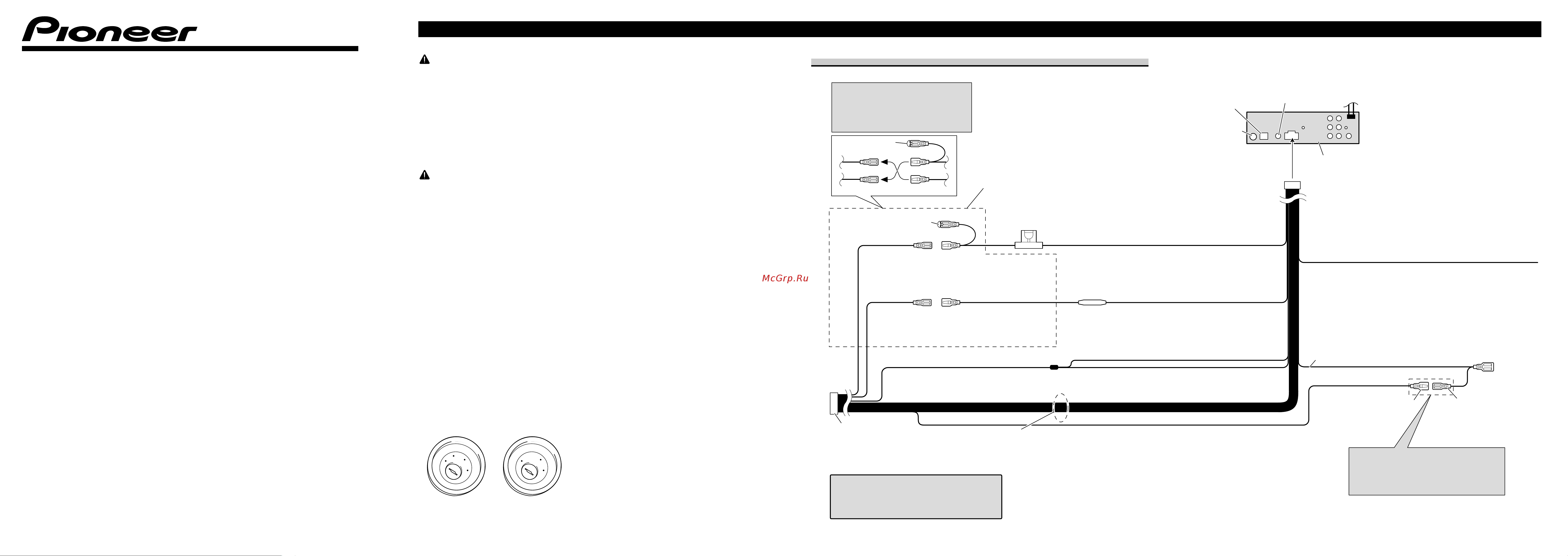
Рюпеег Connecting the Units WARNING To avoid tire risk of accident and the potential vio lation of applicable laws the front DVD or TV sold separately feature should never be used while the vehicle is being driven Also Rear Displays should not be in a location where it is a visible distraction to the driver In some countries or states the viewing of images on a display inside a vehicle even by persons other than the driver may be illegal Where such regula tions apply they must be obeyed and this unit s DVD features should not be used DVD RDS RECEIVER DVD RDS РЕСИВЕР DVH P4100UB CAUTION Installation Manual Руководство по установке PIONEER does not recommend that you install or service your display yourself Installing or servic ing the product may expose you to risk of electric shock or other hazards Refer all installation and servicing of your display to authorized Pioneer ser vice personnel Secure all wiring with cable clamps or adhesive tape Do not allow any bare wiring to remain exposed Do not drill a hole into the engine compartment to connect the yellow lead of the unit to the vehicle battery Engine vibration may eventually cause the insulation to fail at the point where the wire passes from the passenger compartment into the engine compartment Take extra care in securing the wire at this point It is extremely dangerous to allow the display lead to become wound around the steering column or gearshift Be sure to install the display in such a way that it will not obstruct driving Make sure that wires will not interfere with mov ing parts of the vehicle such as the gearshift park ing brake or seat sliding mechanism Do not shorten any leads If you do the protection circuit may fail to work properly Note This unit cannot be installed in a vehicle that does not have an ACC accessory position on the ignition switch ACC position Printed in Thailand CRD4383 A N UW KMINX 08l00000 No ACC position ENGUSH Use this unit in other than the following condi tions could result in fire or malfunction Vehicles with a 12 volt battery and negative grounding Speakers with 50 W output value and 4 ohm to 8 ohm impedance value To prevent short circuit overheating or malfunc tion be sure to follow the directions below Disconnect the negative terminal of the battery before installation Secure the wiring with cable clamps or adhe sive tape To protect the wiring wrap adhesive tape around them where they lie against metal parts Place all cables away from moving parts such as gear shift and seat rails Place all cables away from hot places such as near the heater outlet Do not pass the yellow cable through a hole into the engine compartment to connect to a battery Cover any disconnected cable connectors with insulating tape Do not remove RCA caps if RCA cables are not used Do not shorten any cables Never cut the insulation of the power cable of this unit in order to share the power to other equipment Current capacity of the cable is limited Use a fuse of the rating prescribed Never wire the speaker negative cable directly to ground Never band together multiple speaker s nega tive cables Control signal is output through blue white cable when this unit is powered on Connect it to an external power amp s system remote control or the vehicle s auto antenna relay control terminal max 300 mA 12 V DC If the vehicle is equipped with a glass antenna connect it to the antenna booster power supply terminal Never connect blue white cable to external power amp s power terminal Also never connect it to the power terminal of the auto antenna Otherwise battery drain or malfunction may result IP BUS connectors are color coded Be sure to connect connectors of the same color Black cable is ground This cable and other prod uct s ground cable especially high current prod ucts such as power amp must be wired separate ly Otherwise fire or malfunction may result if they are accidentally detached Power cable connection Note Depending on the kind of vehicle the function of 3 and 5 may be different In this case be sure to connect 2 to 5 and 4 to 3 IP BUS input Blue Antenna jack Wired remote input Hard wired remote control adaptor can be connected sold separately a oo OOo ООО Th is product Connect leads of the same color to each other Capii Do not remove cap if litis terminal is not in use __ Fuse 10 A Yellow 3 Back up or accessory Yellow 2 Connect to the constant 12 V supply terminal Red 5 Accessory or back up Red 4 Connect to terminal controlled by ignition switch 12 V DC Fuse resistor Yellow black If you use an equipment with Mute function wire this lead to the Audio Mute lead on that equipment If not keep the Audio Mute lead free of any connections Blue white Connect to system control terminal of the power amp max 3 X mA 12 V DC Black chassis ground Connect to a clean paint free metal location Blue white 6 ISO connector Note In some vehicles the ISO connector may be divided into two In this case be sure to connect to both connectors When you connect the separately sold multi channel processor DEQ P66 XI to this unit do not connect anything to the speaker leads and system remote control blue white Speaker leads White Front left White black Front left Gray Front right Gray black Front right Green Rear left Green black Rear left Violet Rear right Violet black Rear right Blue white 7 Connect to auto antenna relay control terminal max 300 mA 12 V DC The pin position of the ISO connector will differ depends on the type of vehicle Connect 6 and 7 when Pin 5 is an antenna control type In another type of vehicle never connect 6 and 7