
Daikin KRP2A52 Инструкция по монтажу онлайн
Содержание
Похожие устройства
- Daikin KRP2A53 Инструкция по монтажу
- Daikin REQ71B8V3B Инструкция по монтажу
- Daikin REQ71B2V3B Инструкция по монтажу
- Daikin REQ100B8V3B Инструкция по монтажу
- Daikin REQ71B8W1B Инструкция по монтажу
- Daikin REQ71B2W1B Инструкция по монтажу
- Daikin REQ100B8W1B Инструкция по монтажу
- Daikin REQ125B8W1B Инструкция по монтажу
- Daikin REQ71B7V3B Инструкция по монтажу
- Daikin REQ100B7V3B Инструкция по монтажу
- Foodatlas GK-9-2 Инструкция по эксплуатации
- Foodatlas GK-9-2 Сертификат
- Foodatlas GK-26-1A Инструкция по эксплуатации
- Foodatlas GK-26-1A Сертификат
- Foodatlas GK-9-2+Нитки мешкозашивочные 1000м (ИНД) Инструкция по эксплуатации
- Foodatlas GK-9-2+Нитки мешкозашивочные 1000м (ИНД) Сертификат
- Foodatlas GK-9-2 Eco Инструкция по эксплуатации
- Foodatlas GK-9-2 Eco Сертификат
- Foodatlas GK-26-2A (две нити) Инструкция по эксплуатации
- Foodatlas GK-26-2A (две нити) Сертификат
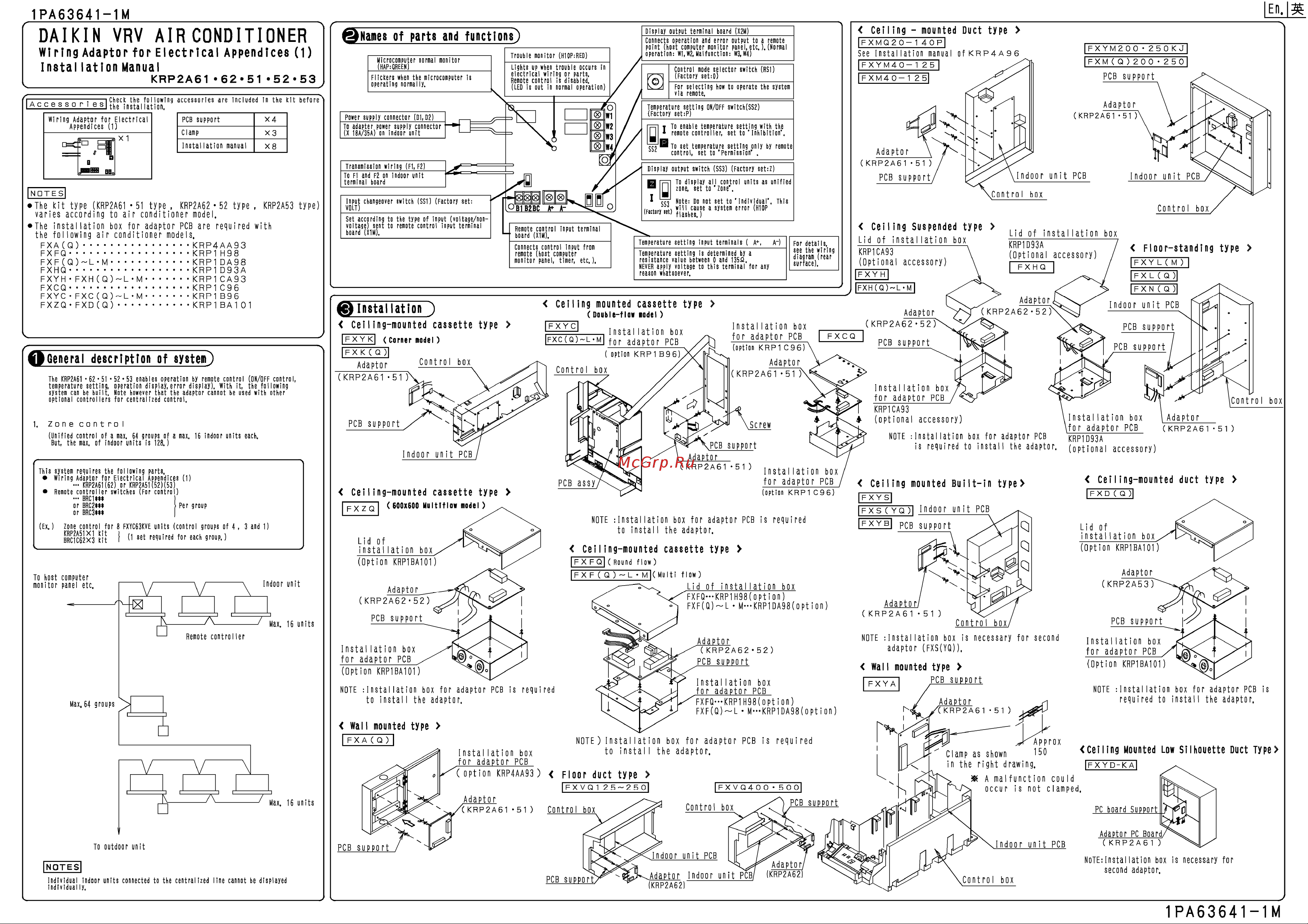
EU 1PA63641 1M Microcomputer normal monitor HAP GREEN _ _ _ _ _ _ _ _ _ _ _ _ _ _ _ _ Flickers when the microcomputer is operating normally Trouble monitor H1OP RED Lights up when trouble occurs in electrical wiring or parts Remote control is disabled LED is out in normal operation 0 mBlo set temperature setting only by remote control set to Permission I ccq Note Do not set to Individual This F ct n irt 1 Control box I 1 Celling Suspended type Remote control input terminal board X1M Temperature setting input terminals A Ai Temperature setting is determined by a resistance value between 0 and 1352 NEVER apply voltage to this terminal for any reason whatsoever For details see the wiring diagram rear surface Installation Installation box for adaptor PCB FXCQ option KRP1 C96 option KRP1 B96 BRC C62X3 kit I 1 set required for each group PCB support PCB support PCB support NOTE Installation box for adaptor PCB to instal I the adaptor Lid Of instal lation box Option KRP1BA101 is required Ceiling mounted Built in ty pe KRP2A61 51 Ceiling mounted duct type FX YS F X S Y Q T IndOOr Unit PCB lFXYBI PCB support Q Q Ceiling mounted cassette type Lid Of instal lation box Option KRP1BA101 FX FQ Round flow Adaptor flow FX F Q L M Multi KRP2A53 Lid of installation box FXFQ KRP1H98 0pt i 00 FXF Q L M KRP1 DA98 0Pt i on Adaptor KRP2A62 52 Adaptor KRP2A61 51 PCB support Control box NOTE instal lation box is necessary for second Adaptor Installation box for adaptor PCB Option KRP1BA101 NOTE I nsta 11 at ï on box to instalI the adaptor Control box Instal lation box for adaptor PCB KRP1D93A optional accessory Installation box for adaptor PCB option KRP1 C96 PCB assy 1 To host computer monitor panel etc KRP2A62 52 Adaptor FXZQ 600x600 Multiflaw model and Indoor unit PCB KRP2A62 52 NOTE Installation box for adaptor PCB is required to instalI the adaptor PCB support Ceiling mounted cassette type 3 F X Y L MT FXN Q Installation box for adaptor PCB KRP1CA93 optional accessory KRP2A61 51 4 Floor standing KRP2A61 51 f Indoor unit PCB of box Adaptor Control box KRP2A61 51 This system requires the following parts Wiring Adaptor for Electrical Appendic s 1 KRP2A6K62 or KRP2A51 52 53 Remote controller switches For contro BRC1 U or BRC2 H or BRC3 groups Adaptor Double flow nodel _ _ _ _ Installation box FXC Q L M fOr adaptor PCB FXYK corner model FX K Q Adaptor Control box control Lid of installation KRP1D93A Optional accessory FXHQ Adaptor PCB support units Lid of installation box KRP1CA93 Optional accessory FXYH Celling mounted cassette type Unified control of a max 64 groups of a max 16 indoor units each But the max of indoor units is 128 FXYC63KVE Indoor unit PCB Control box FXH Q L 1 Zone control 8 Indoor unit PCB PCB support H 1751 To display all control units as unified H zone set to zone Connects control input from remote host computer monitor panel timer etc The KRP2A61 62 51 52 53 enables operation by remote control ON OFF control temperature setting operation display error display With it the following system can be built Note however that the adaptor cannot be used with other optional controllers for centralized control control or Adaptor KRP2A61 51 Display output switch SS3 Factory set Z input changeover switch SS1 Factory set VOLT _ _ _ _ _ _ _ _ _ _ _ _ _ _ _ _ _ _ _ _ _ _ _ _ _ _ Set according to the type of input voltage nonvoitage sent to remote control input terminal board X1M General description of system zone Adaptor KRP2A61 51 T To enable temperature setting with the 1 remote controller set to Inhibition Ceiling mounted cassette type Ex FXYM200 250 K J FXM Q 200 25Ô PCB support Temperature setting ON OFF switch SS2 Factory set P _ _ _ _ _ _ _ _ _ _ _ _ _ _ _ _ _ _ _ _ Transmission wiring F1 F2 TO Fl and F2 on indoor unit terminal board FXA Q KRP4AA93 FXFQ KRP1 H98 FXF Q L M KRP1 DA98 FXHQ KRP1 D93A FXYH FXH Q L M KRP1CA93 FXCQ KRP1 C96 FXYC FXC Q L M KRP1B96 FXZQ FXD Q KRP1 BAI 01 FXMQ20 140P See Installation manual ofKRP4A96 FXYM40 1 25 I FXM40 1 2 5 Control mode selector switch RSI Factory set Q _ _ _ _ _ _ _ _ _ _ _ _ _ _ _ _ _ _ _ _ For selecting how to operate the system via remote Power supply connector DI D2 To adapter power supply connector X 18A 35A on indoor unit NOTES The kit type KRP2A61 51 type KRP2A62 52 type KRP2A53 type varies according to air conditioner model The installation box for adaptor PCB are required with the following air conditioner models Ceiling mounted Duct type Display output terminal board X2M Connects operation and error output to a remote point host computer monitor panel etc Normal operation W1 W2 Malfunction W3 W4 QNamei of parts and functions adaptor FXS YQ KRP2A62 52 PCB support for adaptor PCB Wal I mounted type Installation box for adaptor PCB FXFQ KRP1 H98 Dpt ion FXF Q L M KRP1DA98 0 pt i 0 n is requ i red PCB support Instal lation box for adaptor PCB Option KRP1BA101 PCB support NOTE Installation box for adaptor required to install the adaptor Adaptor KRP2A61 51 wall mounted type FXA Q NOTE installation box Installation box for adaptor PCB option KRP4AA93 to instalI the for adaptor PCB is required adaptor Floor duct type FXVQ1 25 250 FXVQ400 500 Adaptor KRP2A61 51 Clamp as shown in the right drawing A malfunction could occur is not clamped PCB support Control box Control box Ceiling Mounted LOW Silhouette Duct Type FX YD KA PC board Support Adaptor PC Board Indoor unit PCB PCB support ndoor unit PCB NOTES individual indoor units connected to the centralized line cannot be displayed individual ly PCB support Adaptor ndoor unit PCB KRP2A62 Adaptor KRP2A62 KRP2A61 NOTE installation box is necessary for second adaptor Control box PCB is