
Haier HCFU-14H03 Сервис мануал онлайн
HCFU-14H03 (AC142ACAAA+AU142AFAAA)
HCFU-18HC03 (AC182ACABA+AU182AFABA)
HCFU-24H03 (AC242ACAAA+AU242AHAAA)
HCFU-28HC03 (AC282ACABA+AU282AHABA)
HCFU-36H03 (AC36NACAAA+AU36NAIAAA)
HCFU-42HC03 (AC42NACABA+AU42NAIAEA)
MANUAL CODE: SYJS-006 EDITION:2002.12.31.
Haier Group
Auto-restart function
Group control(with a group controller)
Auto-changeover
Compact design of indoor unit
Weekly timing(with a weekly timer)
Features
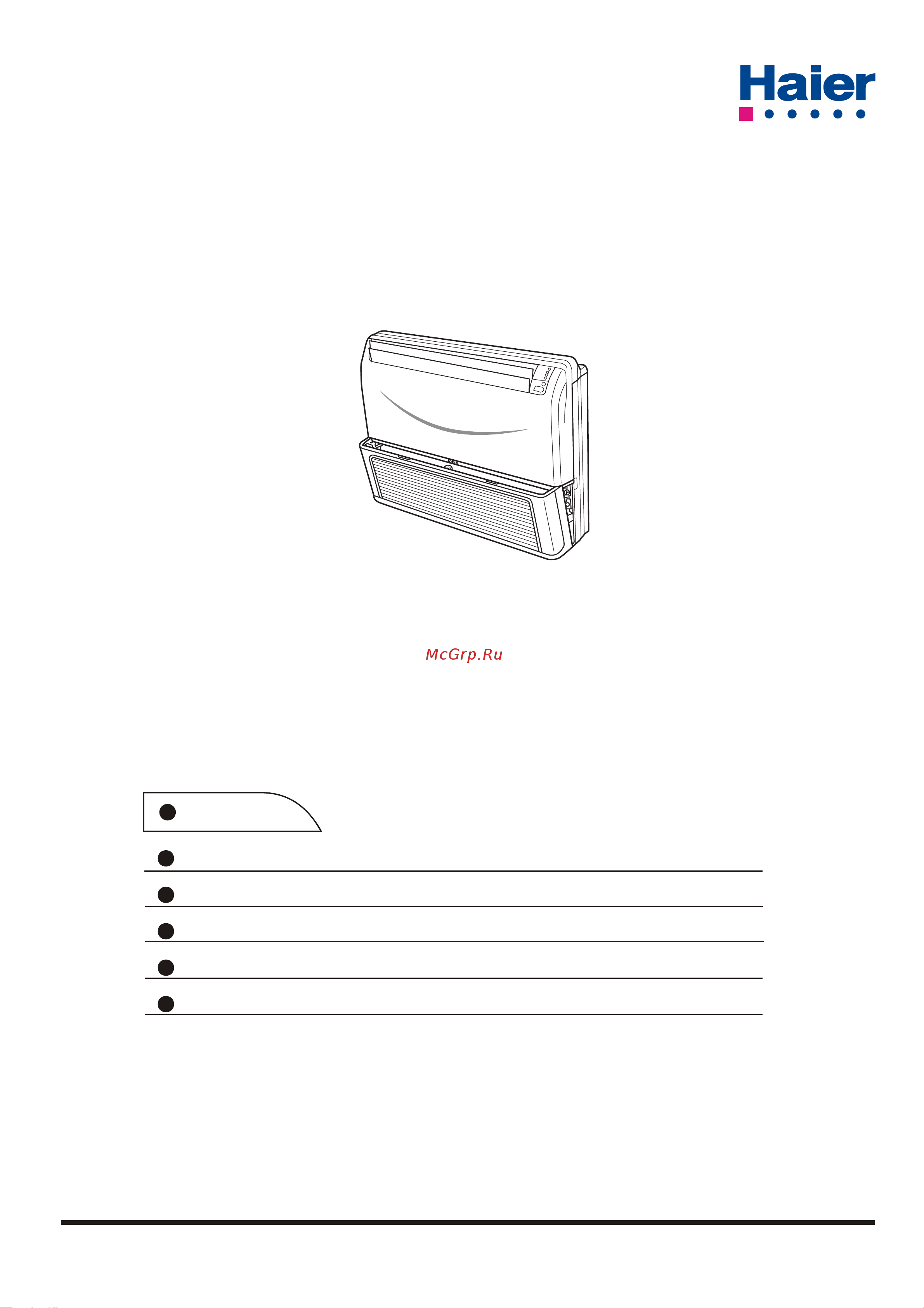
Service Manual
Commercial Air Conditioning
Convertible Type R22 Heat Pump Series
Содержание
- C onvertible type r22 heat pump series 1
- Commercial air conditioning 1
- Features 1
- Haier group 1
- Service manual 1
- Brief introduction to t1 3
- Description of products features 3
- Operating range of a ir c onditioners 3
- Products coding direction 3
- T3 working condition 3
- Description of products features 4
- Products characteristic 4
- Specifications 5
- Specifications 6
- Specifications 7
- Specifications 8
- Specifications 9
- Specifications 10
- Safety precautions 11
- Warning 11
- Caution 12
- Safety precautions 12
- Warning 12
- Model hcfu 14h03 hcfu 18hc03 indoor unit 13
- Model hcfu 14h03 hcfu 18hc03 outdoor unit 13
- Net dimensions of indoor and outdoor unit 13
- Model hcfu 24h03 hcfu 28hc03 indoor unit 14
- Net dimensions of indoor and outdoor unit 14
- Installation servicing space at least 15
- Model hcfu 24h03 hcfu 28hc03 outdoor unit 15
- Net dimensions of indoor and outdoor unit 15
- Note 1 fix the parts with screws 2 don t intake the strong wind directly to the outlet air flow hole 3 a one meter distance should be kept from the unit top 4 don t block the surroudings of the unit with sundries 15
- Power wiring distribution hole 15
- Power wiring terminal 15
- Screw hole m10 15
- Unit mm 15
- Model hcfu 36h03 hcfu 42hc03 indoor unit 16
- Net dimensions of indoor and outdoor unit 16
- Installation servicing space at least 17
- Model hcfu 36h03 hcfu 42hc03 outdoor unit 17
- Net dimensions of indoor and outdoor unit 17
- Note 1 fix the parts with screws 2 don t intake the strong wind directly to the outlet air flow hole 3 a one meter distance should be kept from the unit top 4 don t block the surroundings of the unit with sundries 17
- Power wiring terminal 17
- Screw hole m10 17
- Unit mm 17
- For authorized service personnel only 18
- Installation instructions 18
- Warning 18
- Installation instructions 19
- Accessories 20
- Installation instructions 20
- Mark parts name 20
- Standard parts 20
- Connection pipe requirement 21
- Drain hose left side drain hose right side 21
- For series 24 28 36 42 not the power plug but 3 core connecting cable 21
- Install the room air conditioner as follows 21
- Installation instructions 21
- Installation procedure 21
- Installing drain hose 21
- Intake grill 21
- Machine screw tapping screw 21
- Open the intake grill and remove the three or four or six screws 21
- Preparing indoor unit installation 21
- Remark the main unit can be wired before the indoor unit is installed select the most appropriate installation order 21
- Remove the intake grill 21
- Select piping and drain directions fig for series 14 18 the piping and drain can be made in three directions as shown below for series 24 28 36 42 can be made rear and down two directions 21
- Tapping screw 21
- The drain hose can be connected to either the left or right side fig for series 24 28 36 42 only right side 21
- When the directions are selected drill a 7 cm dia hole on the wall so that the hole is tilted downward toward the outdoor for smooth water flow when the pipe is led out from the rear make a hole in fig at the position shown 21
- 28 36 42 1920 1840 1240 1320 22
- A b 40 40 22
- B under ceiling type 22
- Caution 22
- Completely into the anchor bolts with a hammer fig 16 22
- Drilling for piping 22
- Drilling holes for anchor bolts and installing the anchor bolts 22
- Drilling position for anchor bolt 22
- Drilling position for piping 22
- Fig 12 22
- Fig 13 22
- Fig 18 22
- Fig 19 22
- For series 14 18 22
- Hex bolt 22
- Insert the anchor bolts into the drilled holes and drive the pins 22
- Installation instructions 22
- Installation template 22
- Mm 326mm 247mm 22
- Rear install the drain hose in the direction 22
- Select piping and drain directions for series 24 28 36 42 only rear side fig 3 22
- Series a b 22
- To 13mm indoor unit 22
- To 70mm 22
- Using the installation template drill holes for piping and anchor bolts for holes fig 2 22
- Wall ceilling 22
- Arrange the drain hose lower than this portion 23
- B foundation anchor 23
- Base bottom 23
- Connecting the piping 23
- Drain hose 23
- Extend the pipe by unwinding it 23
- Fig 20 23
- Fig 25 23
- For series 14 18 23
- For series 24 28 36 42 23
- For series 24 28 36 42 no this part 23
- Install the drain hose select whether the drain hose will be connected to the left or right side fig insert the drain hose into the drain pan then secure the drain hose with a nylon fastener fig wrap the insulation drain hose around the drain hose connection fig be sure to arrange the drain hose correctly so that it is leveled lower than the drain hose connecting port of the indoor unit fig 0 23
- Installation instructions 23
- Installation of outdoor unit 23
- Intake grill 23
- L dimension 23
- Liquid pipe 1 to 1 mm 6 5mm dia gas pipe 2 to 2 mm 15 8mm dia gas pipe 3 to 2 mm 19 5mm liquid pipe 1 to 2 mm 9 2mm 23
- Outdoor unit installation 23
- Pass the drain hose through here cut the grill 23
- Piping hole 23
- Remove the hole cover 23
- Selection of the place of installation 23
- Table 1 23
- Vt wire 23
- Vt wire hole 23
- When drain hose is arranged backward secure the drain hose with the vt wire fig 21 23
- Width across flats 23
- 2 piping size 24
- 4 piping connection fig 6 24
- 5 purging mehtod the refrigerant is r407c 24
- A concrete foundation 24
- B foundation anchor 24
- Connecting method apply refrigerant oil at half union as large and flare nut to bend a pipe give the roundness as possible not to crush the pipe when connecting pipe hold the pipe centre to centre then screw nut on by hand refer to fig be careful not to let foreign matters such as sands enter the pipe 24
- Deep enough 24
- Do not twist or crush piping be sure that no dust is mixed in piping bend piping with as wide angle as possible keep insulating both gas and liquid piping check flare connected area for gas leakage 24
- For series 14 18 for series 24 28 36 42 24
- For series 24 28 24
- For series 36 42 24
- Foundation to fix anchor bolts 24
- Gas side 15 8mm 5 8 24
- Give enough room for the concrete 24
- Indoor unit 24
- Install the removed flare nuts to the pipes to be connected then flare the pipes 24
- Install the unit so that the angle of inclination must be less than 3 degrees 24
- Installation instructions 24
- Liquid side 6 5mm 1 4 24
- Note 1 24
- One way piping length less than 15 mm vertical height difference less than 5 m 24
- Pipe dia fastening torque 24
- Place the concrete foundatio 24
- Refrigerant piping 24
- Vacuum pump 24
- Way valve 24
- Installation instructions 25
- Caution 26
- Gas leakage inspection 26
- How to connect wiring to the terminals 26
- If needing to remove the refrigerant gas when installation or repair please refer to the following procedures 26
- Installation instructions 26
- 1 match the terminal block numbers and connection cord colors with those of the outdoor unit erroneous wiring may cause burning of the electric parts 27
- 1 remove the cord clamp 2 process the end of the connection cords to the dimensions shown in fig 4 3 connect the end of the connection cord fully into the terminal block 27
- 1 remove the electric component box 27
- 2 connect the connection cords firmly to the terminal block imperfect installation may cause a fire 27
- 2 pull out the electric component box 27
- 3 always fasten the outside covering of the connection cord with the cord clamp if the insulator is chafed electric leakage may occur 27
- 3 remove the electric component box cover 27
- 4 always connect the ground wire 27
- 4 fasten the connection cord with a cord clamp 5 fasten the end of the connection cord with the screw 6 for series 24 28 36 42 the power cable and connecting are self provided 27
- 4 wiring 27
- Be careful not to pinch the lead wires between the electric component box and base 27
- Caution 27
- Do not remove the screws if the screws are removed the electric component box will fall 27
- Electric component box 27
- Fig 32 27
- Fig 33 27
- For series 14 28 27
- For series 36 42 27
- Installation instructions 27
- Remove the four tapping screws 27
- 1 indoor unit 28
- 2 outdoor unit 28
- Customer guidance 28
- Installation instructions 28
- Mount the cover plate and the intake grill 28
- Mount the cover plate left 28
- Mount the intake grill 28
- Test running 28
- Warning 28
- Drawings 29
- Fig indoor unit 29
- Fig outdoor unit 29
- For series 14 18 29
- For series 24 28 29
- For series 36 42 29
- Parts and functions 29
- Buttons and display of the remote controller 30
- Introduction to spare parts 30
- Power on off temp 30
- Remote controller functions 30
- Reset lock 30
- Introduction to spare parts 31
- Confirmation indicator 32
- Load the battery 32
- Loading of the battery 32
- Put on the cover again 32
- Remote controller functions 32
- Remote controller operation 32
- Remote controller s operation 32
- Remove the battery cover 32
- 1 unit start 33
- 2 select operation mode 33
- 4 unit stop 33
- Fan operation 33
- Guide to operation 33
- Remote controller functions 33
- 1 unit start 34
- 2 select operation mode 34
- 3 select temp setting 34
- Auto run cool heat and dry operation 34
- Guide to operation 34
- Recommendations 34
- Remote controller functions 34
- 4 fan speed selection 35
- 5 air flow direction adjust 35
- 6 unit stop 35
- Guide to operation 35
- Remote controller functions 35
- Guide to operation 36
- Timer on off 36
- Timer operation 36
- To cancel timer mode 36
- 1 after unit start select your desired operation mode 37
- 2 press timer button to change timer mode 37
- 3 time setting for timer on 37
- 4 time confirming for timer on 37
- 5 time confirming for timer off 37
- 6 time setting for timer off 37
- Guide to operation 37
- Remote controller functions 37
- Timer on off 37
- To cancel timer mode 37
- Adjusting up down air flow direction 38
- Air flow direction adjustment procedure 38
- Caution 38
- Remote controller functions 38
- Comfortable sleep 39
- In cooling dehumidifying mode 39
- In heating mode 39
- Remote controller functions 39
- Power failure resume to be applied for a necessary situation 40
- Remote contro 40
- Remote controller functions 40
- Dimensions of the controller 41
- Refrigerant diagram 41
- Remote controller functions refrigerant diagram 41
- Blowing 42
- Control features 42
- Cooling 42
- Cooling blowing 42
- Cooling ts 3 42
- Electrical control functions 42
- Heating 42
- Room temperature rising 42
- Electrical control functions 43
- Area a 44
- Area a ts 44
- Area b 44
- Area c 44
- Electrical control functions 44
- Room temperature falling 44
- Room temperature rising 44
- Electrical control functions 45
- Electrical control functions 46
- And then the fan motor will run in the normal way 47
- By the method of the sensor collects the coil temperature to change the voltage of the outdoor fan motor thus to change the fan speed as a result the system pressure is restricted 47
- Electrical control functions 47
- Introduction to the fan speed controller 47
- Neutral wire 47
- The fan motor runs in the lowest voltage 60v and if the temperature falls continuously to 27 47
- The fan speed will rise according to the line in the above chart until the temperature be 42 47
- The low ambient temperature cooling system realizes starting normally at the temperature 15 47
- The outdoor fan motor starts and runs in the lowest voltage 60v if the condensator temperature can not stop rising when it is 39 47
- The outdoor fan motor stops 47
- The voltage would be the highest value 210v and the fan motor runs in the normal way as the outdoor temperature descends the condensator temperature descends too and the pressure of the compressor discharge lowers the voltage of the fan motor falls along with the coil temperature according to the above chart the coil temperature descends the fan speed descends too when the temperature falls to 39 47
- When the coil temperature exceeds 42 47
- When the fan motor stops the pressure of the compressor discharge rises gradually and also the condensator temperature if the temperature rises to 35 47
- Defrost operation flow chart 48
- Electrical control functions 48
- Or off 48
- Diagnostic information trouble shooting 49
- Fault c odes 49
- Diagnostic information trouble shooting 50
- Trouble checkup result possible reasons corresponding solution 50
- Trouble shooting detailed for engineer 50
- Diagnostic information trouble shooting 51
- Trouble checkup result possible reasons corresponding solution 51
- Diagnostic information trouble shooting 52
- Trouble checkup result possible reasons corresponding solution 52
- Diagnostic information trouble shooting 53
- Trouble checkup result possible reasons corresponding solution 53
- 3 6 3 6 6 1 54
- B r b r w 54
- C o m p 54
- Electrical data 54
- G g r a y 54
- V a l v e 54
- W i r i n g d i a g r a m o f o u t d o o r u n i t 54
- Wiring diagram 54
- Y g b l 54
- Capacitor 55
- Electrical data 55
- Elements line are optional 55
- Hcfu 24h03 hcfu 28hc03 55
- Note the parts inside the broken 55
- Electrical data 57
- Hcfu 14h03 hcfu 18hc03 57
- Electrical data 58
- Hcfu 24h03 hcfu28hc03 hcfu36h03 hcfu42hc03 58
- Outdoor 58
- 3 thermostat chart sensor resistance temperature graph 59
- Electrical data 59
- H cf u 36 h03 h cf u 42 hc03 59
- Electrical data 60
- R t chart of sensor 60
- 1 2 3 4 5 6 7 8 9 10 11 12 13 14 15 16 17 18 19 20 21 22 23 24 25 26 27 28 29 30 31 32 33 34 35 36 37 38 39 40 41 42 43 44 45 46 47 48 49 50 61
- Electrical data 61
- R t chart of sensor r25 61
- Resistance k 61
- Electrical data 62
- R t chart of sensor 62
- Exploded views parts lists 64
- Exploded views parts lists 66
- Exploded views parts lists 68
- Hcfu 14h03 hcfu 18hc03 68
- No name of parts part specialized code qty remark 68
- Exploded views parts lists 70
- Exploded views parts lists 71
- Model hcfu 36h03 hcfu 42hc03 indoor unit 71
- Exploded views parts lists 72
- H cf u 36h03 h cf u 42hc03 part list of indoor unit no name of parts part specialized code qty remark 72
- Exploded views parts lists 73
- Hbu 36h03 hbu 42hc03 outdoor units 73
- Exploded views parts lists 74
- 22 25 27 30 32 75
- 5 5 15 25 35 43 75
- Hcfu 14 h03 hcfu 18hc03 75
- Performance curves 75
- Outdoor db 79
- Air velocity distribution 81
- A cooling air velocity distribution 82
- Air velocity distribution 82
- B cooling temperature distribution 82
- Model h cf u 24h03 hcfu 28hc03 82
- Air velocity distribution 83
- A cooling air velocity distribution 84
- Air velocity distribution 84
- B cooling temperature distribution 84
- Ceiling type 84
- Model h cf u 14h03 hcfu 18hc03 84
- A cooling air velocity distribution 85
- Air velocity distribution 85
- B cooling temperature distribution 85
- M s 1 m s 85
- Model h cf u 24h03 hcfu 28hc03 85
- Air velocity distribution 86
- Sincere forever 87
- Tel 86 532 8938356 87
- Web site http www haier com 87
Похожие устройства
- Haier HCFU-18HC03 Инструкция по эксплуатации
- Haier HCFU-18HC03 Сервис мануал
- Haier HCFU-24H03 Инструкция по эксплуатации
- Haier HCFU-24H03 Сервис мануал
- Haier HCFU-28HC03 Инструкция по эксплуатации
- Haier HCFU-28HC03 Сервис мануал
- Haier HCFU-36H03 Инструкция по эксплуатации
- Haier HCFU-36H03 Сервис мануал
- Haier HCFU-42HC03 Инструкция по эксплуатации
- Haier HCFU-42HC03 Сервис мануал
- Haier HSU-24HEA03 Руководство по эксплуатации
- Haier HSU-24HEA03 Технические данные
- Haier HSU-24HEA03 Сервис мануал
- Haier HSU-24HEA03 Инструкция по монтажу
- Haier HSU-24LEA03 Технические данные
- Haier HSU-24LEA03 Сервис мануал
- IGC ICCU-03CNH Инструкция по эксплуатации
- IGC ICCU-03CNH Сертификат соответсвтвия
- IGC ICCU-03CNH Каталог
- IGC ICCU-05CNH Инструкция по эксплуатации