Haier AB602ACEAA — установка кондиционеров: пошаговое руководство и советы [86/408]
Превью страниц
Страница 86 /
408
![Haier AB602ACEAA [86/408] Installation](/views2/1807985/page86/bg56.png)
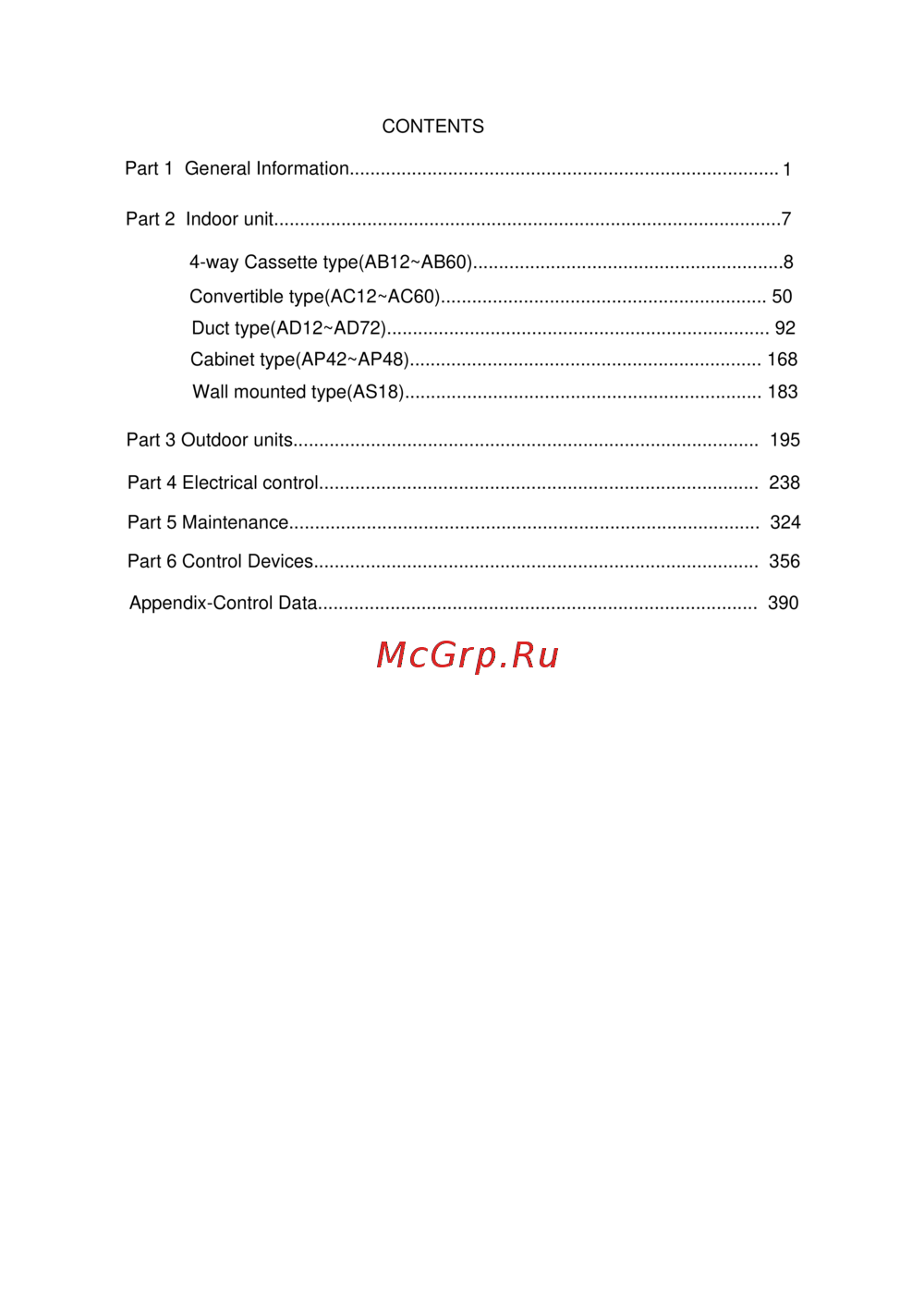
6. Installation
6.1 For AC12, AC18, AC24
Standard accessories:
The following installation parts are furnished.
Use them as required.
INSTALLATION PROCEDURE
PREPARING INDOOR UNIT INSTALLATION
1. REMOVE THE INTAKE GRILL
Install the room air conditioner as follows:
Open the intake grill and remove the
three or four or six screws.(Fig. 1)
When the directions are selected, drill a 7 cm dia. hole on the wall so
that the hole is tilted downward toward the outdoor for smooth water
flow. When the pipe is led out from the rear, make a hole in Fig.6, at
the position shown.
(Fig.3)
Drain hose (Left side) Drain hose (Right side)
Remark: The main unit can be wired before
the indoor unit is installed. Select
the most appropriate installation
order.
A. FLOOR CONSOLE TYPE
1. DRILLING FOR PIPING
Select piping and drain directions.(Fig.2) (Series14,18,24)
The piping and drain can be made in three directions as shown below.
down
Pipe connection requirement
Please refer to the specification to confirm the stop valve diameter and the permitted pipe drop and pipe length.
(Fig. 1)
Machine screw
Tapping screw
Tapping screw
Intake grill
(Fig. 2)
rear
right
1
2
3
4
5
1
2
4
1+1
2+2
No.
Accessory parts
Qty.
Remote controller
Battery
Wire clamp
Heat
insulation
sheathing
Screw
Screw cap
Remote
controller
bracket
6
7
1
1+1
Installation
-76-
Содержание
1415- Part 1 general information
- Unitary smart
- Unitary smart
- Unitary smart
- Au362aleaa
- Unitary smart
- Unitary smart
- Unitary smart
- Part 2 indoor units
- Way cassette indoor unit
- Ab12 ab60
- Features
- Quiet operation
- New particular design
- Fresh air outlet for the unit with pb 700ia and pb 950ja panel
- Comfortable temperature control system
- Built in high head drain pump
- Clean to use without polluting the ceiling it has standard long acting filter screen to make the cleaning time
- Antifouling and movable baffle
- Advanced structure facilitating cleaning and installation
- The suction grille can be rotated by 90 degree and its installation direction can be selected randomly
- The movable baffle has antifouling design and can effectively control the airflow and air direction it is
- Reduced
- Largely extended when there are many units the operation of cleaning and maintenance will be largely
- Features
- Efficient gray moire bactericidal filter give you a healthy breath
- Efficient filter option
- Specifications
- For dc inverter unit
- 840 240 9 3 0 9 3 0 3 3 0 pvc 26 32
- Specifications
- Remote or wired
- Inner grooved type 7 0 9
- Inner grooved type 7
- 950 80 980 980 100
- Specifications
- 950 60 985 985 115
- Pvc 26 32 remote or wired
- Inner grooved type 7 0
- Specifications
- Pvc 26 32
- 950 60 985 985 115
- 42 37 38 45
- Specifications
- Pvc 32 26
- Remote 0010451255
- Pvc 14 16
- Inner grooved pipe 7 0 72
- For fixed frequency unit
- 680 380mm pvc 26 32 remote
- 570 260mm
- 40 32 18 23 700 700 60mm 740 750 115mm
- Specifications
- Specifications
- Pvc 26 32 remote wired optional
- Inner grooved type 7 0 9
- Inner grooved pipe 7 0 9
- 950 80 980 980 100
- 950 60 pb 950ja 985 985 115
- 840 240 9 3 0 9 3 0 3 3 0
- 840 240
- Pvc 26 32
- Inner grooved type 7 0 9
- 985 115 6 9
- 950 80 980 980 100
- 840 240 9 3 0 9 3 0 3 3 0
- 32 950 950 60 pb 950ja
- 0 9 3 0 3 3 0
- Specifications
- Specifications
- Remote
- Inner grooved 7
- 950 60 985 985 115
- 840 290mm 93 0 9 30 390mm pvc 26 32
- Specifications
- Remote wired optional
- Pvc 32 26
- Inner grooved pipe 7
- Inner grooved 7
- 950 0 985 985 115
- 925 390mm pvc 26 32 remote
- 840 290mm
- Specifications
- Installation state the unit should be placed on the flat floor or be mounted in horizontal direction testing method
- Indoor temp
- Performance curves
- Heating performance curves ab122acera au122aeera
- Curves
- Cooling performance curves ab122acera au122aeera
- Performance curves
- Performance curves
- Performance curves
- Performance curves
- Indoor temp
- Cooling performance curves ab482aeera au48naiera
- Cooling capacity and power input w
- Cooling capacity 20 power input 25 cooling capacity 25 power input 32 cooling capacity 32 power input 35 cooling capacity 35 power input 40 cooling capacity 40 power input
- 12 20 14 22 16 25 18 27 19 30 22 32 23
- Performance curves
- Ab422aeeaa
- Performance curves
- Indoor db wb
- Third octave band frequency hz
- Sound pressure level db
- Noise level
- 3 octave band noise level ab182acera
- Noise level ab362aeera
- Noise level
- Heating middle
- Heating low
- Heating high
- Fan low
- Cooling middle
- Cooling low
- Cooling high
- 12 17 22 27 32 37 42 47 52
- Third octave band frequency hz
- Sound pressure level db
- Fan middle
- Fan low
- Fan high
- Cooling high
- Sound pressure level db
- Noise level
- For fix frequency unit
- 11 14 17 20 23 26 29 32 35 38 41 44 47 50 53
- Third octave band frequency hz
- Sound pressure level db
- Noise level
- 3 octave band noise level ab282aceaa
- 13 18 23 28 33 38 43 48 53 58
- 13 18 23 28 33 38 43 48 53
- Sound pressure level db
- Noise level
- Heating med
- Heating low
- Heating high
- Fan med
- Fan low
- Fan high
- Cooling med
- Cooling low
- Cooling high
- Fan low
- Fan high
- Cooling middle
- Cooling low
- Cooling high
- Third octave band frequency hz
- Sound pressure level db
- Noise level ab602aceaa
- Noise level
- Heating middle
- Heating low
- Heating high
- Fan middle
- B cooling temperature distribution
- Air velocity distribution
- A cooling air velocity distribution
- Cooling blowy angle 40
- C heating air velocity distribution
- B cooling temperature distribution
- Air velocity distribution
- A cooling air velocity distribution
- Temperature distribution
- Heating blowy angle 70 air velocity distribution
- D heating temperature distribution
- Temperature distribution
- Cooling blowy angle 40
- B cooling temperature distribution
- Air velocity distribution
- A cooling air velocity distribution
- Temperature distribution
- Cooling blowy angle 40
- B cooling temperature distribution
- Air velocity distribution
- A cooling air velocity distribution
- Dimension
- Ab12 ab18 used for the unit with pb 700ia panel
- Ab24 ab28 used for the unit with old pb 950ia panel and ab242aeera ab242aeeaa
- View d
- Dimension
- Ab282aeeaa used for the unit with new pb 950ja panel
- View d
- View c
- View a
- Dimension
- Ab28 ab36 ab42 ab48 used for the unit with new pb 950ja panel
- Dimension
- Ab48 ab60 used for the unit with pb 1340ia panel
- Part name
- For ab122aceaa ab182aceaa ab122acera ab182acera
- Part name
- Installation
- Installation
- Installation
- Installation
- Installation
- Installation
- Installation
- Installation
- Installation
- Convertible indoor unit ac12 ac60
- Convertible type
- Streamline appearance
- Optional installation mode
- Optional drain water modes
- Fresh air intake
- Features
- Automatically control of airflow direction
- Long life and high efficiency air purify filter
- Convertible type
- Variable control mode
- Ultra thin unit body only thick 199 mm
- Particular drive devic
- Specifications
- For dc inverter unit
- Specifications
- Remote or wired
- Pvc 18 20 remote or wired 48 46 44
- Pp20 25
- Inner grooved type 7 0 9
- Inner grooved type 7 0 40
- Energy efficiency stage
- 665 199 1150 750 300
- Specifications
- Pp 20 25
- Pp 20 25
- Specifications
- Specifications
- Remote wired
- Pvc 18 20
- For fixed frequency unit
- Specifications
- Inner grooved pipe 7 0 9
- 6 5 5 199 1150 750 300 pvc 18 20 remote wired optional
- Specifications
- Remote
- Inner grooved pipe 7 0 0
- Specifications
- Installation state the unit should be placed on the flat floor or be mounted in horizontal direction testing method
- Performance curves
- Curves
- 18 14 20 16 22 18 25 19 27 indoor wb db
- Performance curves
- Cooling performance curves ac182acera
- Ac182acera
- Performance curves
- Performance curves
- Indoor wb db
- Cooling capacity w power input w
- Ac362afera
- 6 heating capacity 7 6 power input
- 6 7 heating capacity 6 7 power input 4 5 heating capacity 4 5 power input 0 1 heating capacity 0 1 power input
- 5 heating capacity 6 5 power input
- 10 heating capacity 12 10 power input 16 15 heating capacity 16 15 power input
- 1 heating capacity 2 1 power input
- Performance curves
- Performance curves
- 3 octave band noise level ac182acera
- Third octave band frequency hz
- Sound pressure level db
- Noise level
- Third octave band frequency hz
- Sound pressure level db
- Noise level
- 3 octave band noise level a c 242a c era
- Noise level
- Fan high
- Third octave band frequency hz
- Sound pressure level db
- Noise level
- For fix frequency unit
- 3 octave band noise level ac182aceaa
- Noise level
- 3 octave band noise level ac282afeaa
- Third octave band frequency hz
- Sound pressure level db
- Sound pressure level db
- Noise level
- Air velocity distribution
- Air velocity distribution
- Air velocity distribution
- B cooling temperature distribution
- Air velocity distribution
- A cooling air velocity distribution
- B cooling temperature distribution
- Air velocity distribution
- A cooling air velocity distribution
- Dimension
- Ac28 ac36 ac48 ac60
- Ac12 ac18 ac24
- Part name
- Installation
- Installation
- Installation
- Installation
- Installation
- Installation
- Ac182acera ac242aceaa ac242acera
- Ac122aceaa ac122acera ac182aceaa
- 182 242
- Installation
- For ac28 ac36 ac48 ac60
- Installation
- Installation
- Installation
- Installation
- Installation
- Installation
- Installation
- Installation
- Installation
- Duct type
- Duct indoor unit ad12 ad72
- Ultra thin design and two side drainage pipe
- Special up drainage water pump optional
- Multi mode for installation
- High efficiency filter static pressure optional
- Free setting of air discharge duct
- Features
- Features
- Auto restart function optional
- Auto checking malfunction
- Variable control mode
- High sp design
- Specifications
- Pvc 16 12 wired control
- For dc inverter unit
- Specifications
- Inner grooved type 7 0 1
- 500 220 1174 54 5 2 80 pvc 16 12 remote or wired
- 45 41 37
- Inner grooved type 7 0 9
- Inner grooved type 7
- Energy efficiency stage
- 860 325 pvc 26 32 wired
- 650 300 1170 860 340 pvc 32 26
- 650 300
- 46 50 47 43 41
- Specifications
- Specifications
- Pvc 26 32
- Pvc 15 20
- Inner grooved type 7 0 79
- Energy efficiency stage c
- 46 42 62 70
- Tp2m 9 2 0 79
- Tp2m 7 0 71
- Specifications
- D 3 4 b
- 830 350 1430 940 420 pvc 26 32
- 49 47 43
- Specifications
- Pvc 26 32
- 830 350 1430 940 420
- Tp2m 9 2 0 0
- Wired control
- Specifications
- Pvc 16 12
- For fixed frequency unit
- Wired control
- Specifications
- Pvc 14 16 wired control
- Inner grooved pipe 7 0 1
- 500 220 1174 54 5 2 80 pvc 16 12
- 45 41 37
- Inner grooved type 7 0 9
- Inner grooved pipe 7
- 650 300 11 67 860 34 5 pvc 32 26
- 650 300 11 67 860 34 5
- 47 43 40 38
- Specifications
- Pvc 32 26 wired control
- Specifications
- Inner grooved type 9 2 0 5
- 830 3 5 0 940 105 0 42 0 pvc 32 26
- 49 47 43
- Specifications
- Inner grooved 7
- 742 270 1370 820 325
- Specifications
- Inner grooved 7
- 742 270 1370 820 325
- 49 47 43 wired
- Pvc 26 32
- 49 47 43
- 39 wired
- Tp2m 9 2 0 0
- Tp2m 7
- Specifications
- Wired control
- Tp2m 9 2 0 0
- Specifications
- Pvc 26 32 wired
- 830 350 1430 940 420 pvc 26 32
- 830 350 1430 940 420
- Tp2m 9 2
- Specifications
- Pvc 26 32 wired
- Performance curves
- Curves
- Performance curves
- Ad182amera
- Performance curves in cooling mode
- Performance curves
- Performance value
- Performance curves
- Operation condition
- Ad242alera cooling heating capacity esp curves
- Ad242alera
- Performance curves
- Indoor wb db
- Cooling capacity w
- Ad242alera heating performance curves
- Ad242alera cooling performance curves
- Indoor 27 19 outdoor 35 24 indoor 20 14 outdoor 7 6
- Ad362amera cooling heating capacity esp curves
- Ad362amera
- Ad362ahera
- Performance curves
- Pa power input
- Pa cooling capacity
- Performance curves
- Ad362ahera heating capacity curves
- Ad362ahera cooling capacity curves
- 18 14 20 16 22 18 25 19 27 22 30 24 32
- Super high high med low
- Static pressure pa
- Performance curves
- Ad482anera air flow and static pressure curves
- 10 20 30 40 50 60 70 80 90 100
- 8000 9000
- 5000 6000
- 13000 14000
- 12 20 14 22 16 25 18 27 19 30 22 32 23
- Performance curves
- Indoor wb db
- Cooling performance curves ad482ahera au48naiera
- Cooling capacity and power input w
- Cooling capacity 20 power input 25 cooling capacity 25 power input 32 cooling capacity 32 power input 35 cooling capacity 35 power input 40 cooling capacity 40 power input
- Performance curves
- Performance curves
- Operation condition
- Indoor 27 19 outdoor 35 24 indoor 20 14 outdoor 7 6
- Ad602ahera cooling heating curves esp
- Performance curves
- Performance curves
- Performance curves
- Ad482ameaa heating power input curves
- Ad482ameaa heating capacity curves
- Ad482aheaa cooling capacity curves
- Power input w
- Performance curves
- Indoor db wb
- Cooling capacity w
- Ad482aheaa cooling power input curves
- Power input w
- Performance curves
- Outdoor db
- Heating capacity w
- Ad482aheaa heating power input curves
- Ad482aheaa heating capacity curves
- 10 18 12 20 14 22 16 24 17 26 18
- Ad602aheaa cooling power input curves
- Ad602aheaa cooling capacity curves
- 30 35 24 25 16 15 8
- 16 27 19 27 20 27 21
- Power input w
- Performance curves
- Outdoor db wb
- Cooling capacity w
- Power input w
- Performance curves
- Outdoor db
- Heating capacity w
- Super high speed
- Super high high middle low
- Static pressure curves
- Low speed mid speed
- High speed
- External static pressure
- External static pressur
- Air flo
- Static pressure curves
- Ad282ameaa ad282amer
- Ad282aheaa high external static pressure unit
- Ad242amera ad242ameaa
- Static pressure curves
- Third octave band frequency hz
- Sound pressure level db
- Noise level
- 3 octave band noise level ad182amera
- Third octave band frequency hz
- Sound pressure level db
- Noise level
- 3 octave band noise level ad242alera
- 13 18 23 28 33 38 43 48 53
- Cooling low
- Cooling high
- Third octave band frequency hz
- Super heating high
- Super fan high
- Super cooling high
- Sound pressure level db
- Noise level ad362amera
- Noise level
- Heating middle
- Heating low
- Heating high
- Fan middle
- Fan low
- Fan high
- Cooling middle
- Cooling low
- Cooling high
- Third octave band frequency hz
- Super heating high
- Super cooling high
- Sound pressure level db
- Noise level ad362aneaa
- Noise level
- Heating middle
- Heating low
- Heating high
- Fan middle
- Fan low
- Cooling middle
- Third octave band frequency hz
- Noise level
- For fix frequency unit
- 3 octave band noise level ad182ameaa
- Third octave band frequency hz
- Super heating high
- Super fan high
- Super cooling high
- Sound pressure level db
- Noise level ad242ameaa
- Noise level
- Heating middle
- Heating low
- Heating high
- Fan middle
- Fan low
- Fan high
- Cooling middle
- Cooling low
- Cooling high
- Third octave band frequency hz
- Super heating high
- Super fan high
- Super cooling high
- Sound pressure level db
- Noise level ad282ameaa
- Noise level
- Heating middle
- Heating low
- Heating high
- Fan middle
- Fan low
- Fan high
- Cooling middle
- Cooling low
- Cooling high
- Third octave band frequency hz
- Super heating high
- Super fan high
- Super cooling high
- Sound pressure level db
- Noise level ad362ameaa
- Noise level
- Heating middle
- Heating low
- Heating high
- Fan middle
- Fan low
- Fan high
- Cooling middle
- Cooling low
- Cooling high
- Third octave band frequency hz
- Sound pressure level db
- Noise level
- 3 octave band noise level ad602aheaa
- Air velocity distribution
- For ad18
- Air velocity distribution
- Cooling
- Air velocity distribution
- Air velocity distribution
- Air discharge angle 5
- For ceiling concealed duct type esp 30pa
- Dimension
- Model ad182ameaa ad242ameaa ad282ameaa ad362ameaa ad242amera ad282amera ad362amera
- For medium static pressure duct type esp 50pa
- Dimension
- Model ad482ameaa
- Model ad362aneaa ad422aneaa ad482aneaa ad482anera
- Model ad282aheaa ad362aheaa
- For high static pressure duct type esp 100pa
- Dimension
- Model ad722aheaa
- Model ad482aheaa ad602aheaa
- Dimension
- Ad362ahera ad482ahera ad602ahera
- Part name
- Part name
- Installation
- For ceiling concealed duct type esp 30pa
- Installation
- Installation
- Installation
- Installation
- Installation
- Installation
- Installtion instruction for ad182 242 282 362 482ameaa and ad242 282 362amera
- Installation
- Installed
- Installation
- Imprope
- Installation
- Installation
- Installation
- Installtion instruction for ad362 422 482aneaa and ad482anera
- Installation
- Installation
- Installation
- Installation
- Installation
- Installation
- Installation
- For high static pressure duct type esp 100pa
- Installation
- Improper piping
- Installation
- Installation
- Installation
- Installation
- Installation
- Cabinet type
- Cabinet indoor unit
- Ap42 ap48
- D airflow
- Auxiliary electric heating function
- Optional healthy module
- Long distance air sending
- Features
- Features
- Bigger lcd screen
- Tp2m 7
- Specifications
- 600 350 1980 660 420 remote
- Specifications
- Power input curves in heating mode
- Performance curves
- Heating capacity curves
- Curves
- Power input curves in cooling mode
- Performance curves
- Cooling capacity curves
- Noise level
- Dimension
- Ap482akeaa
- Ap422aceaa
- Part name
- Ap482akeaa
- Ap422aceaa
- Installation
- Installation
- Installation
- Installation
- Installation
- Wall mounted type
- W all m ounted indoor unit
- Intelligent control
- Features
- Smart newly designed infrared remote controller
- Optional healthy module
- Newly designed v appearance indoor unit
- New designed fan and panel
- Specifications
- Installation state the unit should be placed on the flat floor or be mounted in horizontal direction testing method
- Performance curves in cooling mode
- Performance curves
- Curves
- Third octave band frequency hz
- Sound pressure level db
- Noise level
- 3 octave band noise level as182avera
- Part name
- Dimension part name
- Dimension
- Instructions to installation
- Installation
- Precaution
- Instructions to installation
- Installation
- Warning
- Installation
- Hose expander
- Accessories
- Installation
- Electrical wiring
- When connecting the cord before installing the indoor unit
- Installation
- Caution
- Installation
- Part 3 outdoor units
- Features
- New compresso
- Features
- Auto checking malfunction
- Advanced pwm control
- Specifications
- For dc inverter unit
- Specifications
- Item model
- Hlydrophilic al slit fin 9 2 3 1 43 60
- Defrosting auto 3 60
- Defrosting
- Weight net shipping 106 111
- Axial 2 860 40 0 8 8000
- W kg kg
- Au48naiera white
- Specifications
- Anb33fchmt mitsubishi
- Shf 4 10a
- 340 1250 10 95 4 10 1400
- Scroll
- R min 50
- Ou 3ph 380 400ac 50hz iu 1ph 220 230ac 50hz
- N v hz
- Mitsubishi 1700cm3
- Max piping length
- Max drop
- Item model au48naiera
- Specifications
- Com m unication wire 4 0 5m
- 9 2 flared
- 220 230 50
- X640x245 901x341x712
- X341x712
- Tp2m 9 2
- Total area m²
- Specifications
- Rotary
- R410a 1300 20
- Power cable power source n v hz start current a
- For fixed frequency unit
- Axial 1 840r min 50 0 6 2500
- Au122aeeaa white
- Hlydrophilic foil slit fin 7 3 1 6 43 60
- Axial 1 1000 50 0 6 3000
- Auto 3 57
- Au242ageaa
- 335 732 995 420 815 1 300 capillary
- Specifications
- Shf 4 10a 37
- Rotary
- Ph 220 230vac 50hz
- Pa290x3cs 4mu1 toshiba
- Hard startup
- Daphne fvc68d
- Axial 1 920 50 0 6 4000
- Axial 1
- Automatic 59
- Automatic 3 58
- Au28naheaa white
- 447 830 1130 490 930 capillary tube
- Specifications
- 340 840 10 95 4 1 0 9 90 capillary
- Shf 4 10a 40
- 1ph 220 230ac 50hz au362aleaa white
- Rotary
- 1 5500
- Ph 380 400vac 50hz
- Nn33ycamt mitsubishi
- L scroll inner thermal protection
- Inner grooved 9 2 2 1 43 60
- Hlydrophilic foil slit fin 7 4 2 1 43 60
- Specifications
- Specifications
- Fvc68d
- Capillary 2 150
- Axial 2
- Auto 3 60
- 40 0 8 7000
- 340 1250 10 95 4 10 1 400
- Specifications
- Shf 4 10a 55
- Scroll
- Jt170g p8y1 daikin
- Hlydrophilic foil slit fin 9 2 3 1 43 60
- Specifications
- Installation state the unit should be placed on the flat floor or be mounted in horizontal direction testing method
- Performance curves
- Curves
- Au182aeeaa
- Performance curves
- Au242ageaa
- Performance curves
- Au282aheaa
- Au362aieaa
- 12 20 14 22 16 25 18 27 19 30 22 32 24
- Performance curves
- Indoor db wb
- Cooling capacity curves
- Performance curves
- Heating capacity curves
- Cooling capacity curves
- Heating med
- Heating low
- Heating high
- Fan med
- Fan low
- Fan high
- Cooling med
- Cooling low
- Cooling high
- 3 octave band noise level au182afera
- Third octave band frequency hz
- Sound pressure level db
- Noise level
- Third octave band frequency hz
- Sound pressure level db
- Noise level
- Heating med
- Heating low
- Heating high
- Fan med
- Fan low
- Fan high
- Cooling med
- Cooling low
- Cooling high
- 3 octave band noise level au242agera
- Third octave band frequency hz
- Sound pressure level db
- Noise level au48naiera
- Noise level
- Heating middle
- Heating low
- Heating high
- Fan middle
- Fan low
- Fan high
- Cooling middle
- Cooling low
- Cooling high
- Cooling high
- Third octave band frequency hz
- 9 14 19 24 29 34 39 44 49 54 59 64 69
- Sound pressure level db
- 3 octave band noise level au182aeeaa
- Noise level
- Heating super high
- Heating med
- Heating low
- Heating high
- For fix frequency unit
- Fan super high
- Fan med
- Fan low
- Fan high
- Cooling super high
- Cooling med
- Cooling low
- 10 15 20 25 30 35 40 45 50 55 60 65 70
- Third octave band frequency hz
- Sound pressure level db
- Noise level
- Heating med
- Heating low
- Heating high
- Fan med
- Fan low
- Fan high
- Cooling med
- Cooling low
- Cooling high
- 3 octave band noise level au282aheaa
- Third octave band frequency hz
- Sound pressure level db
- Noise level
- Third octave band frequency hz
- Sound pressure level db
- Noise level
- Sound pressure level db
- Noise level
- Heating med
- Heating low
- Heating high
- Fan med
- Fan low
- Fan high
- Cooling med
- Cooling low
- Cooling high
- 9 14 19 24 29 34 39 44 49 54 59 64 69
- 20 25 30 35 40 45 50 55 60 65 70
- Third octave band frequency hz
- Dimension
- Au122aeeaa au1 8 2a eeaa au122aeera
- Au1 8 2a fera
- Dimension
- Au362aieaa au36naieaa au 48 nai ea a au60naieaa au362aiera au48naiera au60naiera
- Dimension
- Au362aleaa au42naleaa
- Dimension
- Au72nateaa
- Part name
- Refrigerant diagram
- High pressure switch 2 low pressure switch
- For fixed frequency units
- For au242ageaa au282 28naheaa au362 36naieaa au42naleaa au48n 60naieaa
- For au182aeeaa
- Refrigerant diagram
- High pressure switch 2 low pressure switch 3 for au182afera is 2 way stop valve 4 for au182afera is main capillary 5 for au182afera is sub capillary and single check valve for au182afera no 1 and 2 are avaliable
- For inverter units
- For au362a h era
- Refrigerant diagram
- Installation
- Installation
- Installation
- Installation
- Installation
- M should be confirm ed according to the value in specification
- Installation
- Installation
- Oil trap setting requirement
- Oil trap is required no mater the outdoor unit is upper or lower than indoor unit only when
- Installation
- Trap dimensions setting method install one oil trap for every 10 meters at the gas pipe
- The piping drop is more than 10m
- Sensor characteristic 76
- Part 4 electrical control
- Electrical wiring diagram and pcb photo 39
- To outdoor unit
- Electrical wiring diagram and pcb photo
- Circuit diagram of indoor unit
- Ab182acera
- Ab122acera
- Electrical wiring diagram and pcb photo
- E for ab122acera and ab182acera
- Electrical wiring diagram and pcb photo
- Circuit diagram of indoor unit
- Bm3 and bm4 3 user should not to set bm1 and bm2
- Ab362aceaa ab422aeeaa ab482aeeaa
- Ab122aceaa ab182aceaa
- W white b black br brown bl blue r red y yellow y g yellow green temp temperature
- To outdoor unit power supply
- To outdoor unit
- Remote centralized controller
- Refer to operation manual to se
- Note 1 the parts in dashed frame are optional 2
- Led3 cn3
- Led2 led1
- Itophome
- Cn21 cn22
- Cn15 cn20
- Electrical wiring diagram and pcb photo
- Electrical wiring diagram and pcb photo
- Ac122 182 242acera ac122 182 242aceaa ad122alera ad182amera ad122 182aleaa
- Ab242 362acera ab242 282 482 602aceaa ac 282 362 482 602afeaa ad242alera ad242aleaa
- W white b black r red y yellow or orange bl blue br brown
- Remote
- Receiver
- Receive board
- Electrical wiring diagram and pcb photo
- Circuit diagram of indoor unit 0010576546
- Ad242 282 362 482ameaa ad242 282 362amera
- Receiver
- Receive board
- Please refers to the appendix
- Note for the above indoor units the pcb code is 0010451690e 0010451167e the detail information
- Fan speed control board 001a3300352e
- Electrical wiring diagram and pcb photo
- Controller centralized
- Controller
- Ad 282 362 482 602aheaa
- W white b black r red y yellow or orange bl blue br brown
- Up down
- To outdoor unit
- Switch
- Room pipe
- Remote
- Fan speed adjusting board test method
- Electrical wiring diagram and pcb photo
- Electrical wiring diagram and pcb photo
- Electrical wiring diagram and pcb photo
- E information function selection
- Electrical wiring diagram and pcb photo
- Electrical wiring diagram and pcb photo
- Electrical wiring diagram and pcb photo
- Electrical wiring diagram and pcb photo
- Electrical wiring diagram and pcb photo
- Wired remote control
- Wire control indoor slave master unit
- Temp compensation available inavailable
- Sw1 sw2
- J62 sw3 4 j63 sw3 3 j64 sw3 2 j65 sw3 1
- J60 sw4 2 j61 sw4 1
- I nterligent wind single blade
- Hp convertible other
- Electrical wiring diagram and pcb photo
- Address 1 2 3 4 1 2 3 4
- Ac282 362afe ra
- Electrical wiring diagram and pcb photo
- Electrical wiring diagram and pcb photo
- W white
- Electrical wiring diagram and pcb photo
- Ap482akeaa
- Y g yellow green
- Wiring diagram of wall mounted unit
- Electrical wiring diagram and pcb photo
- As182avera
- Wired controller
- W white b black r red y yellow or orange bl blue br brown
- To outdoor unit
- Remote
- Receiver
- Receive board
- Electrical wiring diagram and pcb photo
- Controller centralized
- Ad482ahera ad482anera
- Ac 2afe ra
- Electrical wiring diagram and pcb photo
- And 0151800077 dip switch function defination sw1 sw2 used for centralized network control
- Ab482aeera
- Electrical wiring diagram and pcb photo
- Address selection and roomcard switch or and function selection
- Electrical wiring diagram and pcb photo
- Electrical wiring diagram and pcb photo
- Au122aeera
- Sw05 on 0010452047e is used for factory quality control engineers the default position is off off off off for au122aeera and there are also module board 0010404120 and capacity board 0010403697
- Outdoor indicator board 0010452047e
- O u tdoor pcb 0151800037 for au122aeera
- Electrical wiring diagram and pcb photo
- Wiring diagram of outdoor unit
- To indoor unit
- Power supply
- Electrical wiring diagram and pcb photo
- Cn9 cn8 cn26 cn27 cn7 cn6
- Cn16 cn15 cn17 cn21
- To power supply
- To indoor unit
- Reactor
- Outdoor indicator board 0010452047e
- Outdoor filter board 0010403645
- Electrical wiring diagram and pcb photo
- Control
- Cn8 cn2
- Circuit diagram of outdoor unit
- Circuit board
- Circuit
- Capacitor
- Outdoor pcb 0010452929
- Electrical wiring diagram and pcb photo
- Number 4 moter selectio
- Apy module
- Number 4
- Ac 3 speed
- Number 3
- Number 2
- Number 1
- Normal defrost
- Normal
- Module selectio
- Homemade moudule
- Without
- Electrical wiring diagram and pcb photo
- Triplicate phase
- Defrost selectio
- Single phase
- Dc fan motor
- Outdoor horse powe
- Compelling selection
- Number 8 quiet operation selectio
- Compelling heating
- Number 7 power source selection
- Compelling defrost
- Number 6 defrost paramete
- Compelling cooling
- Outdoor pcb 0151800054
- Electrical wiring diagram and pcb photo
- Wiring diagram b25 4t
- Power m odule
- Electrical wiring diagram and pcb photo
- For fixed frequency outdoor units
- Electrical wiring diagram and pcb photo
- Circuit diagram of outdoor unit
- Circuit diagram of outdoor unit
- Y g yellow green
- R red w white bl blue gr gray b black
- Electrical wiring diagram and pcb photo
- Dashed parts 3 is optional in low ambient temp cooling type and there is no fan motor speed contrller in normal type
- Dashed parts 1 2 is not available in only cooling type
- Electrical wiring diagram and pcb photo
- Circuit diagram of outdoor unit
- Electrical wiring diagram and pcb photo
- Electrical wiring diagram and pcb photo
- Sensor characteristic
- Model name code sub part code characteristic
- Sensor characteristic
- Sensor characteristic
- Sensor characteristic
- Sensor characteristic
- Electric control functions
- Electric control functions
- Electric control functions
- Electric control functions
- Electric control functions
- Electric control functions
- Electric control functions
- Electric control functions
- Rising
- Falling
- Electric control functions
- Electric control functions
- Electric control functions
- Electric control functions
- Electric control functions
- Electric control functions
- Electric control functions
- Electric control functions
- Electric control functions
- Electric control functions
- Electric control functions
- Electric control functions
- Cool mode control
- Electric control functions
- Electric control functions
- System protection
- Sleep time 1 2 8
- Sleep time 1 2 5 8
- Sleep function
- Electric control functions
- Electric control functions
- Electric control function for the unit with 0010452042e pcb as182avera 3
- Electric control functions
- Ts 2 ts 3 ts 4
- Ts 1 ts 2
- Electric control functions
- Electric control functions
- Electric control functions
- Electric control functions
- Electric control functions
- Electric control functions
- System protection function
- Electric control functions
- Compressor crankcase heater working condition
- Electric control functions
- Outdoor pcb test
- Electric control functions
- Electric control functions
- Electric control function for dc inverter outdoor unit era
- Many differences please refer to the corresponding service manual to reach the detailed information note take the electric control function of au362ahera as an example as for other models there are
- Electric control functions
- The movement of valve after compressor startup shut off
- Heat 52 e 400 e standard open
- Electric control functions
- E 80 e
- Angle tolerance
- Way valve on off 15 seconds e 2 minutes and 55 seconds
- Electric control functions
- Compressor on off
- On unloading valve sv1 off auto
- Off off
- Hz e 60s
- Hz 0hz 10s
- Expansion valve pmv
- Electric control functions
- On unloading valve sv1 sv2 off off
- On high speed
- Max 10 minutes off
- Expansion valve pmv
- Electric control functions
- Beginning end
- 1hz second
- Purpose make compressor frequency control if the discharging temp is too high to lower the discharging
- P reduce at the speed of 1hz 10s
- Over current protection
- It is below 48 the unit will resume to be normal
- Indoor heat exchanger temperature will check the indoor coil temperature if it is over 55 the unit will
- In heating indoor tc high temperature protection
- Electric control functions
- Discharging temp td
- The compressor will stop and alarm if current exceed the 19 a e for 5 seconds contineously during
- Compressor startup
- Temp efficiently and ensure the system can run normally
- Td high temperature protection
- Sensor detect method 100 times the cycle of procedure is about 5ms detect method for every time
- Sample 8 times contineously sort order and then adopt the average of the 2 middle values adopt the average
- Reduce the compressor motor speed to perform the indoor heat exchanger temperature overhigh protection if
- R rise at the speed of 1hz 10s
- Q remain the previous value
- When tm 95 last 5s force thermostat off restorable if
- Restart after 3 minutes reduce fqy rapidly 1hz s
- Remain fqy
- Reduce fqy slowly 1hz 10s
- Module temp tm
- Increase fqy slowly 1hz 10s
- Electric control functions
- 11 increase fqy slowly 1hz 10s 9 remain fqy 6 reduce fqy slowly 1hz 10s
- Over high and high pressure switch acts for over 30 seconds the compressor and outdoor motor will stop 3
- Outdoor defrosting temp sensor when ambient temp is below 5 detect after having start for 3 minutes
- Minutes later the unit will resume if in 60 minutes the unit stops for 3 times because of overhigh pressure the
- Minutes later after compressor starts up the system will check the pipe pressure if the pipe pressure is
- Low pressure switch
- Indoor pipe temp is abnormal outdoor default cooling temp 5 heating temp 40 the above
- In defrosting and in 3 minutes after defrosting is over if sensor is abnormal there will not alarm
- In 6 minutes after defrosting is over low pressure switch will be shielded
- High pressure switch
- When compressor works if low pressure switch acts for 60 seconds contineously the unti will alarm
- Failure code and troubleshooting
- When compressor stops if low pressure switch acts for 30 seconds contineously the unti will alarm
- Failure
- When compressor starts up in 3 minutes low pressure switch will be shielded
- Ensure that alarm indicating time is over 2 minutes and 50 seconds
- The unit enter compulsory heating operation as follow
- Electric control functions
- Compulsory heating operation
- Temperatures are normal
- Compulsory cooling operation the unit enter compulsory cooling operation as follow
- System will alarm then compressor will not start up again when being electrified after being powered off the
- Alarm lamp is off when no failure flash when failure occurs the different flash time means different
- Protection will be cancelled
- Troubleshooting 09
- Part 5 maintenance
- Maintenance
- Failure code 01
- Failure code
- The others are the same as inverter unit
- Failure code
- For ap422aceaa
- Failure code
- Fault description
- Failure code
- For outdoor units
- For fixed frequency outdoor unit eaa
- Failure description
- Failure code
- Code on wired controller flash times of indoor receiver board
- Trouble description
- For au12 1 for inverter outdoor unit era
- Failure code
- Display of led borad led 5 4 3 2 1 analyze and diagnose flash times of led on mainborad
- Failure code
- For au28 36
- Failure code
- 2 not resumable alarm but if in 60 minutes unrestorable failure occurs 3 times it can be resumed
- 1 resumable alarm and will be sent to indoor unit marked with
- Only when being electrified after being powered off marked with
- Troubleshooting
- For fixed frequency units eaa
- Troubleshooting
- Low pressure protection wired controller shows
- Troubleshooting
- High pressure protection wired controller shows
- Troubleshooting
- Troubleshooting
- Troubleshooting
- Troubleshooting
- Troubleshooting
- Troubleshooting
- No it s split winding type motor
- Fault in indoor fan motor
- Troubleshooting
- Troubleshooting
- Sensor failure
- For dc inverter units era 2 for au122aeera
- Alarm condition ambient temperature sensor is in short circuit or open circuit
- Troubleshooting
- Troubleshooting
- Troubleshooting
- Troubleshooting
- For au182afera and au242agera
- Alarm condition outdoor indicator displays 10111 00001 or 01111 10000 100001 or 10100
- Troubleshooting
- Outdoor indicator displays 00010 alarm condition outdoor dc motor is blocked rotor or broken abnormal this fault is only used when indoor unit is with dc fan motor
- For wall mounted unit
- Communication error between indoor and outdoor units outdoor indicator shows 00011
- Troubleshooting
- Compressor discharging temperature protection outdoor indicator shows 00100 alarm condition within half an hour after compressor is running compressor discharging temp is over 120degree for 3 times continously
- When compressor starting up unit stops abnormally and can not start up normally
- Troubleshooting
- Running state detecting abnormal
- Replace compressor
- Re electrified after power off check if compressor can start up normally
- Outdoor indicator shows 10011 alarm condition when compressor is running the unit will be abnormal or stop
- Outdoor indicator shows 10011
- Outdoor indicator shows 01110 alarm condition eeprom is fault or data is missing
- Outdoor indicator shows 01110
- Eliminate other troubles
- Eeprom is abnormal
- Eeprom data is missing replace pcb
- Check if eeprom welded points on outdoor pcb is in good condition
- Adjust eeprom welded point
- Outdoor indicator shows 11000
- Low pressure abnormal
- Troubleshooting
- Outdoor low pressure abnormal
- Outdoor indicator shows 11000 alarm condition outdoor system pressure is lower than 0 5mpa
- Troubleshooting
- O utdoor power module failure
- Led1 is the indicator for communication between indoor and outdoor unit led2 is the failure indicator
- For au362ahera
- Troubleshooting
- Replace outdoor pcb
- Replace indoor pcb
- No adjust the position
- Eliminate other faults
- Compressor discharging temperature protection outdoor indicator led2 flashes 4 times alarm condition within one hour after compressor is running compressor discharging temperature is over 120degree for 3 times continously
- Adjust wiring and power supply note not connect l n wrong
- Adjust piping
- Adjust piping
- Yes replace sensor
- Troubleshooting
- Outdoor power supply is abnormal alarm condition if power supply is not 50hz as standard which will affect the normal communication and cause air conditioner bad operation
- Outdoor high pressure protection outdoor indicator flashes 8 times alarm condition when compressor running high pressure is over 4 mpa for 30 seconds continously
- Eeprom is abnormal
- Check if the piping is blocked
- Alarm condition eeprom is fault or data is missing
- Adjust wiring
- Adjust refrigerant
- Troubleshooting
- Measure actual pressure by a pressure gauge to adjust the output failure
- Part 6 control devices
- Infrared controller
- Infrared controller
- Infrared controller
- Infrared controller
- Infrared controller
- Infrared controller
- Infrared controller
- Infrared controller
- Infrared controller
- Infrared controller
- Infrared controller
- Infrared controller
- Infrared controller
- Wired controller
- Wired controller
- Wired controller
- Wired controller
- Wired controller
- H outdoor total capacity actual value decimal
- G preset
- Wired controller
- In check mode press check to quit the check mode and go into normal running in check mode press check to quit the check mode and go into normal running mode
- Wired controller
- Wired controller
- 9 off off off on off off off
- 8 off off off off on on on
- 7 off off off off on on off
- 14 off off off on on off on
- 13 off off off on on off off
- 12 off off off on off on on
- 11 off off off on off on off
- 10 off off off on off off on
- 86 on off on off on off on
- 85 on off on off on off off
- 84 on off on off off on on
- 83 on off on off off on off
- Wired controller
- 94 on off on on on off on
- 93 on off on on on off off
- 92 on off on on off on on
- 91 on off on on off on off
- 90 on off on on off off on
- 89 on off on on off off off
- 88 on off on off on on on
- 87 on off on off on on off
- Wired controller
- Function difference between simple wired controller and the standard one
- Function difference between master wired controller and slave one
- Electrical functions of wired controller
- C two wired controllers control one indoor unit the wired controller
- B one wired controller controls one indoor unit and the indoor unit connects
- A one wired controller can control max up to 16 sets of indoor units and 3
- With the wired controller through 3 pieces of polar wire
- Wiring connections of wired controller
- Wired controller
- There are three methods to connection wired controller and the indoor units
- The master unit through 2 pieces of polar wire
- Pieces of polar wire must connect the wired controller and the master unit the
- Indoor unit connected with wired controller directly the others connect with
- The communication wiring is 4 meter long if the actual length is more than it
- Terminal a b c of wired controller respectively
- Please distribute wiring according to below table
- One side of the shielded sheet of communication wire must be earthed
- Master wired controller and indoor unit master and slave wired controllers are
- Connected with indoor unit is called master one the other is called slave one
- Communication wiring
- All connected through 3 pieces of polar wire
- Accessories 3 core terminal 1 white 2 yellow 3 red is connected with the
- Wired controller
- The wired controller is equipped with special communication wiring in the
- Weekly timer
- Weekly timer
- Weekly timer
- Central controller ycz a001
- Central controller
- Central controller
- Cn2 cn2 cn2 cn2
- Central controller
- Central controller
- Central controller
- Unitary free r410a on off
- No series type model pcb code controller code
- Appendix control data
- Appendix
- Unitary smart r410a dc inverter
- No series type model pcb code controller code
- Appendix
Похожие устройства
-
 Haier AB602ACERAТехнические данные
 -
 Haier AB602ACERAСервис мануал
 -
 Haier AB602ACERAИнструкция по монтажу
 -
 Haier AB602ACERAИнструкция по эксплуатации
 -
Haier AB602ACEAAСервис мануал
-
Haier AB602ACEAAИнструкция по монтажу
-
Haier AB602ACEAAИнструкция по эксплуатации
-
Haier AB482AEEAAТехнические данные
-
Haier AB482AEEAAСервис мануал
-
Haier AB482AEEAAИнструкция по эксплуатации
-
Haier AB482AEEAAИнструкция по монтажу
-
Haier AB482ACEAAТехнические данные
Подробное руководство по установке кондиционеров. Узнайте, как правильно установить внутренний блок, подготовить место и выполнить необходимые подключения.