
Haier 4U36MS2VHB Инструкция по монтажу онлайн
Содержание
- Ductless split heat pump 1
- Indoor unit installation cassette 14 19 1
- Indoor unit installation wall mount 20 24 1
- Installation manual 1
- Outdoor unit installation 1
- Remote controller 5 28 1
- Introduction overview 2
- Outdoor unit installation 2
- Outdoor unit product information 2
- Page 2 installation 2
- As temperature setpoint is reached the inverter will run everything slowly to provide small amounts of capacity to keep the rooms comfortable at times the air coming out of the indoor units will be close to or at room temperature this is normal 3
- As the temperature in the zones gets closer to the setpoint requirement the inverter will slow everything down this is normal operation 3
- Cool mode 14 f 114 f heat mode 5 f 74 f 3
- English 3
- Installation page3 3
- Introduction overview 3
- Matching up the outdoor unit to indoor units 3
- Operating temperature ranges 3
- Outdoor unit product information 3
- Temperature control and the inverter 3
- The approved combinations of indoor unit capacity and outdoor unit model are shown at the right the capacity ratings can be matched to any of the high wall cassette or ducted concealed models 3
- The outdoor unit inverter will operate the compressor outdoor fan motor and indoor fan motor at the proper speed to provide enough capacity to satisfy the heat load from all operating indoor units 3
- The systems are not rated for use of only 1 indoor unit do not vary from the available combinations in these tables 3
- This precise match of capacity and load is how ductless air conditioners acheive high efficiency ratings 3
- When ports are not used always connect the refrigerant lines to circuits located at the outdoor units lowest possible connection use line reducing fittings to transition from the outdoor port size to the required port size of the indoor unit 3
- English 4
- Introduction overview 4
- Page 4 installation 4
- Product specifications 4
- English 5
- Installation pages 5
- Outdoor unit clearances 5
- Required tools for installation procedure for selecting the location 5
- Step 1 preparation 5
- Attaching drain elbow to outdoor unit 6
- English 6
- Page 6 installation 6
- Piping limits pipe size 6
- Set the outdoor unit 6
- Step 2 installation of the outdoor unit 6
- Step 3 refrigerant line connections 6
- Connection priority 7
- English 7
- Installation page 7 7
- Step 3 refrigerant line connections 7
- English 8
- Installation 8
- Leak test 8
- Page 8 8
- Piping connection 8
- Step 3 refrigerant line connections 8
- Step 4 leak test and evacuation 8
- Installation page 9 9
- Step 4 leak test and evacuation 9
- System evacuation 9
- English 10
- Page 10 installation 10
- Step 5 electrical connections 10
- Wiring unit 10
- Cn2 cn3 11
- English 11
- I i i i i i i i i n l i 1 i i 11
- Installation page 11 11
- Step 5 electrical connections 11
- Wiring error check 11
- Check items for test run 12
- English 12
- Page 12 installation 12
- Step 6 charging 12
- Step 7 system test 12
- Step 8 explaining operation to the end user 12
- English 13
- Installation page 13 13
- Outdoor unit installation complete 13
- Seacoast application 13
- Built in condensate the motorized louver is controlled via the remote control the louver has indicator lights that communicate function and diagnostic information to the user and service technician 14
- Cassette indoor unit specifications 14
- Cassette product information 14
- English 14
- Factory supplied remote 14
- Included with the cassette unit is factory provide insulating tape this tape should be placed over the refrigerant piping connections at the indoor unit to prevent sweating 14
- Indoor unit installation cassette 14
- Introduction overview 14
- Optional fresh air can be piped into the cassette assembly the knockout is located on the side of the cassette assembly if fresh air is desired be certain to filter the air prior to it entering the cassette a 4 galvanized pipe should be used to pipe in the fresh air 14
- Page 14 installation 14
- Pump and float switch 14
- The cassette indoor air handler ships consists of a cassette assembly and operational louver the cassette indoor unit is operated via a factory supplied remote control wired controller is optional 14
- The cassette unit has a built in condensate pump and associated float switch that manages the operation of the condensate pump a flexible hose is included with the cassette unit this hose connects the cassette condensate drain outlet to the buildings condensate drain system 14
- The cassette unit receives 230 volt line voltage from a connection at the outdoor condensing unit there is no requirement for independent line voltage connections 14
- The cassette unit will install between standard dropped ceiling grids it is mounted using threaded rods that fit into brackets that are located at all four corners of the cassette assembly 14
- English 15
- Fresh air knock out 15
- In under 15
- Installation page 15 15
- Introduction overview 15
- Page 16 installation 16
- Required tools for installation procedure for selecting the location 16
- Step 1 preparation 16
- Threaded rod mounting information 16
- Installation page 17 17
- Step 2 installation of the cassette unit 17
- Step by step guide to cassette installation 17
- English 18
- Page 18 installation 18
- Step 2 installation of the cassette unit 18
- English 19
- Indoor cassette unit installation complete 19
- Installation page 19 19
- Step 3 electrical connections 19
- Step 4 louver installation 19
- Step 5 pull vacuum on system 19
- A display indicator located on the front panel of the unit provides temperature and operating modes of the system it can also display error code conditions of the system 20
- A motorized louver at the front of the unit is controlled via the remote control the louver may be set to either oscillate or remain in a stationary position mounting bracket 20
- Carbon and catechin filters clip in to the filter screens to help filter the air 20
- Indoor unit installation wall mount 20
- Introduction overview 20
- Manual vanes located behind the louver may be set to help the direction of airflow 20
- Page 20 installation 20
- Piping to the unit may be routed from one of several directions left left back left down right right back and right down 20
- The wall mount indoor air handler consists of a single compact unit operated via a factory supplied remote control 20
- The wall mount unit receives 230 volt line voltage from a terminal connection at the outdoor condensing unit there is no requirement for independent line voltage connections 20
- Wall mount indoor unit specifications 20
- Wall mount product information 20
- Clearances of indoor and outdoor units 21
- English 21
- Installation page 21 21
- Required tools for installation procedure for selecting the location 21
- Step 1 preparation 21
- Attaching the mounting plate to the wall 22
- English 22
- Page 22 installation 22
- Step 2 installation of the wall mount unit 22
- English 23
- Installation page 23 23
- Mounting plate 23
- Mounting the indoor unit onto the wall plate 23
- Step 2 installation of the wall mount unit 23
- English 24
- Indoor wall mount unit installation complete 24
- Page 24 installation 24
- Step 3 electrical connections 24
- Step 4 pull vacuum on system 24
- Auto button 25
- Cool button 25
- Dry button 25
- English 25
- Fan button 25
- Functions 25
- Power button 25
- Q heat button 25
- Q turbo quiet button 25
- Remote control functions page 25 25
- Remote controller 25
- Temperature buttons 25
- English 26
- Louver swing button horizontal 26
- Louver swing button vertical 26
- Page 26 remote control functions 26
- Timer off button 26
- Timer on button 26
- W w w w 26
- English 27
- Extra function button 27
- Remote control functions page 27 27
- Sleep button 27
- Confirm cancel button 28
- English 28
- Health button________________________________ 28
- Light button 28
- Lock button 28
- Page 28 remote control functions 28
- Reset button 28
- Www haier com 30
Похожие устройства
- Haier AD07SL2VHA Руководство по монтажу
- Haier AD07SL2VHA Инструкция по монтажу
- Haier AD09SL2VHA Руководство по монтажу
- Haier AD09SL2VHA Инструкция по монтажу
- Haier AD12SL2VHA Руководство по монтажу
- Haier AD12SL2VHA Инструкция по монтажу
- Haier AD18SL2VHA Руководство по монтажу
- Haier AD18SL2VHA Инструкция по монтажу
- Haier AD07SL2VHB Руководство по монтажу
- Haier AD09SL2VHB Руководство по монтажу
- Haier AD12SL2VHB Руководство по монтажу
- Haier AD18SL2VHB Руководство по монтажу
- Haier AM24LP2VHA Спецификация
- Haier AM24LP2VHA Технические данные
- Haier AM24LP2VHA Руководство по монтажу
- Haier AM24LP2VHA Инструкция по монтажу
- Haier AM36LP2VHA Спецификация
- Haier AM36LP2VHA Технические данные
- Haier AM36LP2VHA Руководство по монтажу
- Haier AM36LP2VHA Инструкция по монтажу
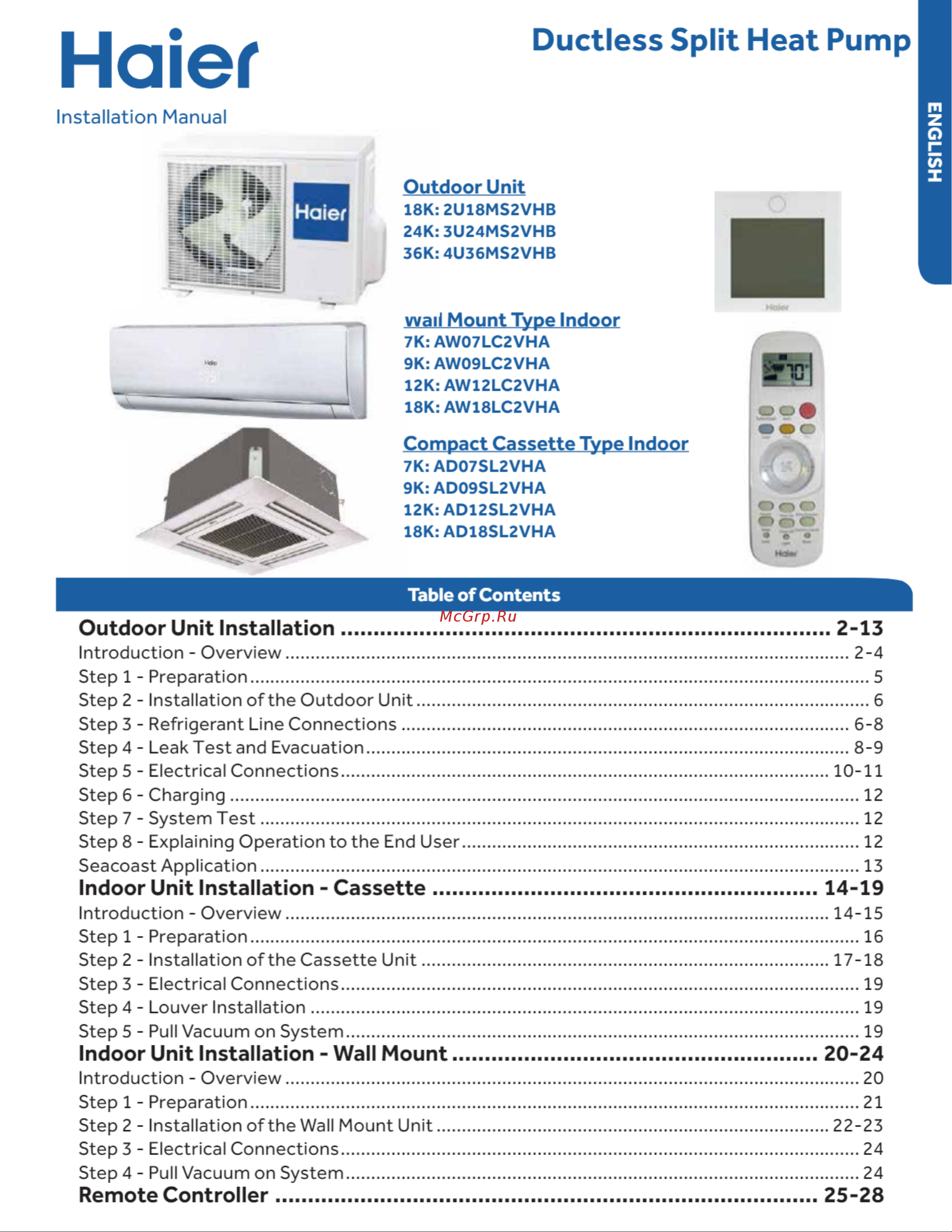
Ductless Split Heat Pump ENGLISH Haier Installation Manual Outdoor Unit 18K 2U18MS2VHB 24K 3U24MS2VHB 36K 4U36MS2VHB wail Mount Type Indoor 7K AW07LC2VHA 9K AW09LC2VHA 12K AW12LC2VHA 18K AW18LC2VHA Compact Cassette Type Indoor 7K AD07SL2VHA 9K AD09SL2VHA 12K AD12SL2VHA 18K AD18SL2VHA Table of Contents Outdoor Unit Installation 2 13 Introduction Overview 2 4 Step 1 Preparation 5 Step 2 Installation of the Outdoor Unit 6 Step 3 Refrigerant Line Connections 6 8 Step 4 Leak Test and Evacuation 8 9 Step 5 Electrical Connections 10 11 Step 6 Charging 12 Step 7 System Test 12 Step 8 Explaining Operation to the End User 12 Seacoast Application 13 Indoor Unit Installation Cassette 14 19 Introduction Overview 14 15 Step 1 Preparation 16 Step 2 Installation ofthe Cassette Unit 17 18 Step 3 Electrical Connections 19 Step 4 Louver Installation 19 Step 5 Pull Vacuum on System 19 Indoor Unit Installation Wall Mount 20 24 Introduction Overview 20 Step 1 Preparation 21 Step 2 Installation ofthe Wall Mount Unit 22 23 Step 3 Electrical Connections 24 Step 4 Pull Vacuum on System 24 Remote Controller 25 28