
Haier HB6000VD1M22 Сервис мануал онлайн
SERVICE MANUAL
ƽ
Features
zHigh efficiency design
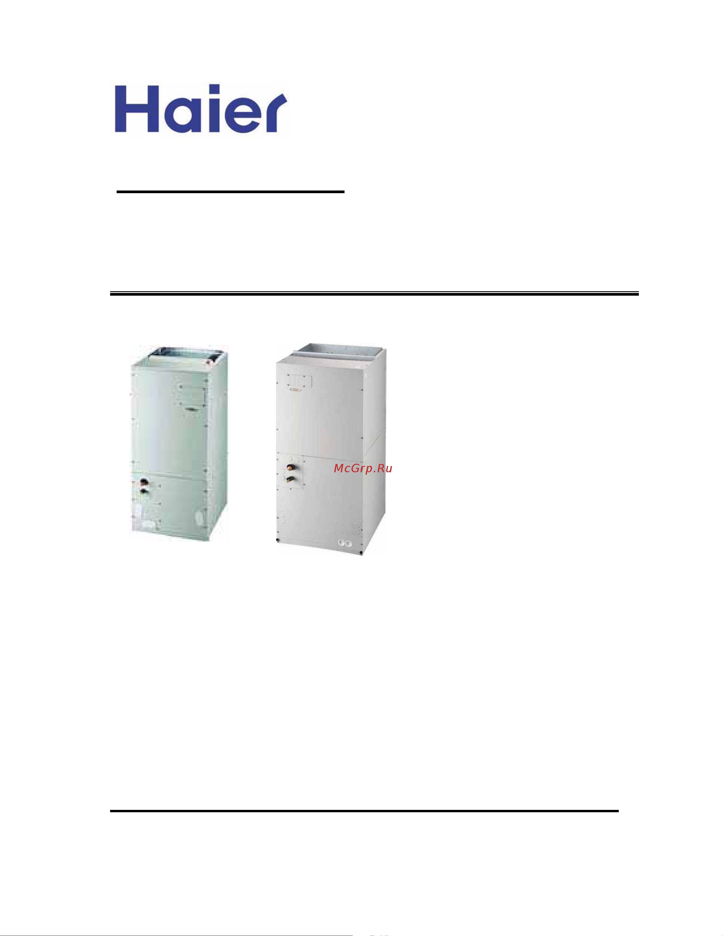
Models
Central Air Conditioning
zSplit-packaged design
z
zOptional electric heater
z
Convenient for installation and maintenance
z
Fully insulated and durable cabinet
Easily filter replacement
HB2400VD1M20
HB4800VD1M22
HB3600VD1M22
Manual code: SYJS-034-06REV.1 Edition: 2006-11-12
HB6000VD1M22(-E)
HB6000VD1M22
Содержание
- Central air conditioning 1
- Features 1
- Models 1
- Service manual 1
- Contents 2
- Air conditioning 3
- Central air conditioning model air handler hb d series 3
- Conditioning are manufactured to standards of quality and performance they are 13 seer seasonal 3
- Description of products features 3
- Engery efficiency ratio which meet or exceed the standards imposed by efficiency legislated and 3
- Example 3
- Needs less external protection while increasing the unit efficiency in cooling mode 3
- Nomenclature for model number 3
- System refers to the physical location of major air conditioning components the split system air 3
- Table 1 1 3
- Therefore represent both good value today and for years to come the current air conditioning system 3
- This manual discusses split central air conditioning and indoor coils split central air condition 3
- Use scroll and reciprocating compressors this gives the air conditioning a durable compressor which 3
- Application 5
- Cautio 5
- Central air conditioning model air handler hb d series 5
- Electrical control devices 5
- Safety precautions 5
- Central air conditioning model air handler hb d series 6
- Central air conditioning model air handler hb d series 7
- Installation instructions 7
- Central air conditioning model air handler hb d series 8
- Central air conditioning model air handler hb d series 9
- Central air conditioning model air handler hb d series 10
- Airflow orientation 11
- Central air conditioning model air handler hb d series 11
- A hammer and screw driver for each application making sure the primary and secondary drains are 12
- Air handler must be leveled and then pitched 1 4 toward drain side important drain pan must be 12
- And the secondary drain if used 12
- Bracket at the rear of the cavit 12
- Cal codes and practices l 12
- Central air conditioning model air handler hb d series 12
- Horizontal left hand installation 12
- If incorrect knockouts are removed water damage could occur 12
- Instructions follow steps below carefully to modify air handler for left hand 12
- Knockouts are located within the drain assemblies carefully remove only the correct knockouts using 12
- Left hand side 12
- Open and clear of burrs and debris remove secondary drain knockout only if this drain is required by 12
- Over torque screws snap in the drain cover on the right lower service panel 12
- Pan drain and also remove the plastic drain cover from the lower left access panel fig 6 5 12
- Plastic oval gasket on horizontal drain pan reinstall access panels and flowrator making sure not to 12
- Push the assembly completely to the rear of the cavity and assure it slips into channel 12
- Reinstall the a coil pan assembly in the air handler with the horizontal drain pan on the 12
- Relocate horizontal pan on the left hand side of the a coil assembly 12
- Remove j shape metal bracket holding coil pan in place slide out the a coil pan assembly from 12
- Replace the j shape metal bracket or brackets on the vertical drain pan and place the 12
- Tested for proper drainage by pouring water into the pan traps must be installed on both the primary drain 12
- The air handler can now be placed in its left horizontal position as shown in fig 6 the 12
- The air handler cavity with horizontal drain pan on the right side remove oval gasket from horizontal 12
- Warning 12
- With air handler in the vertical position remove all three access panels 12
- Central air conditioning model air handler hb d series 13
- Downflow instructions 13
- Note the m22 units can be installed as upflow discharge fig 6 6 13
- Central air conditioning model air handler hb d series 14
- Condensate removal 14
- Refrigerant tubing 14
- Warning the a coil contains 150 p s i g of air pressure 14
- Adequately insulated 15
- Air handler as indicated 15
- All pertinent information such as the rating plate included in the optional heat kit must be applied to the 15
- Central air conditioning model air handler hb d series 15
- Contain any of these materials 15
- Copper wire is recommended for all electrical connections 15
- Electrical code a disconnect means should be installed within sight of the unit as required by code 15
- Electrical connections 15
- Important the evaporator coil may have residual oils that could dissolve styrofoam and certain types of plastics therefore a removal pump or float switch must not 15
- Occur a trap must be installed between the unit and the condensate pump 15
- Table 6 1 electrical parameter 15
- The required electrical power supply information is located on and rating plate on the exterior of the unit 15
- The unit and the auxiliary drain pan must be adequately elevated to insure proper drainage 15
- The use of copper connections are recommended for all modification or field supplied accessories inside the air handler electrical section inside the control box 15
- The wiring diagram included in the heat kit must be placed over the wiring diagram on the air handler 15
- To the plastic drain pan during the soldering process all condensate drain lines and drain traps should be 15
- Use of a condensate removal pump may be necessary this condensate pump should have provisions for shutting off the control voltage should a blockage in the drain line or condensate pump failure 15
- When an optional heat kit is installed refer to the electrical requirements in that kit 15
- When copper tubing is uesed for the condensate line adequate caution must be taken to prevent damage 15
- Wiring selection must be in accordance with local codes or in absence of local code the national 15
- A means of strain relief to protect the entry block wire connection 16
- Central air conditioning model air handler hb d series 16
- Electric control function for air handlers 16
- Function description 16
- Port definition 16
- When an optional electric heat kit is installed refer to the electrical requirements for that kit the ampacity and over current protection shown above is onl y for hb air handlers installed without a heat ki 16
- Air handler wiring diagram 17
- Bcr blower control relay bcap run capacitor blower motor btd blower time delay ibm indoor blower motor tran transformer 230 208 selectable 17
- Bk black bl blue gy gray br brown gr green or orange pu purple rd red vi violet wh white yl yellow 17
- Central air conditioning model air handler hb d series 17
- Color codes 17
- Component codes 17
- Confirm system selection optional components may be field or factory installed 2 for proper system operation consult indoor unit and outdoor unit installation instructions to confirm system match up and blower speed selection if the motor have only one capacitor wire connect com line to capacitor 3 indoor unit shipped without optional electric heater kit to install optional heater kit remove power pig tail up to 9 pin plug install heater kit and connect with mating 9 pin plug run system power connections directly to electric heater kit power terminals consult heater kit installation instructions for complete details 17
- Ha cool off 17
- Line voltage factory standard field installed optional low voltage factory standard field installed optional 17
- Use copper conductors only warning cabinet must be permanently grounded and all wiring to conform to i e c n e c c e c c l c and local codes as applicable replacement wire must be the same gage and insulation type as original wire 17
- Wiring diagram 17
- Sincere forever 18
Похожие устройства
- Haier HB6000VD1M22-E Сервис мануал
- Haier HC18A1VAR Руководство по эксплуатации
- Haier HC24A1VAR Руководство по эксплуатации
- Haier HC30A1VAR Руководство по эксплуатации
- Haier HC36A1VAS Руководство по эксплуатации
- Haier HC42A1VAR Руководство по эксплуатации
- Haier HC48A1VAR Руководство по эксплуатации
- Haier HC60A1VAR Руководство по эксплуатации
- Haier HC18A1VAR Сервис мануал
- Haier HC24A1VAR Сервис мануал
- Haier HC30A1VAR Сервис мануал
- Haier HC36A1VAS Сервис мануал
- Haier HC42A1VAR Сервис мануал
- Haier HC48A1VAR Сервис мануал
- Haier HC60A1VAR Сервис мануал
- Haier HB2400VA1M20 Инструкция по эксплуатации
- Haier HB2400VC1M20 Инструкция по эксплуатации
- Haier HB3000VA1M20 Инструкция по эксплуатации
- Haier HB3600VA1M20 Инструкция по эксплуатации
- Haier HC18C1VAR Руководство по эксплуатации