
Aten KX9970R Краткое руководство по установке онлайн
KX9970 5K DisplayPort KVM-удлинитель с доступом по IP
www.aten.com
A
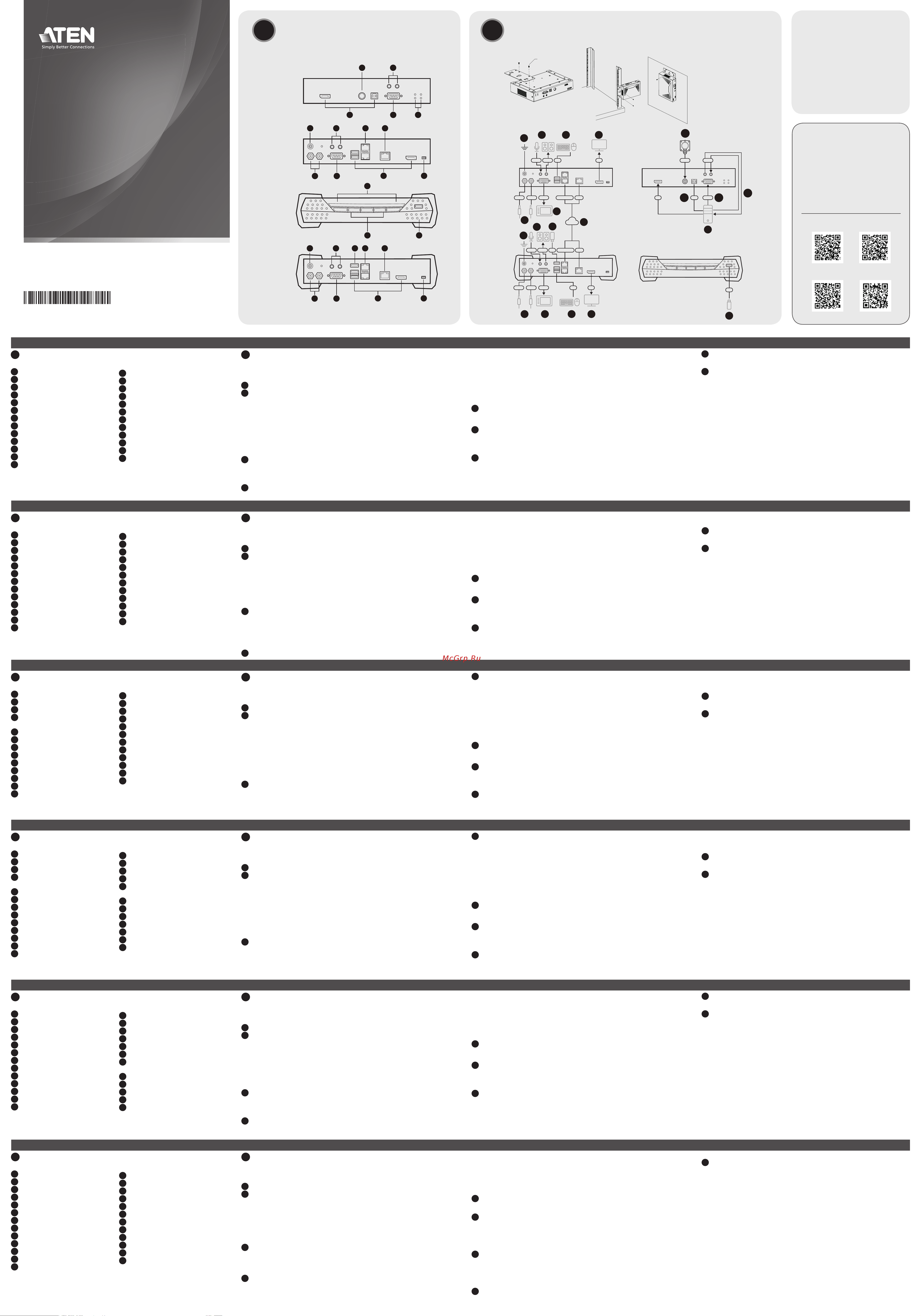
Основные элементы
KX9970T
1
Порты KVM
2
Порт управления доступом
3
Аудиоразъемы (ПК/сервер)
4
Послед. порт RS-232 (ПК/сервер)
5
Индикаторы статуса и питания
6
Контакт заземления
7
Разъемы питания (пост.тока)
8
Аудиоразъемы (консоль)
9
Послед. порт устройства RS-232
10
Слоты SFP+
11
Порт LAN 10 Гб
12
Порты консоли
13
Переключатель функций
B
Установка
Присоединение кронштейна
Для монтажа KX9970T в стойке или на стене сначала прикрепите монтажный
кронштейн, выполнив следующие действия.
1
Выкрутите винты с боковой стороны устройства, как показано на рисунке.
2
Винтами, извлеченными в шаге 1, прикрепите монтажный кронштейн к нижней
части устройства, как показано на рисунке.
Монтаж в стойке
Привинтите устройство к стойке в любом удобном месте.
Монтаж на стене
Используйте центральное отверстие, чтобы прикрепить кронштейн к стене.
Подключение KX9970T
1
Заземлите устройство, подсоединив один конец заземляющего провода к
контакту заземления, а другой конец к заземленному объекту.
Примечание: Не пропускайте это действие. Надлежащее заземление
помогает защитить устройство от повреждений, вызванных перепадами
напряжения и статическим электричеством.
2
Только для KX9970T. Выполните следующие действия:
a. С помощью прилагаемых кабелей DisplayPort и «USB Type-A—Type-B»
подсоедините KVM-порты устройства к видео и USB-портам управляемого
ПК/сервера.
b. (Дополнительно) Для передачи аудиосигнала подключите передние
аудиопорты устройства к аудиопортам ПК/сервера.
c. (Дополнительно) Для управления последовательными устройствами
подключите разъем RS-232 на данном устройстве к последовательному
порту ПК/сервера.
d. (Дополнительно) Для использования кнопки 2XRT-0015G подключите его к
порту PS/2 для управления доступом на устройстве.
3
Для использования консольного управления подключите к портам консоли
устройства USB-клавиатуру и мыши, монитор с DisplayPort, микрофон,
динамики и/или последовательную консоль.
4
(Дополнительно) Только для KX9970R. Чтобы использовать до 2-х
периферийных USB-устройств, подключите их к 2-м периферийным
USB-портам на устройстве.
Примечание: Периферийные USB-порты совместимы с изохронными
конечными точками и, таким образом, поддерживают потоковую передачу
видео и аудио.
5
Для подачи питания (и включения устройства) подключите прилагаемый
адаптер питания к источнику питания пер. тока, а затем вставьте кабель
адаптера в 1 из 2-х гнезд питания (пост. тока) на устройстве.
Примечание: Для организации резервного питания можно подсоединить 2-ой
адаптер питания к другому источнику питания пер. тока, подключив второй
кабель адаптера в другое гнездо питания (пост. тока) на устройстве.
6
Для KX9970T. Включите питание ПК/сервера.
KX9970R
1
Индикаторы статуса и питания
2
Функциональные кнопки
3
Периферийный USB-порт
4
Контакт заземления
5
Разъемы питания (пост.тока)
6
Аудиоразъемы (консоль)
7
Послед. порт устройства RS-232
8
Периферийный USB-порт
9
Слоты SFP+
10
Порт LAN 10 Гб
11
Порты консоли
12
Переключатель функций
Соединение между KX9970T — KX9970R
7
Передатчик и приемник KX9970 (Tx/Rx) оснащены двумя слотами SFP+ и
одним портом LAN 10 Гб. Для передачи управляющих сигналов от KX9970T
к KX9970R следует соединить их с помощью оптоволоконного кабеля и/или
кабеля Cat 5e/6 одним из следующих способов:
• С помощью прямого соединения слотов SFP+ и/или портов LAN на обоих
устройствах.
• С помощью подсоединения к одной сети через слоты SFP+ и/или порты LAN на
обоих устройствах.
Примечание: Для управления всеми KX9970, подключенными к одной сети,
может использоваться CCKM – специальное ПО от ATEN для матричного
управления устройствами KVM over IP.
Экранное меню настроек
Настройка приемника и передатчика осуществляется из экранного меню
приемника. Сведения о настройке параметров с помощью экранного меню
приведены в руководстве пользователя устройств серии KE/KX (которое можно
загрузить на сайте www.aten.com).
KX9970 5K Estensore DisplayPort KVM su IP
www.aten.com
A
Panoramica dell'Hardware
KX9970T
1
Porte KVM
2
porta di accesso di controllo
3
porte audio (PC / server)
4
porta seriale RS-232 (PC / server)
5
led di accensione e di stato
6
terminale di messa a terra
7
connettori di alimentazione CC
8
porte audio (console)
9
porta del dispositivo seriale RS-232
10
slot SFP+
11
porta LAN da 10 Gb
12
porte console
13
commutatore di funzioni
B
Installazione
Montare la staffa
Per montare il KX9970T su un telaio o su una parete, prima fi ssare la staffa di
supporto. Seguire queste istruzioni.
1
Svitare le viti dal lato dell’unità, come mostrato.
2
Usare le viti del punto 1 per fi ssare la staffa di montaggio sul fondo
dell’unità, come mostrato.
Montaggio sostegno
Fissare l’unità avvitando la staffa nella posizione più comoda del sostegno.
Montaggio a parete
Usa il foro centrale per fi ssare la staffa su una superfi cie stabile.
Collegare il KX9970T
1
Utilizzare un fi lo di messa a terra per mettere a terra l'unità collegando
un'estremità al morsetto di messa a terra e l'altra estremità ad un oggetto idoneo.
Nota: Non saltare questo passaggio. La messa a terra adeguata aiuta a
prevenire danni all'unità dovuti a sovraccarico o elettricità statica.
2
Solo per il KX9970T fare come segue:
a. Usare il cavo DisplayPort e il cavo USB da tipo A a tipo B fornito per
connettere le porte KVM dell’unità alle porte video e USB del PC / server
che si sta controllando.
b. (Facoltativo) Per la trasmissione audio, collegare le porte audio anteriori
dell’unità a quelle del PC / server.
c. (Facoltativo) Per controllare dispositivi seriali, collegare la porta seriale RS-
232 frontale dell’unità a quella del PC / server.
d. (Facoltativo) Per usare un 2XRT-0015G, collegarlo alla porta di accesso di
controllo PS/2 dell’unità.
3
Per usare una console collegare le porte per console dell’unità a una
tastiera e mouse USB, a uno schermo, microfono e altoparlanti DisplayPort,
e/o a un dispositivo di console seriale, secondo necessità.
4
(Facoltativo) Solo per il KX9970R, per usare periferiche USB, collegarne al
massimo due alle due porte USB periferiche dell’unità.
Nota: Le porte periferiche USB sono compatibili con endpoint isocroni, e
quindi supportano streaming audio e video.
5
Alimentare l'unità, quindi accenderla, collegando l'adattatore di
alimentazione fornito a una fonte di alimentazione CA e collegando il cavo
a una delle due prese di alimentazione CC dell'unità.
Nota: Per avere alimentazione ridondante, si può anche collegare un
secondo adattatore CA a un’altra presa di corrente, e collegarne l’altro
capo alla seconda presa CC dell’unità.
KX9970R
1
led di accensione e di stato
2
pulsanti di funzionamento
3
porta periferica USB
4
terminale di messa a terra
5
connettori di alimentazione CC
6
porte audio (console)
7
porta del dispositivo seriale
RS-232
8
porta periferica USB
9
slot SFP+
10
porta LAN da 10 Gb
11
porte console
12
commutatore di funzioni
6
Per il KX9970T, accendere il PC / server.
Estendere il KX9970T — KX9970R
7
Ciascun KX9970 (Tx / Rx) è dotato di due slot SFP+ e di una porta LAN da
10 Gb. Per estendere il controllo da un KX9970T a un KX9970R, si può
usare la fi bra ottica e/o cavi di categoria 5e/6 secondo uno dei seguenti
metodi:
• Collegarli direttamente, da punto a punto, tramite le slot SFP+ e/o le porte
LAN.
• Collegarli alla stessa rete tramite le loro slot SFP+ e/o le porte LAN.
Nota: Tutti i KX9970 installati nella stessa rete si possono gestire con CCKM,
il software di ATEN dedicato per la gestione della matrice KVM over IP.
Opzioni OSD
Puoi confi gurare entrambe le unità, trasmettitore e ricevitore, dal menù OSD
sul ricevitore. Per la confi gurazione dell’OSD, vedere il manuale utente KE/KX
(che si può scaricare da www.aten.com).
Extensor KX9970 5K DisplayPort KVM sobre IP
www.aten.com
A
Vista general del hardware
KX9970T
1
Puertos KVM
2
puerto de control de acceso
3
puertos de audio (PC / servidor)
4
puerto de serie RS-232 (PC /
servidor)
5
LED de alimentación y estado
6
terminal de conexión a tierra
7
Conectores de alimentación de CC
8
puertos de audio (consola)
9
Puerto de dispositivo serie RS-232
10
Ranuras SFP+
11
Puerto LAN de 10 Gb
12
Puertos de consola
13
conmutador de función
B
Instalación
Accesorio de soporte
Para instalar el KX9970T en un bastidor o en la pared, primero fi je el soporte
de montaje haciendo lo siguiente.
1
Desatornille los tornillos del lado de la unidad tal y como se muestra.
2
Use los tornillos del paso 1 para asegurar el soporte de montaje a la parte
inferior de la unidad tal y como se muestra.
Montaje en bastidor
Asegure la unidad atornillando el soporte en una ubicación conveniente del
bastidor.
Montaje en pared
Use el orifi cio central para atornillar el soporte en una superfi cie de pared segura.
Conectar KX9970T
1
Utilice un cable de tierra para conectar la unidad a tierra conectando un
extremo al terminal de tierra y el otro extremo a un objeto conectado a
tierra correctamente.
Nota: No omita este paso. La conexión a tierra adecuada ayuda a evitar
daños en la unidad por sobrecargas de energía o electricidad estática.
2
Solo para KX9970T, haga lo siguiente:
a. Usando el cable DisplayPort y el cable USB Tipo-A a Tipo-B provisto,
conecte los puertos KVM de la unidad a los puertos de vídeo y USB de la
PC / servidor que está controlando.
b. (Opcional) Para la transmisión de audio, conecte los puertos de audio
frontales de la unidad a los de la PC / servidor.
c. (Opcional) Para el control de dispositivos seriales, conecte el puerto serial
RS-232 frontal de la unidad al de la PC / servidor.
d. (Opcional) Para usar un 2XRT-0015G, conéctelo al puerto de control de
acceso PS/2 de la unidad.
3
Para el funcionamiento de la consola, conecte los puertos de la consola
de la unidad a un teclado y ratón USB, monitor DisplayPort, micrófono,
altavoces y/o dispositivo de consola serie, según sea necesario.
4
(Opcional) Solo para KX9970R; para usar dispositivos USB periféricos,
conecte hasta 2 dispositivos a los 2 puertos periféricos USB de la unidad.
Nota: Los puertos periféricos USB son compatibles con puntos fi nales
isócronos y, por lo tanto, admiten transmisión de vídeo y audio.
5
Conecte la unidad a la corriente, encendiéndola, enchufando el adaptador de
corriente proporcionado en una fuente de alimentación de CA y enchufando su
cable en 1 de los 2 enchufes de alimentación de CC de la unidad.
KX9970R
1
LED de alimentación y estado
2
pulsadores de operación
3
Puerto periférico USB
4
terminal de conexión a tierra
5
Conectores de alimentación de
CC
6
puertos de audio (consola)
7
Puerto de dispositivo serie RS-232
8
Puerto periférico USB
9
Ranuras SFP+
10
Puerto LAN de 10 Gb
11
Puertos de consola
12
conmutador de función
Nota: Para redundancia de alimentación, opcionalmente conecte un segundo
adaptador de alimentación a otra fuente de alimentación de CA y conecte su
otro extremo al segundo conector de alimentación de CC de la unidad.
6
Para KX9970T, encienda la PC / servidor.
Extensión KX9970T — KX9970R
7
Cada KX9970 (Tx/Rx) está equipado con dos ranuras SFP+ y un puerto
LAN de 10 Gb. Para extender el control de un KX9970T a un KX9970R,
se puede establecer usando cables de fi bra óptica y/o Cat 5e/6 a través de
uno de los siguientes métodos:
• Conéctelos directamente, punto a punto, a través de sus ranuras SFP+ y/o
puerto LAN.
• Conéctelos a la misma red a través de sus ranuras SFP+ y/o puerto LAN.
Nota: Todos los KX9970 instalados en la misma red se pueden gestionar
mediante CCKM, el software de gestión de matrices KVM over IP exclusivo de
ATEN.
Opciones del OSD
Tanto las unidades transmisoras como las receptoras se pueden confi gurar
desde el menú OSD del receptor. Para la confi guración de OSD, consulte el
manual de usuario de KE/KX (descargable en www.aten.com).
KX9970 5K DisplayPort KVM over IP Extender
www.aten.com
A
Hardware Übersicht
KX9970T
1
KVM Anschlüsse
2
Zugangskontrollanschluss
3
Audioanschlüsse (PC / Server)
4
Serieller RS-232 Anschluss (PC /
Server)
5
Stromversorgung & Status LEDs
6
Erdungsanschluss
7
DC Strombuchsen
8
Audioanschlüsse (Konsole)
9
Serieller RS-232 Port
10
SFP+ Steckplätze
11
10 Gb LAN Port
12
Konsolenanschlüsse
13
Funktionsschalter
B
Installation
Anbringen der Halterung
Um den KX9970T in einem Rack oder an einer Wand zu installieren, müssen
Sie zunächst die Montagehalterung wie folgt anbringen.
1
Lösen Sie die Schrauben an der Seite des Geräts wie abgebildet.
2
Verwenden Sie die Schrauben aus Schritt 1, um die Montagehalterung wie
abgebildet an der Unterseite des Extenders zu befestigen.
Rack-Montage
Befestigen Sie das Gerät, indem Sie die Halterung an einer geeigneten Stelle
des Racks anschrauben.
Wandmontage
Verwenden Sie die mittlere Öffnung, um die Halterung an eine sichere
Wandfl äche zu schrauben.
Anschluss des KX9970T
1
Verwenden Sie ein Erdungskabel, um das Gerät zu erden, indem Sie ein
Ende mit der Erdungsklemme und das andere Ende mit einem geeigneten
geerdeten Objekt verbinden.
Hinweis: Lassen Sie diesen Schritt nicht aus. Eine angemessene Erdung
hilft bei der Verhinderung von Geräteschäden durch Spannungsspitzen
oder statische Elektrizität.
2
Gehen Sie nur beim KX9970T wie folgt vor:
a. Verbinden Sie die KVM Anschlüsse des Geräts über das mitgelieferte
DisplayPort Kabel und das USB Typ-A auf Typ-B Kabel mit den Video-
und USB-Anschlüssen des PCs/Servers, den Sie steuern möchten.
b. (Optional) Für die Audioübertragung verbinden Sie die vorderen
Audioanschlüsse des Geräts mit denen des PCs/Servers.
c. (Optional) Für die Steuerung serieller Geräte verbinden Sie den vorderen
seriellen RS-232 Anschluss des Geräts mit dem des PCs/Servers.
d. (Optional) Um eine 2XRT-0015G zu verwenden, schließen Sie sie an den
PS/2 Zugangskontrollanschluss des Geräts an.
3
Für den Konsolenbetrieb schließen Sie die Konsolenanschlüsse des Geräts
je nach Bedarf an eine USB-Tastatur und Maus, einen DisplayPort Monitor,
ein Mikrofon, Lautsprecher und/oder ein serielles Konsolengerät an.
4
(Optional) Nur beim KX9970R können Sie bis zu 2 USB Peripheriegeräte an
die 2 USB Peripherieanschlüsse des Geräts anschließen.
Hinweis: Die USB-Peripherieanschlüsse sind mit isochronen Endpunkten
kompatibel und unterstützen daher Video- und Audiostreaming.
5
Versorgen Sie das Gerät mit Strom und schalten Sie es ein, indem Sie das
mitgelieferte Netzteil an eine Wechselstromquelle anschließen und sein Kabel in
1 der 2 DC Strombuchsen des Geräts stecken.
KX9970R
1
Stromversorgung & Status LEDs
2
Bedienungstasten
3
USB-Peripherieport
4
Erdungsanschluss
5
DC Strombuchsen
6
Audioanschlüsse (Konsole)
7
Serieller RS-232 Port
8
USB-Peripherieport
9
SFP+ Steckplätze
10
10 Gb LAN Port
11
Konsolenanschlüsse
12
Funktionsschalter
Hinweis: Für eine redundante Stromversorgung können Sie optional ein
zweites Netzteil an eine andere Wechselstromquelle anschließen und dessen
anderes Ende mit der zweiten DC Strombuchse des Geräts verbinden.
6
Schalten Sie beim KX9970T den PC/Server ein.
Erweiterung des KX9970T — KX9970R
7
Jeder KX9970 (Tx / Rx) ist mit zwei SFP+ Steckplätzen und einem 10-Gb
LAN Port ausgestattet. Eine Erweiterung der Steuerung von einem KX9970T
zu einem KX9970R kann mit Glasfaser- und/oder Cat 5e/6-Kabeln über
eine der folgenden Methoden hergestellt werden:
• Verbinden Sie sie direkt, Punkt-zu-Punkt, über ihre SFP+ Steckplätze und/
oder den LAN-Port.
• Verbinden Sie sie über ihre SFP+ Steckplätze und/oder den LAN-Port mit
demselben Netzwerk.
Hinweis: Alle im selben Netzwerk installierten KX9970 können mit CCKM,
der speziellen KVM over IP Matrix Management Software von ATEN, verwaltet
werden.
OSD-Optionen
Sowohl die Sende- als auch die Empfängereinheiten werden über das OSD-
Menü am Empfänger konfi guriert. Die OSD-Konfi guration fi nden Sie im KE/KX
Benutzerhandbuch (herunterladbar unter www.aten.com).
Extenseur 5K DisplayPort KVM sur IP KX9970
www.aten.com
A
Survol du matériel
KX9970T
1
Ports KVM
2
port access control
3
ports audio (PC / serveur)
4
port série RS-232 (PC / serveur)
5
LED d'alimentation et d'état
6
terminal de terre
7
prises d'alimentation CC
8
ports audio (console)
9
port de périphérique série RS-232
10
logements SFP+
11
port LAN 10 Gb
12
ports de console
13
commutateur de fonction
B
Installation
Fixation du support
Pour installer KX9970T sur un rack ou un mur, fi xez d'abord le support de
montage en procédant comme suit.
1
Dévissez les vis sur le côté de l'unité comme indiqué.
2
Utilisez les vis de l'étape 1 pour fi xer le support de montage au bas de
l'unité, comme illustré.
Montage sur étagère
Fixez l'unité en vissant le support à un endroit approprié du rack.
Montage mural
Utilisez le trou central pour visser le bras sur une surface murale sécurisée.
Connexion du KX9970T
1
Utilisez un câble de terre pour relier l'unité à terre en connectant une
extrémité à la borne de terre et l'autre extrémité à un objet correctement
relié à terre.
Remarque : N'ignorez pas cette étape. Une mise à terre appropriée permet
d'éviter que l'appareil ne soit endommagé par des surtensions ou de
l'électricité statique.
2
Pour le KX9970T uniquement, procédez comme suit :
a. À l'aide du câble DisplayPort et du câble USB Type-A vers Type-B fournis,
connectez les ports KVM de l'unité aux ports vidéo et USB du PC /
serveur que vous contrôlez.
b. (Facultatif) Pour la transmission audio, connectez les ports audio avant
de l'unité à ceux du PC / serveur.
c. (Facultatif) Pour le contrôle de périphériques série, connectez le port
série RS-232 avant de l'unité à celui du PC / serveur.
d. (Facultatif) Pour utiliser un 2XRT-0015G, connectez-le au port access
control PS/2 de l'unité.
3
Pour le fonctionnement en mode console, connectez les ports de console de
l'appareil à un clavier et une souris USB, un écran DisplayPort, un microphone,
des haut-parleurs et/ou un dispositif de console série, selon les besoins.
4
(Facultatif) Pour le KX9970R uniquement, pour utiliser des périphériques
USB, connectez-en jusqu'à 2 aux 2 ports périphériques USB de l'unité.
Remarque : Les ports périphériques USB sont compatibles avec les points de
terminaison isochrones et prennent donc en charge la diffusion vidéo et audio.
5
Connectez l'unité à l'alimentation, et mettez-la sous tension, en branchant
l'adaptateur d'alimentation fourni sur une source d'alimentation CA et en
branchant son câble sur 1 des 2 prises d'alimentation CC de l'unité.
Remarque : Pour une redondance de l'alimentation, vous pouvez brancher
un deuxième adaptateur d'alimentation sur une autre source d'alimentation
KX9970R
1
LED d'alimentation et d'état
2
boutons de commande
3
port périphérique USB
4
terminal de terre
5
prises d'alimentation CC
6
ports audio (console)
7
port de périphérique série RS-232
8
port périphérique USB
9
logements SFP+
10
port LAN 10 Gb
11
ports de console
12
commutateur de fonction
CA et brancher son autre extrémité sur la deuxième prise d'alimentation
CC de l'unité.
6
Pour KX9970T, mettez le PC / serveur sous tension.
Extension de KX9970T — KX9970R
7
Chaque KX9970 (Tx / Rx) est équipé de deux logements SFP+ et d'un port
LAN 10-Gb. L’extension du contrôle d'un KX9970T à un KX9970R peut être
établie en utilisant des câbles à fi bre optique et/ou Cat 5e/6 par l'une des
méthodes suivantes :
• Connectez-les directement, point à point, via leurs logements SFP+ et/ou leur
port LAN.
• Connectez-les au même réseau via leurs logements SFP+ et/ou leur port LAN.
Remarque : Tous les KX9970 installés dans le même réseau peuvent être
gérés à l'aide de CCKM, le logiciel de gestion de matrice KVM over IP dédié
d'ATEN.
Options OSD
Le transmetteur et le récepteur peuvent être confi gurés depuis le menu OSD
sur le récepteur. Pour la confi guration OSD, consultez le manuel de l’utilisateur
du KE/KX (téléchargeable à www.aten.com).
B
Installation
© Copyright 2022 ATEN
®
International Co. Ltd.
ATEN and the ATEN logo are registered trademarks of ATEN International Co., Ltd.
All rights reserved. All other trademarks are the property of their respective owners.
Part No. PAPE-1223-W70G Released: 06/2022
5K DisplayPort KVM over IP Extender
Quick Start Guide
KX9970
KX9970 5K DisplayPort KVM over IP Extender
www.aten.com
A
Hardware Overview
Package Contents
1 KX9970T 5K DisplayPort KVM
over IP Transmitter / KX9970R 5K
DisplayPort KVM over IP Receiver
1 DisplayPort cable (KX9970T only)
1 USB Type-A to Type-B cable
(KX9970T only)
1 mounting kit (KX9970T only)
1 power adapter
1 foot pad set (4 pcs)
1 user instructions
Support and Documentation Notice
All information, documentation, fi rmware,
software utilities, and specifi cations
contained in this package are subject to
change without prior notifi cation by the
manufacturer.
To reduce the environmental impact of
our products, ATEN documentation and
software can be found online at
http://www.aten.com/download/
Technical Support
www.aten.com/support
Scan for more information
ATEN Website ATEN Website
User Manual ATEN Matrix Link
Wall Mount
M3 x 6
Bracket
Attachment
Rack Mount
A
Hardware Overview
KX9970T
1
KVM ports
2
access control port
3
audio ports (PC / server)
4
RS-232 serial port (PC / server)
5
power & status LEDs
6
grounding terminal
7
DC power jacks
8
audio ports (console)
9
RS-232 serial device port
10
SFP+ slots
11
10 Gb LAN port
12
console ports
13
function switch
B
Installation
Bracket Attachment
To install KX9970T onto a rack or wall, fi rst, attach the mounting bracket by
doing the following.
1
Unscrew the screws from the side of the unit as shown.
2
Use the screws from step 1 to secure the mounting bracket to the bottom
of the unit as shown.
Rack Mount
Secure the unit by screwing the bracket onto a convenient location on the
rack.
Wall Mount
Use the center hole to screw the bracket onto a secure wall surface.
Connecting KX9970T
1
Use a grounding wire to ground the unit by connecting one end to the
grounding terminal and the other end to a suitable grounded object.
Note: Do not omit this step. Proper grounding helps prevent damage to
the unit from power surges or static electricity.
2
For KX9970T only, do the following:
a. Using the DisplayPort cable and USB Type-A to Type-B cable provided,
connect the unit’s KVM ports to the video and USB ports of the PC /
server you are controlling.
b. (Optional) For audio transmission, connect the unit’s front audio ports to
those of the PC / server.
c. (Optional) For control of serial devices, connect the unit’s front RS-232
serial port to that of the PC / server.
d. (Optional) To use a 2XRT-0015G, connect it to the unit’s PS/2 access
control port.
3
For console operation, connect the unit’s console ports to a USB keyboard
& mouse, DisplayPort monitor, microphone, speakers, and/or serial console
device as needed.
4
(Optional) For KX9970R only, to use peripheral USB devices, connect up to
2 to the unit’s 2 USB peripheral ports.
Note: The USB peripheral ports are isochronous endpoints compatible and
thus support video and audio streaming.
5
Connect the unit to power, thereby turning it on, by plugging the power
adapter provided into an AC power source and plugging its cable into 1 of
the unit’s 2 DC power jacks.
Note: For power redundancy, optionally connect a second power adapter
into another AC power source and connect its other end to the unit’s
second DC power jack.
KX9970R
1
power & status LEDs
2
operation pushbuttons
3
USB peripheral port
4
grounding terminal
5
DC power jacks
6
audio ports (console)
7
RS-232 serial device port
8
USB peripheral port
9
SFP+ slots
10
10 Gb LAN port
11
console ports
12
function switch
6
For KX9970T, power on the PC / server.
Extending KX9970T — KX9970R
7
Every KX9970 (Tx / Rx) is equipped with two SFP+ slots and one 10-Gb
LAN port. For extending control from a KX9970T to a KX9970R, it can be
established using fi ber-optic and/or Cat 5e/6 cables through one of the
following methods:
• Connect them directly, point-to-point, via their SFP+ slots and/or LAN port.
• Connect them to the same network via their SFP+ slots and/or LAN port.
Note: All KX9970 installed within the same network can be managed using
CCKM, ATEN’s dedicated KVM over IP Matrix Manager.
OSD Options
Both the transmitter and receiver units can be confi gured from the OSD
menu on the receiver. For OSD confi guration, refer to the KE/KX user manual
(downloadable at www.aten.com).
KX9970T KX9970R
*Only for iPadOS 9.0
or later
KX9970T (Front)
KX9970T (Rear)
KX9970R (Front)
KX9970R (Rear)
2
10 6 11
3
8
1
5
9
3
7
1
2
12 13
4 8 9 106
75
11 12
4
1
1
3
5 3 3 3
3 3
3
3
4
4
5
7
6
2-d
2-b
2-a 2-c
Audio
Audio
Network
Optical Fiber RJ-45
Optical Fiber RJ-45USB
KX9970T
(Front)
2XRT-0015G
KX9970T
(Rear)
KX9970R
(Front)
KX9970R
(Rear)
Power RS-232 DP
DP
Power
Power RS-232 RS-232Power
USBAudio Audio
USB
USB
AudioPS/2
DP USB
Note: These placement
options only apply to
KX9970T
Содержание
- Hardware overview 1
- Hardware übersicht 1
- Instalación 1
- Installation 1
- Installazione 1
- K displayport kvm over ip extender quick start guide 1
- Kx9970 1
- Opciones del osd 1
- Options osd 1
- Opzioni osd 1
- Osd optionen 1
- Osd options 1
- Panoramica dell hardware 1
- Survol du matériel 1
- Vista general del hardware 1
- Основные элементы 1
- Установка 1
- Экранное меню настроек 1
- Braket parçası 2
- Donanıma genel bakış 2
- Duvara montaj 2
- Fixação do suporte 2
- Instalare 2
- Instalação 2
- Kurulum 2
- Kx9970r 2
- Kx9970t 2
- Mocowanie wspornika 2
- Montagem em bastidor 2
- Montagem na parede 2
- Montarea pe perete 2
- Montarea pe rack 2
- Montaż 2
- Montaż na stelażu 2
- Montaż na ścianie 2
- Opcje osd 2
- Opções osd 2
- Opțiuni osd 2
- Osd seçenekleri 2
- Osd オプション 2
- Osd 选项 2
- Osd 選項 2
- Osd 옵션 2
- Prezentare hardware 2
- Prinderea suportului 2
- Przegląd sprzętu 2
- Rafa montaj 2
- Vista geral do hardware 2
- Встановлення 2
- Огляд обладнання 2
- Опції osd 2
- Прикріплення кронштейна 2
- Підвішення на стійку 2
- Підвішення на стіну 2
- ウォールマウント 2
- セットアップ 2
- ブラケットの取り付け 2
- ラックマウント 2
- 壁挂安装 2
- 壁掛安裝 2
- 安装 2
- 安裝 2
- 托架安装 2
- 支架安裝 2
- 机架安装 2
- 機架安裝 2
- 硬件概览 2
- 硬體檢視 2
- 製品各部名称 2
- 랙 마운트 2
- 브래킷 부착 2
- 설치 2
- 월 마운트 2
- 하드웨어 개요 2
Похожие устройства
- Aten KX9970R Руководство пользователя
- Aten KX9970FT Краткое руководство по установке
- Aten KX9970FT Руководство пользователя
- Aten KX9970FR Краткое руководство по установке
- Aten KX9970FR Руководство пользователя
- Aten KE6910ATC Руководство пользователя
- Aten KE6910ATC Краткое руководство по установке
- Aten KE6920ATC Руководство пользователя
- Aten KE9950ATC Руководство пользователя
- Aten KE6940AiT Краткое руководство по установке
- Aten KE6940AiT Руководство пользователя
- Aten KE6900AiT Краткое руководство по установке
- Aten KE6900AiT Руководство пользователя
- Aten KE6922R Краткое руководство по установке
- Aten KE6922R Руководство пользователя
- Aten KE6922T Краткое руководство по установке
- Aten KE6922T Руководство пользователя
- Aten KE6920R Краткое руководство по установке
- Aten KE6920R Руководство пользователя
- Aten KE6920T Краткое руководство по установке