
Aten KE9900ST Краткое руководство по установке онлайн
Требования
Приемник ATEN
• Повторитель(приемник)KVM-по-IPсерииKE
A
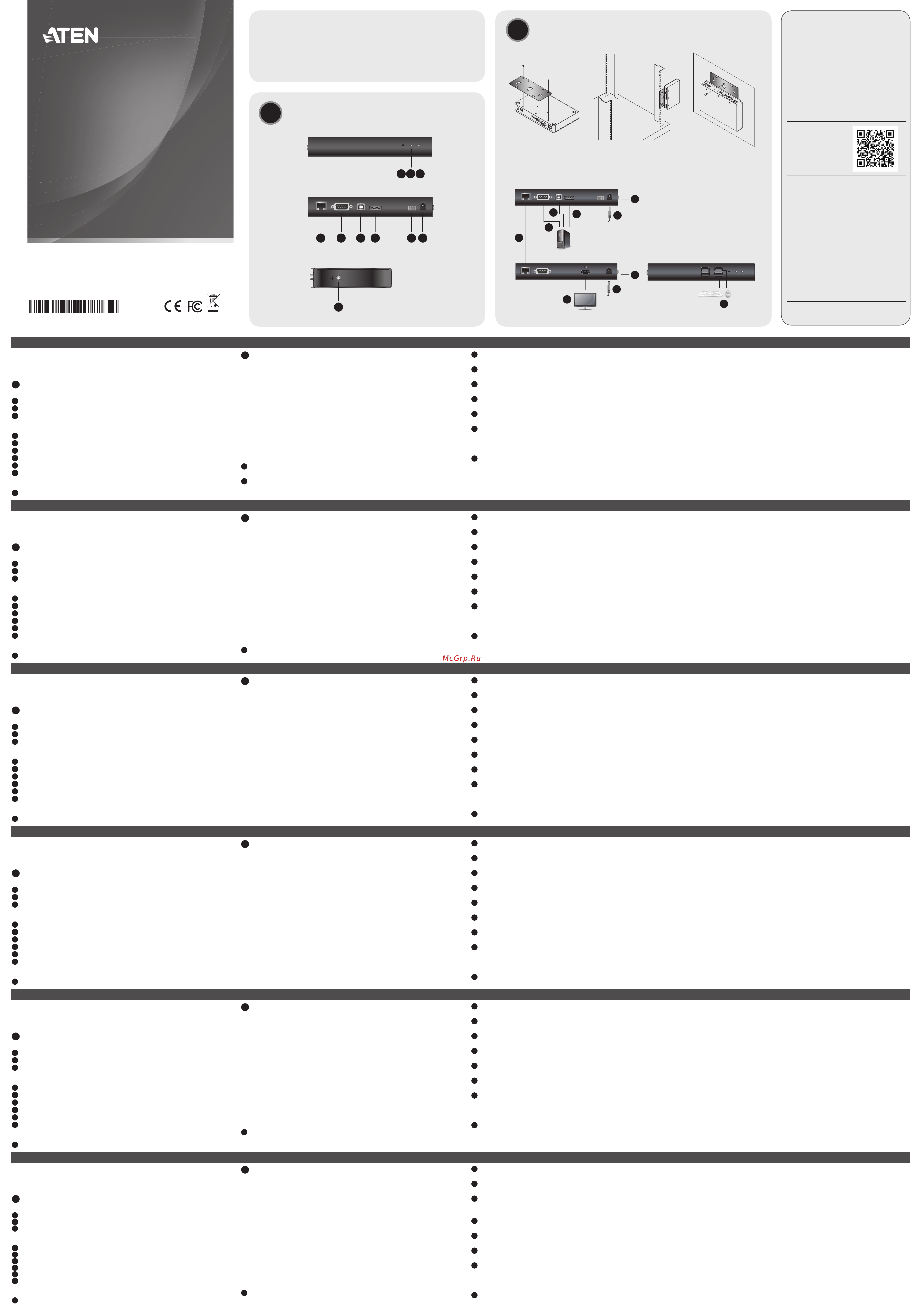
Обзор оборудования
Передняя панель KE9900ST
1
Кнопкасброса(утопленнаякнопка)
2
ИндикаторLAN
3
Индикаторпитания
Задняя панель KE9900ST
4
ПортLAN
5
ПортRS-232
6
ПортUSBType-B
7
ВходDisplayPort
8
3-контактныйклеммник(входпитания)
9
Разъёмпитания
Боковая панель KE9900ST
10
Заземляющийконтакт
B
Установка оборудования
Монтаж в стойке
1.Винтамиизмонтажногокомплектаприкрепитемонтажныйкронштейн
книжнейчастиустройства(какпоказанонасхемевыше).
2.Привинтитемонтажныйкронштейнкстойкевлюбомудобномместе.
Примечание. ДлямонтажаKE9900STследуетиспользоватьКомплект
стоечногомонтажаповторителейATENVE-RMK1U.
Комплектможноприобрестиуместногодилеракомпании.
Монтаж на стене
1.Винтамиизмонтажногокомплектаприкрепитемонтажныйкронштейн
книжнейчастиустройства(какпоказанонасхемевыше).
2.Дляприкрепленияустройствакстене,ввернитеболтвстенучерез
центральноеотверстиедляболтавмонтажномкронштейне.
Установка соединения «точка-точка»
Дляустановкипрямогосоединениямеждудвумяустройствами:
1
(Дополнительно)ПодсоединитеконтактзаземлениянаKE9900STк
подходящемузаземленномуобъектуспомощьюзаземляющегопровода.
2
ПодсоединитеприлагаемыйкабельDisplayPortкпортамDisplayPort
накомпьютереинаKE9900ST.
3
ПодсоединитеразъемUSBType-AприлагаемогокабеляUSB2.0
«Type-A—Type-B»ккомпьютеру,аразъемUSBType-B—кKE9900ST.
4
(Дополнительно)Дляуправленияпоследовательнымиустройствами
подключитеразъемRS-232наKE9900STкпоследовательному
портукомпьютера.
5
ПодсоединитеприлагаемыйкабельCat5e/6кпортамLANна
KE9900STинаприемномустройстве*(напр.,KE8900SR).
6
ПодсоединитеUSB-мышь/клавиатуруиHDMI-мониторк
соответствующимпортамнаKE8900SR.
7
ПодведитепитаниекKE8900SR(напр.,подключитеадаптерпитания
кустройствуиэлектророзетке).
8
Подключитеадаптерпитаниякэлектророзетке,азатемподключите
выходадаптеракразъемупитаниянаKE9900ST.Такжевкачестве
входапитанияможноиспользоватьклеммникпитания,подсоединив
кнемупроводавсоответствиисмаркировкой**.
9
Включитекомпьютер.
Установка сетевого соединения
Установкасетевогосоединениясподключениемнесколькихустройств
серииKEкединойсетиTCP/IPпозволяетустанавливатьсоединениемежду
консолямиикомпьютерамиврежимах«точка-точка»,«точка-многоточка»
и«многоточка-многоточка».Дляустановкисетевогосоединениянужно
простоподсоединитькабельCat5e/6ненапрямуюмеждудвумя
устройствамисерииKE(см.пункт5),аклокальнойсети**.
*ТребуетсямодульприемникасерииKE,которыйпродаетсяотдельно.
**Дляполучениядополнительныхсведенийзагрузитеруководство
пользователяустройствсерииKEссайтаwww.aten.com/download.
Повторитель(передатчик)KE9900STSlimDisplayPortKVMoverIP
www.aten.com
Requi
si
ti
Ricevitore ATEN
• Un KVM della serie KE su un estensore IP (ricevitore)
A
Revisione Hardware
Vista anteriore KE9900ST
1
Ripristina (pulsante incassato)
2
LAN LED
3
LED alimentazione
Vista posteriore KE9900ST
4
Porta LAN
5
Porta RS-232
6
Porta USB Tipo-B
7
DisplayPort Input
8
Morsetto a 3 poli (ingresso di alimentazione)
9
Connettore di alimentazione
KE9900ST vista laterale
10
Terminale di massa
B
Installazione dell'hardware
Montaggio in rack
1. Utilizzare le viti fornite con il kit di montaggio per avvitare la staffa di
montaggio sul fondo dell'unità (fare riferimento ai disegni illustrati sopra).
2. Avvitare la staffa di montaggio in qualsiasi posizione comoda sul rack.
Nota: Il KE9900ST può essere installato nel kit di montaggio estensore rack
ATEN VE-RMK 1U. Per acquistare questo kit, contattare il rivenditore
locale.
Montaggio a parete
1. Utilizzare le viti fornite con il kit di montaggio per avvitare la staffa di
montaggio sul fondo dell'unità (fare riferimento ai disegni illustrati sopra).
2. Utilizzare il foro della vite centrale della staffa di montaggio per montare
l'unità su una parete.
Installazione punto-punto
Per un'installazione diretta da unità a unità:
1
(Opzionale) Collegare il terminale di messa a terra di KE9900ST a un
oggetto con messa a terra adeguata utilizzando un cavo di messa a terra.
2
Collegare il cavo DisplayPort in dotazione tra le porte DisplayPort del
computer e KE9900ST.
3
Con il cavo USB 2.0 da tipo A a tipo B in dotazione, collegare l'estremità
USB tipo A al computer e l'estremità USB tipo B al KE9900ST.
4
(Opzionale) Per il controllo di dispositivi seriali, collegare la porta seriale
RS-232 del KE9900ST a una porta seriale del computer.
5
Collegare un cavo Cat 5e/6 tra le porte LAN del KE9900ST e il ricevitore*
(ad es. KE8900SR).
6
Collegare un mouse / tastiera USB e un monitor HDMI alle rispettive porte
su KE8900SR.
7
Alimentare il KE8900SR (ad esempio collegare l'alimentatore tra l'unità e
una presa di corrente).
8
Collegare l'adattatore di corrente a una presa di corrente; quindi collega
l'altra estremità al jack di alimentazione di KE9900ST. In alternativa, è
possibile scegliere di utilizzare la morsettiera per l'alimentazione e collegare
i cavi di alimentazione in base all'icona. **
9
Accendere il computer.
Impostazione di un'installazione LAN
La configurazione delle unità su una rete consente operazioni da punto a
punto, da punto a multipunto, dal computer multipunto a multipunto, a
funzionamento console, collegando più dispositivi della serie KE sulla stessa
LAN TCP / IP. Per configurare un'installazione LAN, è sufficiente collegare
il cavo Cat 5e / 6 (nel passaggio 5) alla rete anziché direttamente tra due
dispositivi della serie KE.**
* È richiesta un'unità ricevitore KE Series venduta separatamente.
** Scaricare il Manuale dell'utente della serie KE dal sito www.aten.com/
download per ulteriori informazioni.
KE9900ST Slim DisplayPort estensore KVM su IP (trasmettitore)
www.aten.com
Requisi
to
s
Receptor ATEN
• Un extensor KVM sobre IP KE Series (receptor)
A
Revisión del hardware
Vista frontal del KE9900ST
1
Restablecer (botón empotrado)
2
LED LAN
3
LED de alimentación
Vista posterior del KE9900ST
4
Puerto LAN
5
Puerto RS-232
6
Puerto USB tipo B
7
Entrada DisplayPort
8
Bloque de terminales de 3 polos (entrada de corriente)
9
Conector de alimentación
Vista lateral del KE9900ST
10
Terminal de toma de tierra
B
Instalación de hardware
Montaje en rack
1. Utilice los tornillos provistos con el kit de montaje para atornillar el soporte
de montaje a la parte inferior de la unidad (consulte los dibujos que se
muestran arriba).
2. Atornille el soporte de montaje a cualquier parte del bastidor.
Nota: El KE9900ST puede instalarse en el kit de montaje en bastidor para
el extensor ATEN VE-RMK 1U. Para comprar este kit contacte con su
distribuidor local.
Montaje en pared
1. Utilice los tornillos provistos con el kit de montaje para atornillar el soporte
de montaje a la parte inferior de la unidad (consulte los dibujos que se
muestran arriba).
2. Utilice el orifi cio de tornillo central del soporte de montaje para montar la
unidad en una pared.
Instalación punto a punto
Para una instalación directa de unidad a unidad:
1
(Opcional) Conecte el terminal de conexión a tierra del KE9900ST a un objeto
conectado adecuadamente a tierra utilizando un cable de conexión a tierra.
2
Conecte el cable DisplayPort proporcionado entre los puertos DisplayPort
del ordenador y del KE9900ST.
3
Con el cable USB 2.0 de Tipo A a Tipo B suministrado, conecte el extremo
USB Tipo-A al ordenador y el extremo Tipo-B al KE9900ST.
4
(Opcional) Para controlar dispositivos en serie, conecte el puerto serie RS-
232 del KE9900ST a un puerto serie del ordenador.
5
Conecte un cable Cat 5e/6 entre los puertos LAN del KE9900ST y la unidad
receptora* (p. ej. KE8900SR).
6
Conecte un ratón / teclado USB y un monitor HDMI a sus respectivos
puertos en el KE8900SR.
7
Encienda el KE8900SR (p. ej., el adaptador de corriente de conexión entre
la unidad y una toma de corriente).
8
Enchufe el adaptador de corriente en una toma de corriente; luego conecte
el otro extremo a la toma de corriente del KE9900ST. También puede optar
por usar el bloque de terminales para la entrada de corriente y conectarlo
de acuerdo con el icono.**
9
Encienda el ordenador.
Confi guración de una instalación LAN
Varios dispositivos en la misma red permiten la operación ordenador a consola
punto a punto, punto a multipunto y multipunto a multipunto conectando
múltiples dispositivos KE Series en la misma LAN TCP/IP. Para confi gurar una
instalación LAN, simplemente conecte el cable Cat 5e/6 (en el paso 5) a la red
en lugar de conectarlo entre dos dispositivos KE Series.**
* Necesita un receptor KE Series, vendido por separado.
** Descargue el Manual del usuario del KE Series en www.aten.com/download
para más información.
Extensor KVM sobre IP KE9900ST Slim DisplayPort (transmisor)
www.aten.com
Anforder
ung
en
ATEN Empfänger
• Ein KE Serie KVM over IP Extender (Empfänger)
A
Hardware Übersicht
KE9900ST – Ansicht von vorne
1
Reset (vertiefte Taste)
2
LAN LED
3
Betriebsanzeige-LED
KE9900ST – Ansicht von hinten
4
LAN-Port
5
RS-232-Port
6
USB Typ-B Port
7
DisplayPort Eingang
8
3-poliger Anschlussblock (Stromeingang)
9
Netzanschluss
KE9900ST Seitenansicht
10
Erdungsklemme
B
Hardwareinstallation
Rack-Montage
1. Verwenden Sie die mit dem Montageset gelieferten Schrauben, um die
Montagehalterung an der Unterseite des Geräts zu befestigen (siehe
Zeichnungen oben).
2. Befestigen Sie die Montagehalterung mittels Schrauben an einer geeigneten
Stelle im Rack.
Hinweis: Der KE9900ST kann in das ATEN VE-RMK 1U Extender Rack-Montageset
eingebaut werden. Um dieses Set zu kaufen, wenden Sie sich bitte an
Ihren Händler vor Ort.
Wandmontage
1. Verwenden Sie die mit dem Montageset gelieferten Schrauben, um die
Montagehalterung an der Unterseite des Geräts zu befestigen (siehe
Zeichnungen oben).
2. Verwenden Sie die mittlere Schraubenbohrung der Montagehalterung, um
das Gerät an einer Wand zu befestigen.
Punkt-zu-Punkt-Installation
Für eine direkte Installation von Gerät zu Gerät:
1
(Optional) Verbinden Sie den Erdungsanschluss des KE9900ST mit einem
geeigneten geerdeten Objekt über eine Erdungsleitung.
2
Schließen Sie das mitgelieferte DisplayPort Kabel zwischen den DisplayPort
Ports des Computers und dem KE9900ST an.
3
Mit dem mitgelieferten USB 2.0 Typ-A auf Typ-B Kabel verbinden Sie das
USB Typ-A Ende mit dem Computer und das Typ-B Ende mit dem KE9900ST.
4
(Optional) Zur Steuerung serieller Geräte verbinden Sie die serielle Schnittstelle
RS-232 des KE9900ST mit einer seriellen Schnittstelle des Computers.
5
Schließen Sie ein Cat 5e/6-Kabel zwischen den LAN-Ports von KE9900ST
und der Empfängereinheit* (z.B. KE8900SR) an.
6
Schließen Sie eine USB-Maus/Tastatur und einen HDMI-Monitor an die
entsprechenden Anschlüsse des KE8900SR an.
7
Versorgen Sie den KE8900SR mit Strom (z.B. Netzteil zwischen Gerät und
Steckdose einstecken).
8
Stecken Sie das Netzteil in eine Steckdose, dann das andere Ende in die
Netzbuchse des KE9900ST. Alternativ können Sie den Anschlussblock für
die Spannungsversorgung verwenden und die Stromkabel entsprechend
dem Symbol anschließen.**
9
Schalten Sie den Computer ein.
Einrichten einer LAN-Installation
Die Einrichtung der Geräte in einem Netzwerk ermöglicht Punkt-zu-Punkt-,
Punkt-zu-Multipunkt- und Multipunkt-zu-Multipunkt Computer den
Konsolenbetrieb durch Anschluss mehrerer Geräte der KE-Serie an dasselbe
TCP/IP-LAN. Um eine LAN-Installation einzurichten, verbinden Sie einfach das
Cat 5e/6-Kabel (in Schritt 5) mit dem Netzwerk und nicht direkt zwischen zwei
Geräten der KE-Serie.**
* Eine Empfängereinheit der KE-Serie ist erforderlich und wird separat verkauft.
** Laden Sie das Benutzerhandbuch der KE-Serie von www.aten.com/
download herunter, um weitere Informationen zu erhalten.
KE9900ST Slim DisplayPort KVM over IP Extender (Transmitter)
www.aten.com
Exig
ence
s
Récepteur ATEN
• Un Extenseur Série KE KVM over IP Extender (Récepteur)
A
Présentation du matériel
Vue de devant du KE9900ST
1
Reset (Bouton encastré)
2
LED LAN
3
LED d'alimentation
Vue de derrière du KE9900ST
4
Port LAN
5
Port RS-232
6
Port USB Type B
7
Entrée du Port d’Affi chage
8
Bloc Terminal 3-Pôles (Entrée électrique)
9
Fiche d'alimentation
Vue latérale KE9900ST
10
Borne de terre
B
Installation matérielle
Montage en rack
1. Utilisez les vis fournies avec le kit de montage pour visser le support de
montage au bas de l'appareil (Reportez-vous aux dessins ci-dessus).
2. Vissez le support de montage dans un quelconque emplacement pratique
sur le rack.
Remarque : Le KE9900ST peut être installé dans le Kit de Montage en Rack
de l’Extenseur ATEN VE-RMK 1U. Pour acheter ce kit, veuillez
contacter votre vendeur.
Montage mural
1. Utilisez les vis fournies avec le kit de montage pour visser le support de
montage au bas de l'appareil (Reportez-vous aux dessins ci-dessus).
2. Utilisez le trou de vis central du support de montage pour monter l'appareil
sur un mur.
Installation Point-à-Point
Pour une installation directe d’unité à unité:
1
(Optionnel) Connectez les terminaux de terre du KE9900ST à un objet
correctement mis à terre en utilisant des câbles de terre.
2
Connectez le câble du Port d’Affichage entre le port d’affichage de
l’ordinateur et le KE9900ST.
3
Avec le câble USB 2.0 Type-A vers Type-B fourni, connectez le bout USB
Type-A sur l’ordinateur et le bout Type-B au KE9900ST.
4
(Optionnel) Pour le contrôle des périphériques, connectez le port sériel
RS-232 sur le KE9900ST à un port sériel sur l’ordinateur.
5
Connectez un câble Cat 5e/6 entre les ports LAN du KE9900ST et du
récepteur (ex: KE8900SR).
6
Connectez une souris/clavier USB et le moniteur HDMI sur leurs ports
respectifs du KE8900SR.
7
Allumez le KE8900SR (en branchant l’adapteur électrique depuis l’unité à
une prise murale).
8
Branchez l’adaptateur électrique dans une prise d’alimentation; branchez
ensuite l’autre bout dans la fi che électrique du KE9900ST. Alternativement,
vous pouvez choisir d’utiliser un bloc terminal pour l’alimentation et de
connecter les fi ls électriques respectivement selon l’icône.*
9
Allumez l'ordinateur.
Paramétrer une Installation LAN
Paramétrer les unités sur un réseau permet à un ordinateur point-à-point,
point-à-multipoint et multipoint-à-multipoint de contrôler une opération
en connectant de multiples périphériques KE sur le même LAN TCP/IP. Pour
paramétrer une installation LAN, connectez simplement le câble Cat 5e/6 (dans
l’étape 5) sur le réseau au lieu de directement entre deux périphériques KE.**
* Un récepteur série KE est requis et vendu séparément.
** Téléchargez le Mode d’Emploi des Séries KE depuis www.aten.com/
download pour plus d'informations.
Extenseur KE9900ST Slim DisplayPort KVM over IP (Transmetteur)
www.aten.com
Requireme
nt
s
ATEN Receiver
• One KE Series KVM over IP Extender (Receiver)
A
Hardware Review
KE9900ST Front View
1
Reset (Recessed Button)
2
LAN LED
3
Power LED
KE9900ST Rear View
4
LAN Port
5
RS-232 Port
6
USB Type-B Port
7
DisplayPort Input
8
3-Pole Terminal Block (Power Input)
9
Power Jack
KE9900ST Side View
10
Grounding Terminal
B
Hardware Installation
Rack Mounting
1. Use the screws provided with the mounting kit to screw the mounting
bracket to the bottom of the unit (Refer to the drawings shown above).
2. Screw the mounting bracket to any convenient location on the rack.
Note: The KE9900ST can be installed in the ATEN VE-RMK 1U Extender Rack
Mount Kit. To purchase this kit contact your local dealer.
Wall Mounting
1. Use the screws provided with the mounting kit to screw the mounting
bracket to the bottom of the unit (Refer to the drawings shown above).
2. Use the mounting bracket’s center screw hole to mount the unit on a wall.
Point-to-Point Installation
For a direct unit to unit installation:
1
(Optional) Connect the grounding terminal of the KE9900ST to a suitable
grounded object using a grounding wire.
2
Connect the supplied DisplayPort Cable between the DisplayPort ports of
the computer and the KE9900ST.
3
With the supplied USB 2.0 Type-A to Type-B cable, connect the USB Type-A
end to the computer and the Type-B end to the KE9900ST.
4
(Optional) For control of serial devices, connect the RS-232 serial port on
the KE9900ST to a serial port on the computer.
5
Connect a Cat 5e/6 cable between the LAN ports of KE9900ST and the
receiver unit* (e.g. KE8900SR).
6
Connect a USB mouse/keyboard and HDMI monitor to their respective ports
on the KE8900SR.
7
Power the KE8900SR (e.g. plugging power adapter between the unit and a
power socket).
8
Plug the power adapter into a power socket; then plug the other end into
KE9900ST’s power jack. Alternatively, you can choose to use the terminal
block for power input and connect the power wires according to the
icon.**
9
Power on the computer.
Setting up a LAN Installation
Setting up the units on a network allows point-to-point, point-to-multipoint,
and multipoint-to-multipoint computer to console operation by connecting
multiple KE Series devices on the same TCP/IP LAN. To set up a LAN installation,
simply connect the Cat 5e/6 cable (in step 5) to the network instead of directly
between two KE Series devices.**
*A KE Series receiver unit is required and sold separately.
**Download the KE Series User Manual from www.aten.com/download for
more information.
KE9900ST Slim DisplayPort KVM over IP Extender (Transmitter)
www.aten.com
B
Package Contents
1 KE9900ST Slim DisplayPort KVM over IP Extender (Transmitter)
1 DisplayPort Cable
1 USB 2.0 Type-A to Type-B Cable
1 Power Adapter
1 Mounting Kit
1 User Instructions
Rack Mounting
Point-to-Point Installation
Wall Mounting
Hardware Installation
© Copyright 2018 ATEN
®
International Co., Ltd.
ATEN and the ATEN logo are trademarks of ATEN International Co., Ltd. All rights reserved. All
other trademarks are the property of their respective owners.
This product is RoHS compliant.
Part No. PAPE-1223-N60G Printing Date: 08/2018
Slim DisplayPort KVM over IP Extender
(Transmitter)
Quick Start Guide
KE9900ST
ATEN Altusen
™
Support and Documentation Notice
All information, documentation, fi rmware,
software utilities, and specifi cations
contained in this package are subject to
change without prior notifi cation by
the manufacturer.
To reduce the environmental impact of our
products, ATEN documentation and software
can be found online at
http://www.aten.com/download/
Technical Support
www.aten.com/support
이 기기는 업무용(A급) 전자파적합기기로서 판매자 또는
사용자는 이 점을 주의하시기 바라며, 가정외의 지역에
서 사용하는 것을 목적으로 합니다.
Scan for
more information
EMC Information
FEDERAL COMMUNICATIONS COMMISSION INTERFERENCE
STATEMENT:
This equipment has been tested and found to comply with the limits
for a Class A digital device, pursuant to Part 15 of the FCC Rules.
These limits are designed to provide reasonable protection against
harmful interference when the equipment is operated in a commercial
environment. This equipment generates, uses, and can radiate radio
frequency energy and, if not installed and used in accordance with
the instruction manual, may cause harmful interference to radio
communications. Operation of this equipment in a residential area
is likely to cause harmful interference in which case the user will be
required to correct the interference at his own expense.
FCC Caution: Any changes or modifi cations not expressly approved by
the party responsible for compliance could void the user's authority to
operate this equipment.
Warning: Operation of this equipment in a residential environment
could cause radio interference.
This device complies with Part 15 of the FCC Rules. Operation is subject
to the following two conditions:(1) this device mat not cause harmful
interference, and(2) this device must accept any interference received,
including interference that may cause undesired operation.
A
Hardware Review
KE9900ST Side View
10
KE9900ST Front View
1 2 3
KE9900ST Rear View
4 5 6 7 8 9
KE8900SR (Rear) KE8900SR (Front)
KE9900ST (Rear)
DC 5V
DC 5V
6
1
1
2
3
4
5
8
7
6
Содержание
- Aten altuse 1
- Aten empfänger 1
- Aten receiver 1
- Confi guración de una instalación lan 1
- Einrichten einer lan installation 1
- Hardware installation 1
- Hardware review 1
- Impostazione di un installazione lan 1
- Instalación punto a punto 1
- Installation point à point 1
- Installazione punto punto 1
- Ke9900st 1
- Ke9900st ansicht von hinten 1
- Ke9900st ansicht von vorne 1
- Ke9900st front view 1
- Ke9900st rear view 1
- Ke9900st seitenansicht 1
- Ke9900st side view 1
- Ke9900st vista laterale 1
- Montage en rack 1
- Montage mural 1
- Montaggio a parete 1
- Montaggio in rack 1
- Montaje en pared 1
- Montaje en rack 1
- Paramétrer une installation lan 1
- Point to point installation 1
- Punkt zu punkt installation 1
- Rack montage 1
- Rack mounting 1
- Receptor aten 1
- Ricevitore aten 1
- Récepteur aten 1
- Setting up a lan installation 1
- Support and documentation notice 1
- Technical support 1
- Vista anteriore ke9900st 1
- Vista frontal del ke9900st 1
- Vista lateral del ke9900st 1
- Vista posterior del ke9900st 1
- Vista posteriore ke9900st 1
- Vue de derrière du ke9900st 1
- Vue de devant du ke9900st 1
- Vue latérale ke9900st 1
- Wall mounting 1
- Wandmontage 1
- Боковая панель ke9900st 1
- Задняя панель ke9900st 1
- Монтаж в стойке 1
- Монтаж на стене 1
- Передняя панель ke9900st 1
- Приемник aten 1
- Установка сетевого соединения 1
- Установка соединения точка точка 1
- Aten alıcı 2
- Aten レシーバー 2
- Aten 接收装置 2
- Aten 接收裝置 2
- Aten 수신기 2
- Bir lan kurulumu yapma 2
- Configurar uma instalação lan 2
- Donanım i ncelemesi 2
- Donanım kurulumu 2
- Duvara montaj 2
- Gereksini 2
- Instalacja sprzętu 2
- Instalação do hardware 2
- Instalação ponto a ponto 2
- Ke9900st arkadan görünüm 2
- Ke9900st yandan görünüm 2
- Ke9900st önden görünüm 2
- Ke9900st サイドパネル 2
- Ke9900st フロントパネル 2
- Ke9900st リアパネル 2
- Ke9900st 侧视图 2
- Ke9900st 側視圖 2
- Ke9900st 前視圖 2
- Ke9900st 前视图 2
- Ke9900st 后视图 2
- Ke9900st 背視圖 2
- Ke9900st 전면 2
- Ke9900st 측면 2
- Ke9900st 후면 2
- Konfiguracja instalacji lan 2
- Lan のセットアップ 2
- Lan 설치 설정 2
- Montagem em bastidor 2
- Montagem na parede 2
- Montaż na stelażu 2
- Montaż na ścianie 2
- Noktadan noktaya kurulum 2
- Odbiornik aten 2
- Połączenie typu punkt punkt 2
- Przegląd sprzętu 2
- Rafa montaj 2
- Receptor aten 2
- Requis 2
- Revisão do hardware 2
- Vista frontal do ke9900st 2
- Vista lateral ke9900st 2
- Vista traseira do ke9900st 2
- Widok z boku ke9900st 2
- Widok z przodu ke9900st 2
- Widok z tyłu ke9900st 2
- Wymagania 2
- Інсталяція апаратного забезпечення 2
- Вигляд ke9900st ззаду 2
- Вигляд ke9900st спереду 2
- Вигляд збоку ke9900st 2
- Вимоги 2
- Встановлення точка точка 2
- Налаштування встановлення у локальній мережі 2
- Огляд обладнання 2
- Приймач aten 2
- Підвішення на стійку 2
- Підвішення на стіну 2
- ウォールマウント 2
- システム要件 2
- ハードウェアのセットアップ 2
- ラックマウント 2
- 壁挂安装 2
- 壁掛安裝 2
- 対 1 のセットアップ 2
- 机架安装 2
- 機架安裝 2
- 点对点安装 2
- 硬件安装 2
- 硬件检视 2
- 硬體安裝 2
- 硬體檢視 2
- 製品各部名称 2
- 設置 lan 安裝 2
- 设置 lan 安装 2
- 需求 2
- 點對點安裝 2
- 랙 마운팅 2
- 요구 사항 2
- 월 마운팅 2
- 포인트 투 포인트 설치 2
- 하드웨어 리뷰 2
- 하드웨어 설치 2
Похожие устройства
- Aten KE9900ST Руководство пользователя
- Aten KE8952R Схема
- Aten KE8952R Краткое руководство по установке
- Aten KE8952R Руководство пользователя
- Aten KE8952T Схема
- Aten KE8952T Краткое руководство по установке
- Aten KE8952T Руководство пользователя
- Aten KE8952 Схема
- Aten KE8952 Руководство по внедрению
- Aten KE8952 Краткое руководство по установк
- Aten KE8952 Руководство пользователя
- Aten KE8950R Схема
- Aten KE8950R Руководство по внедрению
- Aten KE8950R Краткое руководство по установке
- Aten KE8950R Руководство пользователя
- Aten KE8950T Схема
- Aten KE8950T Руководство по внедрению
- Aten KE8950T Краткое руководство по установке
- Aten KE8950T Руководство пользователя
- Aten KE8950 Схема