
Thermaltake Dr.Power II Инструкция по эксплуатации онлайн
Содержание
Похожие устройства
- Philips SE4351S Инструкция по эксплуатации
- Benq W1080ST+ Инструкция по эксплуатации
- Stiga COMBI 53 S H Инструкция по эксплуатации
- Philips SE4301S Инструкция по эксплуатации
- Stiga COMBI 53 S4Q B Инструкция по эксплуатации
- Canton DM 50 SE Black Инструкция по эксплуатации
- Philips XL3951S Инструкция по эксплуатации
- Stiga COMBI 53 SEQ Инструкция по эксплуатации
- Philips CD4951B Инструкция по эксплуатации
- Stiga COMBI 53 SEQ BW Инструкция по эксплуатации
- Sony MDR-XB450BV/С Инструкция по эксплуатации
- Philips CD4911B Инструкция по эксплуатации
- Stiga COMBI 53 SQ B Инструкция по эксплуатации
- Asus X751LDV-TY155H Инструкция по эксплуатации
- Philips CD4901B Инструкция по эксплуатации
- Stiga COMBI 53 SQ BW Инструкция по эксплуатации
- Asus K30AM-J-BING-RU002S Инструкция по эксплуатации
- Philips CD4851G Инструкция по эксплуатации
- Stiga COMBI 53 SQ BW B Инструкция по эксплуатации
- Lenovo Erazer X310 (90AU000VRS) Инструкция по эксплуатации
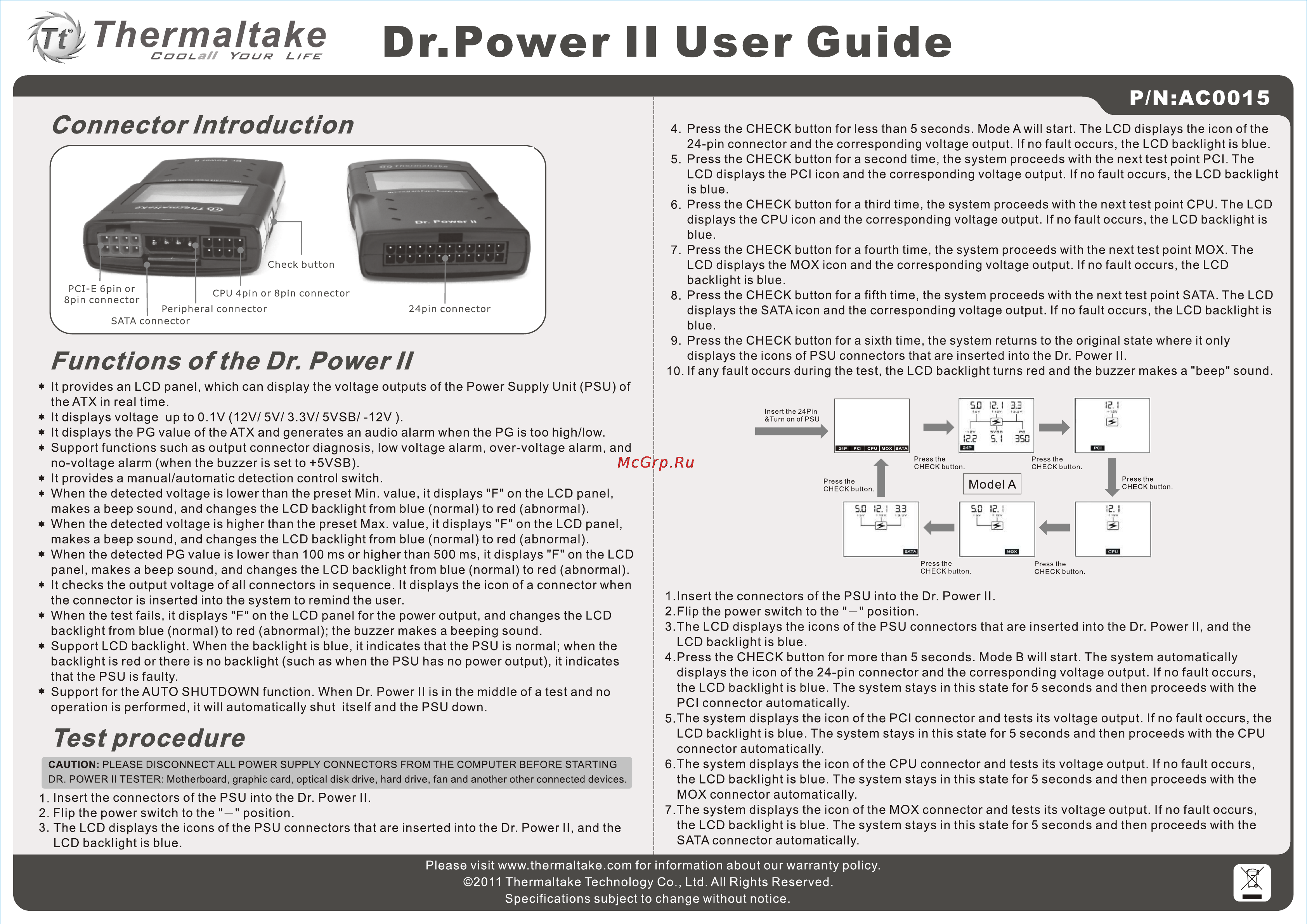
m Thermaltake CuuLaH YDUR rv LIFE Dr Power II User Guide P N AC0015 Connector Introduction PCI E 6pm or 8pin connector CPU 4pin or 8pin connector Peripheral connector SATA connector 24pin connector Functions of the Dr Power ii It provides an LCD panel which can display the voltage outputs of the Power Supply Unit PSU of the ATX in real time It displays voltage up to 0 1 V 12V 5V 3 3V 5VSB 12V It displays the PG value of the ATX and generates an audio alarm when the PG is too high low Support functions such as output connector diagnosis low voltage alarm over voltage alarm and no voltage alarm when the buzzer is set to 5VSB It provides a manual automatic detection control switch When the detected voltage is lowerthan the preset Min value it displays F on the LCD panel makes a beep sound and changes the LCD backlight from blue normal to red abnormal When the detected voltage is higher than the preset Max value it displays F on the LCD panel makes a beep sound and changes the LCD backlight from blue normal to red abnormal When the detected PG value is lower than 100 ms or higher than 500 ms it displays F on the LCD panel makes a beep sound and changes the LCD backlight from blue normal to red abnormal It checks the output voltage of all connectors in sequence It displays the icon of a connector when the connector is inserted into the system to remind the user When the test fails it displays F on the LCD panel for the power output and changes the LCD backlight from blue normal to red abnormal the buzzer makes a beeping sound Support LCD backlight When the backlight is blue it indicates that the PSU is normal when the backlight is red or there is no backlight such as when the PSU has no power output it indicates that the PSU is faulty Support for the AUTO SHUTDOWN function When Dr Power II is in the middle of a test and no operation is performed it will automatically shut itself and the PSU down Test procedure CAUTION PLEASE DISCONNECT ALL POWER SUPPLY CONNECTORS FROM THE COMPUTER BEFORE STARTING DR POWER II TESTER Motherboard graphic card optical disk drive hard drive fan and another other connected devices 1 Insert the connectors of the PSU into the Dr Power II 2 Flip the power switch to the position 3 The LCD displays the icons of the PSU connectors that are inserted into the Dr Power II and the LCD backlight is blue 4 Press the CHECK button for less than 5 seconds Mode A will start The LCD displays the icon of the 24 pin connector and the corresponding voltage output If no fault occurs the LCD backlight is blue 5 Press the CHECK button for a second time the system proceeds with the next test point PCI The LCD displays the PCI icon and the corresponding voltage output If no fault occurs the LCD backlight is blue 6 Press the CHECK button for a third time the system proceeds with the next test point CPU The LCD displays the CPU icon and the corresponding voltage output If no fault occurs the LCD backlight is blue 7 Press the CHECK button for a fourth time the system proceeds with the next test point MOX The LCD displays the MOX icon and the corresponding voltage output If no fault occurs the LCD backlight is blue 8 Press the CHECK button for a fifth time the system proceeds with the next test point SATA The LCD displays the SATA icon and the corresponding voltage output If no fault occurs the LCD backlight is blue 9 Press the CHECK button for a sixth time the system returns to the original state where it only displays the icons of PSU connectors that are inserted into the Dr Power II 10 If any fault occurs during the test the LCD backlight turns red and the buzzer makes a beep sound SD I5J 3 3 Insert the 24Pin Turn on of PSU IET 5 Í 350 Press the CHECK button Press the CHECK button Press the CHECK button Press the CHECK button I Model A I SE I 3 3 5 0 IP I Press the CHECK button Press the CHECK button 1 Insert the connectors of the PSU into the Dr Power II 2 Flip the power switch to the position 3 The LCD displays the icons of the PSU connectors that are inserted into the Dr Power II and the LCD backlight is blue 4 Press the CHECK button for more than 5 seconds Mode B will start The system automatically displays the icon of the 24 pin connector and the corresponding voltage output If no fault occurs the LCD backlight is blue The system stays in this state for 5 seconds and then proceeds with the PCI connector automatically 5 The system displays the icon of the PCI connector and tests its voltage output If no fault occurs the LCD backlight is blue The system stays in this state for 5 seconds and then proceeds with the CPU connector automatically 6 The system displays the icon of the CPU connector and tests its voltage output If no fault occurs the LCD backlight is blue The system stays in this state for 5 seconds and then proceeds with the MOX connector automatically 7 The system displays the icon of the MOX connector and tests its voltage output If no fault occurs the LCD backlight is blue The system stays in this state for 5 seconds and then proceeds with the SATA connector automatically Please visit www thermaltake com for information about our warranty policy 2011 Thermaltake Technology Co Ltd All Rights Reserved Specifications subject to change without notice