
Moxa IA262-I-T-LX Руководство по аппаратной части онлайн
— 1 — — 2 — — 3—
IA261/262
Quick Installation Guide
Second Edition, April 2009
1. Overview
The IA261/262 embedded computer comes with four RS-232/422/485
serial ports (for IA262, 2 of the ports are CANbus ports), dual 10/100
Mbps Ethernet ports, 8 digital input and 8 digital output channels, VGA
output, a CompactFlash socket for mass storage expansion, and USB
ports for keyboard/mouse connection or mass storage disk expansion. The
IA262’s dual CANbus ports are for connecting industrial automation
devices. These features make the IA261/262 series ideal for embedded
applications in harsh industrial environments, such as SCADA,
manufacturing automation, and other industrial applications.
2. Package Checklist
Before installing the IA261/262, verify that the package contains the
following items:
y 1 IA261/262 Embedded Computer
y Wall-Mounting Kit
y DIN-Rail Mounting Kit (attached to the product’s casing)
y Quick Installation Guide
y Document and Software CD
y Ethernet Cable: RJ45 to RJ45 cross-over cable, 100 cm
y CBL-4PINDB9F-100: 4-pin header to DB9 female console port cable,
100 cm
y Universal Power Adaptor
y Product Warranty Statement
NOTE: Please notify your sales representative if any of the above items
are missing or damaged.
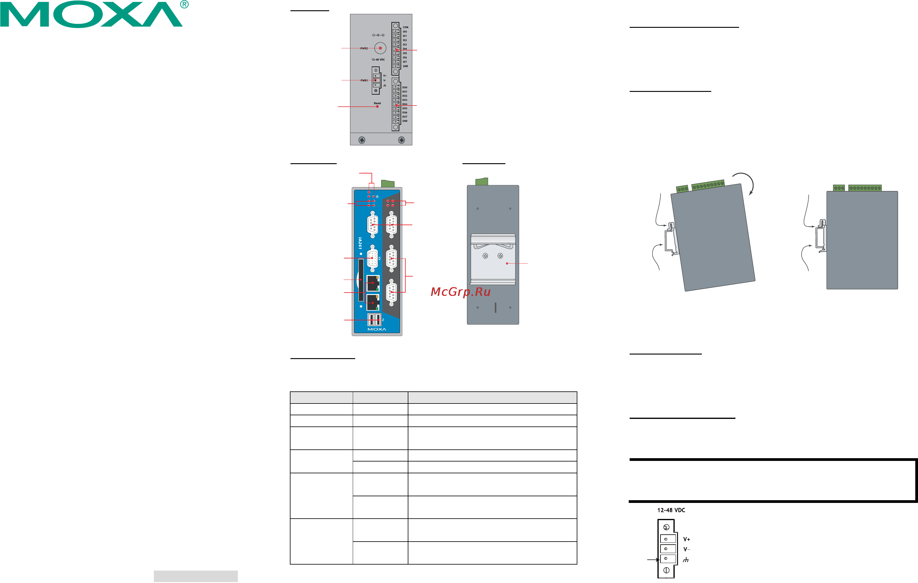
3. IA261/262 Panel Layout
The following figures show the panel layouts of the IA261 and IA262.
Top View
Reset Button
Power Input 1
Power Input 2
DI x 8
DO x 8
Front View
Rear View
LED Indicators
Serial, Tx/Rx
10/100 Mbps
Ethernet x 2
Powe r
Ready
P1
P2
RX TX
P
P
RX TX
LAN1
LAN2
CF
P4
RS-232/422/485
P3
RS-2
32/422/485
P1
RS-232/422/485
P2
RS-232/422/485
3
4
CompactFlash
Socket
Power, Ready,
Storage
LED Indicators
Serial, Tx/Rx
LED Indicators
CANBus, Tx/Rx
(IA262)
VGA Output
RS-232/422/485
Serial Port x 2
RS-232/422/485
Serial Port x 2
CANBus Port x 2
(IA262)
USB 2.0 Host x 2
DIN-Rail Kit
LED Indicators
The IA261/262 have 15 LED indicators on the front panel. Refer to the
following table for information about each LED.
LED Name LED Color LED Function
Power
Green Power is on
Ready
Green OS is ready and functioning normally
Storage
Green
Data is being written to or read from the
storage unit.
Orange 10 Mbps Ethernet connection
LAN 1/2
Green 100 Mbps Ethernet connection
Orange
Serial/CAN port is transmitting TX data
to the serial device.
P1-P4 (Tx)
Off Serial/CAN port is not transmitting TX
data to the serial device.
Orange Serial/CAN port is receiving RX data
from the serial device.
P1-P4 (Rx)
Off Serial/CAN port is not receiving RX data
to the serial device.
4. Installing the IA261/262
Wall or Cabinet Mounting
The IA261/262 comes with two metal brackets for attaching it to a wall
or the inside of a cabinet. Using two screws per bracket, first attach the
brackets to the rear of the IA261/262. Next, use two screws per bracket to
attach the IA261/262 to a wall or cabinet.
DIN-Rail Mounting
The aluminum DIN-Rail attachment plate is already attached to the
product casing. When attaching the plate to the IA261/262, make sure
that the stiff metal spring is at the top.
STEP 1: Insert the top of the
DIN-Rail into the slot just below the
stiff metal spring.
STEP 2: The DIN-Rail attachment
unit will snap into place as shown
below.
metal
spring
DIN-Rail
metal
spring
DIN-Rail
To remove the IA261/262 from the DIN-Rail, simply reverse Steps 1 and
2 above.
5. Connector Description
Power Connector
Connect the 12 to 48 VDC LPS or Class 2 power line to the IA261/262’s
terminal block or power jack. If the power is properly supplied, the
Power LED will light up. The OS is ready when the Ready LED glows a
solid green.
Grounding the IA261/262
Grounding and wire routing help limit the effects of noise due to
electromagnetic interference (EMI). Run the ground connection from the
ground screw to the grounding surface prior to connecting the power.
ATTENTION
This product is intended to be mounted to a well-grounded mounting
surface, such as a metal panel.
SG
SG: The Shielded Ground (sometimes called Protected
Ground) contact is the bottom contact of the 3-pin
power terminal block connector when viewed from
the angle shown here. Connect the SG wire to an
appropriate grounded metal surface.
P/N: 1802002600031
Содержание
Похожие устройства
- Moxa IA262-I-T-LX Технические характеристики
- Moxa IA262-I-T-LX Руководство по быстрой установке
- Moxa IA262-I-T-LX Руководство по работе с утилитой Moxa Device Manager
- Moxa IA3341-LX Инструкция по эксплуатации
- Moxa IA3341-LX Технические характеристики
- Moxa IA3341-LX Руководство по аппаратной части
- Moxa IA3341-LX Руководство по быстрой установке
- Moxa IA3341-LX Руководство по работе с утилитой Moxa Device Manager
- Moxa V2406A-C2 Инструкция по эксплуатации
- Moxa V2406A-C2 Технические характеристики
- Moxa V2406A-C2 Руководство по аппаратной части
- Moxa V2406A-C2 Руководство по быстрой установке
- Moxa V2406A-C2-T Инструкция по эксплуатации
- Moxa V2406A-C2-T Руководство по аппаратной части
- Moxa V2406A-C2-T Технические характеристики
- Moxa V2406A-C2-T Руководство по быстрой установке
- Moxa V2406A-C2-W7E Инструкция по эксплуатации
- Moxa V2406A-C2-W7E Руководство по аппаратной части
- Moxa V2406A-C2-W7E Технические характеристики
- Moxa V2406A-C2-W7E Руководство по быстрой установке