
Moxa OnCell 5004-HSPA Руководство по аппаратной части онлайн
– 1 – – 2 – – 3 – - 4 -
P/N: 1802050040013
OnCell 5004/5104 Series
Quick Installation Guide
Fourth Edition, April 2014
Overview
The OnCell 5004/5104 series are high-performance industrial grade
cellular routers that allow up to 4 Ethernet-based devices to
simultaneously use a single cellular data account for primary or
backup network connectivity to remote sites and devices. Both
products provide the functionality of a cellular router, firewall, and
switch in one single device. The difference between the OnCell 5004
and the 5104 series is that the OnCell 5104 comes with a built-in
relay output that can be configured to indicate the priority of events
to notify and warn engineers in the field, and the two digital inputs
allow you to connect basic I/O devices, such as sensors, to the
cellular router. In addition, the OnCell 5104 has an IA design and can
be attached to a DIN-rail, whereas the OnCell 5004 can be placed on
a desktop or be wall-mounted. Both products use 12 to 48 VDC
power inputs with a screw-on connector for greater reliability, and
the Ethernet port comes with 1.5 KV magnetic isolation protection to
keep your system safe from unexpected electrical discharges.
Package Checklist
Before Installing the OnCell 5004/5104 series Cellular Router, verify
that the package contains the following items:
Standard Accessories
• Rubber SMA antenna
• Rubber stand (OnCell 5004 series only)
• Wallmount Kit (OnCell 5004 series only)
• Din-Rail Kit (OnCell 5104 series only)
• Terminal block (screw type)
• Document and Software CD
• Product warranty statement
• Quick Installation Guide
Note: Please notify your sales representative if any of the above
items are missing or damaged.
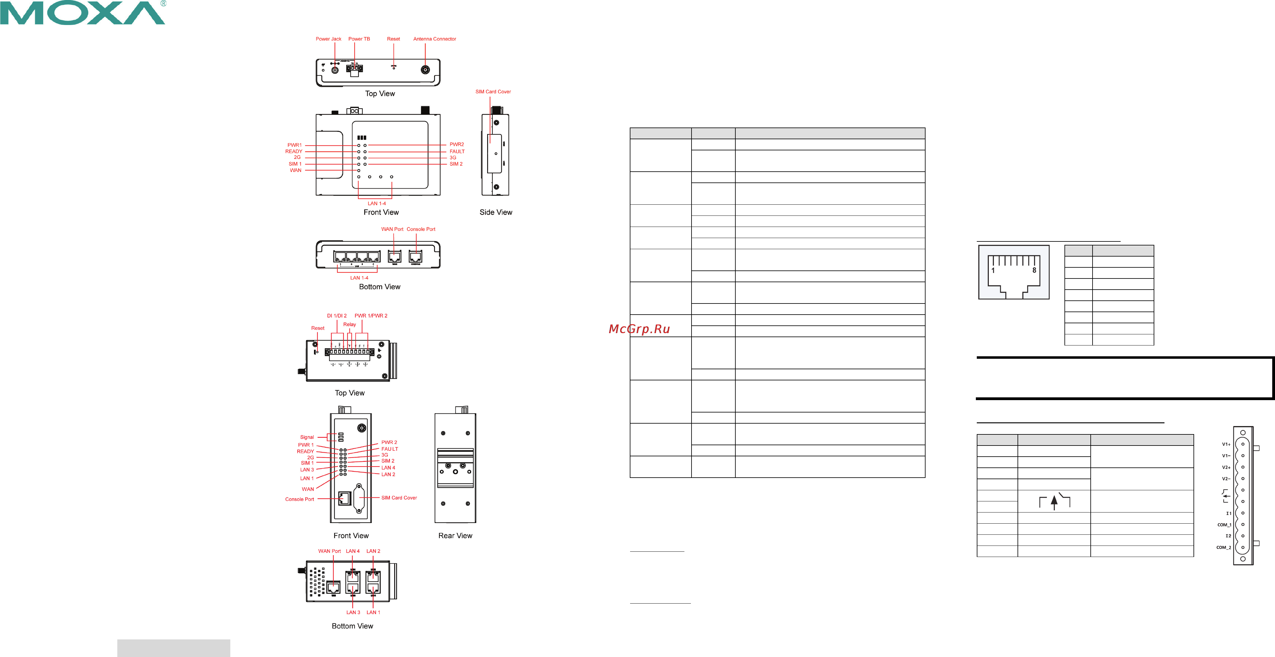
Hardware Introduction
OnCell 5004 series
OnCell 5104 series
Reset Button
Press the Reset Button continuously for 5 sec to load factory default
settings. Use a pointed object, such as a straightened paper clip or
toothpick, to press the reset button. This will cause the Ready LED to
blink on and off. The factory default settings will be loaded once the
Ready LED stops blinking (default LAN IP: 192.168.127.254).
LED Indicators
The following table explains the LED indicators on the front panel of
the OnCell 5004/5104 series:
Type
Color
Meaning
PWR 1
Green
Activation of DC Power
Off
Power is off, or power error condition
exists.
PWR 2
Green
Activation of DC Power
Off
Power is off, or power error condition
exists.
2G
Amber
GPRS/EDGE is connected
Off
GPRS/EDGE is disconnected
3G
Amber
UMTS/HSPA is connected
Off
UMTS/HSPA is disconnected
SIM 1
Amber
Steady on: SIM 1 is activated
Blinking: SIM 1 not inserted
Off
SIM 1 is inactivated
SIM 2
Amber
Steady on: SIM 2 is activated
Blinking: SIM 2 not inserted
Off
SIM 2 is inactivated
WAN
Amber
WAN port is connected
off
WAN port is not connected
Ready
Green
Steady on: Software Ready.
Blinking slowly (1 sec): The OnCell has
been located by the OnCell Search Utility.
off
Power is off, or is booting up.
Fault
Red
Steady on: Booting up, or IP fault.
Blinking slowly (1 sec): Cannot get an IP
address from the DHCP server
off
Power is off, or there is no error condition.
LAN 1-4
Green
Steady on: Software Ready.
Blinking slowly (1 sec): Data transmission
off
Power is off, or is booting up.
Signal
(3 LEDs)
Green
Signal Level (at least 2 LEDs must
illuminated for data Transmission)
Connecting the I/O Port
The OnCell 5104/5104 series has six terminals on the terminal block
for the I/O ports, with 4 terminals used for input, and 2 terminals
used for output.
Digital Input—The power input level determines the digital input’s
ON/OFF state:
On: +13 to +30 V for state “1”
Off: -30 to +3 V for state “0”
Digital Output—1 relay output with current carrying capacity of 1 A
@ 24 VDC.
Hardware Installation Procedure
STEP 1: Open the SIM cover, and insert the SIM card into the SIM
card slot.
STEP 2: Connect the 12-48 VDC power adaptor to the OnCell
5004/5104 series and then plug the power adaptor into a DC outlet.
STEP 3: To configure the OnCell, use an Ethernet cable to connect
the OnCell’s LAN port directly to your computer’s Ethernet interface.
STEP 4: Connect the OnCell 5004/5104 series’ Ethernet port to an
Ethernet enabled device.
Software Installation Information
The Document & Software CD contains the User’s Manual, and the
OnCell Search Utility. Insert the CD and follow the on-screen
instructions. Please refer to the User’s Manual for additional details
on using the OnCell Search Utility.
Pin Assignments and Cable Wiring
Ethernet Port Pin Assignment
Pin
RS-232
1
TxD+
2
TxD-
3
RxD+
4
---
5
---
6
RxD-
7
---
8
---
NOTE
Please read Chapter 2: Getting Started in the OnCell 5000
Series
User’s Manual
for more details about installation and
configuration.
Power Input and Relay Output Pinouts
PIN
Name
Function
1
V1+
DC Power Input 1
2
V1-
3
V2+
DC Power Input 2
4
V2-
5
Relay Output
6
7
I1
Digital Input
8
COM_1
Digital Input GND
9
I2
Digital Input
10
COM_2
Digital Input GND
Содержание
- Connecting the i o port 1
- Fourth edition april 2014 1
- Hardware installation procedure 1
- Hardware introduction 1
- Led indicators 1
- Oncell 5004 5104 series quick installation guide 1
- Oncell 5004 series 1
- Oncell 5104 series oncell 5104 series 1
- Overview 1
- Package checklist 1
- Pin assignments and cable wiring 1
- Reset button 1
- Software installation information 1
- Specifications 2
Похожие устройства
- Orion DRL-12LED 36W Руководство по эксплуатации
- Moxa OnCell 5104-HSPA-T Инструкция по эксплуатации
- Moxa OnCell 5104-HSPA-T Руководство по программной части
- Moxa OnCell 5104-HSPA-T Технические характеристики
- Moxa OnCell 5104-HSPA-T Руководство по аппаратной части
- Orion FOG LIGHT 5W-40мм Руководство по эксплуатации
- Moxa OnCell 5104-HSPA Инструкция по эксплуатации
- Moxa OnCell 5104-HSPA Руководство по программной части
- Moxa OnCell 5104-HSPA Технические характеристики
- Moxa OnCell 5104-HSPA Руководство по аппаратной части
- Orion FOG LIGHT 10W-64мм Руководство по эксплуатации
- Moxa WDR-3124A-EU Инструкция по эксплуатации
- Moxa WDR-3124A-EU Руководство по подключению
- Moxa WDR-3124A-EU Технические характеристики
- Moxa WDR-3124A-EU-T Инструкция по эксплуатации
- Moxa WDR-3124A-EU-T Руководство по подключению
- Moxa WDR-3124A-EU-T Технические характеристики
- Orion DRL-17,5 CM Руководство по эксплуатации
- Orion DRL-SF-72 Руководство по эксплуатации
- Orion DRL-FG-10 Руководство по эксплуатации