![Sony KV-25FX30K — ошибки и диагностика в системе FE-2: руководство пользователя [5/50]](/img/pdf.png)
Sony KV-25FX30K — ошибки и диагностика в системе FE-2: руководство пользователя [5/50]
![Sony KV-25FX30K [5/50] Fe 2 self diagnostic software](/views2/1307614/page5/bg5.png)
5
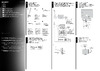
FE-2 SELF DIAGNOSTIC SOFTWARE
The identification of errors within the FE-2 chassis is triggered in one of two ways :- 1: Busy or 2: Device failure to respond to IIC. In the event
of one of these situations arising the software will first try to release the bus if busy (Failure to do so will report with a continuous flashing
LED) and then communicate with each device in turn to establish if a device is faulty. If a device is found to be faulty the relevant device number
will be displayed through the LED (Series of flashes which must be counted) See table 1., non fatal errors are reported using this method.
Each time the software detects an error it is stored within the NVM. See Table 2.
Flash Timing Example : e.g. error number 3
StBy LED
ON ON ON
OFF
OFF
Table 1
How to enter into Table 2
1. Turn on the main power switch of the TV set and enter into
the
‘Stanby Mode’.
2. Press the following sequence of buttons on the Remote
Commander.
i+
5
-
(ON SCREEN (DIGIT 5) (VOLUME -) (TV)
DISPLAY)
3. The following table will be displayed indicating the error
count.
Table 2
Note: To clear the error count data press ‘80’ on the Remote
commander.
UNEMRORRE
20E
30E
40E
50E
60E
70E
80E
90E
01E
11E
EMITGNIKROW
SRUOH
SETUNIM
PCO
A/NPVO
CNYSV
RKI
CII
MVN
ELGNUJ
RENUT
PDNUOS
V8
)552,0(
)552,0(
)552,0(
)552,0(
)552,0(
)552,0(
)552,0(
)552,0(
)552,0(
)552,0(
0
0
0
0
0
0
0
0
0
0
2
11
egasseMrorrE
DEL
edoC
rorreoN00
devreseR10
)noitcetorPtnerruCrevO(PCO20
desUtoN30
cnySlacitreVoN40
norewoptarorrERKI50
norewoptawolsenilatadro/dnakcolcsubCII60
norewoptaegdelwonkcasubCIIonMVN70
desUtoN80
norewoptaegdelwonkcaonrenuT90
rorrErossecorPdnuoS01
rorrestlov8rellortnocelgnuJ11
Содержание
- Kv 25fx30k p.1
- Kv 29fx30k p.1
- Service manual fe p.1
- Kv 25fx30e p.1
- Chassis p.1
- Kv 25fx30b p.1
- Kv 29fx30e p.1
- Kv 29fx30b p.1
- Table of contents p.2
- S video socket p.4
- Pin connector p.4
- Rear connection panel front connection panel p.4
- Fe 2 self diagnostic software p.5
- Switching on the tv and automatically tuning p.6
- Section p.6
- Menu guide p.7
- Introducing and using the menu system p.7
- Level 1 level 2 level 3 function p.8
- Level 1 level 2 level 3 function p.9
- Teletext p.10
- If you have connected a decoder to a vcr which supports smartlink feature p.10
- Fastext p.10
- Connecting optional equipment p.10
- Connecting a vcr that supports smartlink p.10
- Connecting a vcr p.10
- Specifications p.11
- Troubleshooting p.11
- Section p.12
- Disassembly p.12
- When one side of the rubber cap is separated from the anode button the anode cap can be removed by turning up the rubber cap and pulling it up in the direction of the arrow c p.14
- Turn up one side of the rubber cap in the direction indicated by the arrow a 1 2 using a thumb pull up the rubber cap firmly in the direction indicated by the arrow b p.14
- Set up adjustments p.16
- Section p.16
- 1 beam landing p.16
- 2 convergence p.17
- Tilt direction p.18
- 4 screen g2 white balance p.19
- 3 focus adjustment p.19
- Section 4 p.20
- Circuit adjustments p.20
- 1 electrical adjustments p.20
- Enter into the geometry service menu 2 select and adjust each item in order to obtain the optimum image p.21
- Tuner agc adjustment p.21
- Print side of a board p.21
- Note there should be no need to adjust the agc as this is pre adjusted during manufacture of the frontend if the agc does need adjustment then follow steps 1 to 4 below p.21
- Deflection system adjustment p.21
- B out waveform p.21
- Sub colour adjustment p.21
- Same level p.21
- Receive a signal of 62dbuv 75 ohm terminated via the tuner antenna socket 2 connect a voltmeter to pin1 of tu101 print side of a board or to the agc pin of cn001 mount side of a board 3 confirm that the agc voltage is 3 volts 0 volts 4 if adjustment is required then re adjust the agc variable resistor located at the top rear of the frontend to obtain a voltage of 3 v 0 v p.21
- Receive a pal colour bar signal 2 connect an oscilloscope to pin 5 of cn003 a board 3 enter into the service service menu 4 adjust the sub colour data so that the cyan magenta and blue colour bars are of equal levels as indicated below p.21
- 1 t n e m ts ujd a r u olo c b u s p.22
- 1 0 5 le v el e r u tci p p.22
- 0 n oitid n o c g nip pih s p.22
- 0 m u m ix a m e r u tci p p.22
- Test mode 2 is available by pressing the test button twice osd tt appears the functions described below are available by selecting the two numbers to release the test mode 2 press 00 10 20 twice or switch the tv set into stand by mode in tt menu mode it is possible to remove the menu from the screen by pressing the speaker off button once pressing the speaker off button a second time will cause the menu to reappear the function is kept even when the menu is not displayed on screen p.22
- 0 m u m ini m e r u tci p p.22
- Test mode 1 is available by pressing the test button once osd t appears the functions described below are available by selecting the indicated keys the t is released automatically after each command is executed p.22
- 0 ff o e d o m t t p.22
- 3 test mode 2 p.22
- 0 e d o m g nie g a p.22
- 2 u n oit a nits e d p.22
- 0 5 6 o t e m ulo v e n o h p d a e h r e k a e p s t e s p.22
- 2 test mode 1 p.22
- 0 5 3 o t e m ulo v e n o h p d a e h r e k a e p s t e s p.22
- 2 r k e d a n oit a nits e d p.22
- 0 0 8 o t e m ulo v e n o h p d a e h r e k a e p s t e s p.22
- 2 l b n oit a nits e d p.22
- 0 0 5 o t e m ulo v e n o h p d a e h r e k a e p s t e s p.22
- 1 ts e t lio c n oit a t o r p.22
- 1 t n e m ts ujd a s s e n t h gir b b u s p.22
- 1 t n e m ts ujd a n oitis o p h tx e t p.22
- 1 t n e m ts ujd a e r u tcip b u s p.22
- 1 elb a si d elb a n e e d o m y r o tc a f p.22
- Dy assy p.23
- 1 block diagrams 1 p.23
- 3 schematic diagrams and printed wiring boards p.24
- The components identified by shading and marked are critical for safety replace only with the part numbers specified in the parts list p.24
- S1 board p.24
- Reference information p.24
- Neck assy p.24
- Les composants identifiés par une trame et par une marque sont d une importance critique pour la sécurité ne les remplacer que par des pièces de numéro spécifié specified p.24
- Cvm board p.24
- A board p.24
- R g b out p.25
- Ic voltage table p.25
- C boardwaveforms p.25
- C board waveforms p.25
- Velocity modulation p.26
- Difference table p.26
- Printed wiring board p.28
- Difference table p.28
- A b c d e f g h i j k l m p.28
- Semiconductor voltage table ic voltage table p.28
- Semiconductor location table p.28
- Kv 25 29fx30 p.29
- Power supply deflection audio amplifier page 2 2 p.30
- A board waveforms p.30
- 4 semiconductors p.31
- A board ic604 ba41w12st v5 p.33
- A board ic601 mcz3001d p.33
- A board ic401 ic531 lm393dt p.33
- A board ic1201 tda7497 p.33
- 5 ic block diagrams p.33
- Section 6 exploded views p.34
- 1 chassis p.34
- 2 picture tube p.35
- Section 7 electrical parts list p.36
- A f4 a p.40
- C d vm p.46
- The trace interface connects to the pc s serial port it provides connection to the tv s i 2 c bus and can be provided with an infrared transmitter optional p.50
- The interface is powered by a standard 9 v pp3 battery for portable use and can also be powered by an external 9v 25ma dc power supply p.50
- Sony uk service promotions dept p.50
- Sony corporation p.50
- Pc requirements ibm compatible pc with operating system windows95 windows98 or windowsnt p.50
- Partnumbers trace starter kit trace interface software 9 948 320 70 trace software for users of the i 2 c link interface 9 948 340 80 trace ir add on ir interface remote commander software 9 948 320 80 p.50
- English 01ep7140 1 printed in u k 2001 p.50
- A new tv repair assistance tool that combines ease of use and powerful pc software tools to allow you to save valuable time during many tv repairs p.50
- 927 405 01 p.50
Похожие устройства
-
 Sony kdl-55wd655Инструкция по установке
 -
 Sony KDL-32W503AИнструкция к устройству
 -
 Sony KD-49XF90xxИнструкция по монтажу
 -
 Sony kdl-32wd603Инструкция по работе
 -
Sony kdl-40rd453Инструкция к устройству
-
Sony kdl-40wd653Инструкция по применению
-
Sony kdl-48wd653Эксплуатационная инструкция
-
 Sony KLV-S19A10EИнструкция по эксплуатации
 -
Sony KLV-S23A10EИнструкция по эксплуатации
-
Sony KLV-S26A10EИнструкция по эксплуатации
-
Sony KLV-S32A10EИнструкция по эксплуатации
-
Sony KLV-S40A10EИнструкция по эксплуатации
Узнайте, как диагностировать ошибки в системе FE-2 с помощью самодиагностического программного обеспечения. Пошаговые инструкции и советы по устранению неполадок.