![Sony KV-25FX30K — настройка телевизора: сортировка программ и метки каналов [8/50]](/img/pdf.png)
Sony KV-25FX30K — настройка телевизора: сортировка программ и метки каналов [8/50]
![Sony KV-29FX30K [8/50] Level 1 level 2 level 3 function](/views2/1307614/page8/bg8.png)
8
12
Menu System
continued...
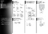
PROGRAMME SORTING
The “Programme Sorting” option in the “Set
Up” menu allows you to change the order in
which the channels (TV Broadcast) appear on
the screen.
To do that: after selecting the option, press
and then proceed in the same way as in step 7 b)
of the section “Switching On the TV and
Automatically Tuning”.
PROGRAMME LABELS
The “Programme Labels” option in the “Set
Up” menu allows you to name a channel using
up to five characters (letters or numbers).
To do that:
1 After selecting the option, press , then
press or to select the programme
number with the channel you wish to name.
2 Press . With the first element of the Label
column highlighted, press or to select
a letter or number (select “-“ for a blank), then
press to confirm this character. Select the
other four characters in the same way. Finally
press OK to store.
AV PRESET
The “AV Preset” option in the “Set Up” menu
allows you to designate a name to the external
equipment you have connected to the sockets of
this TV.
To do that:
1 After selecting the option, press , then
press or to select the input source you
wish to name (AV1 and AV2 are for the rear
Scarts and AV3 for front connectors). Then
press .
2 In the label column automatically appears a
label:
a) If you want to use one of the 6 predefined
label (CABLE, GAME, CAM, DVD,
VIDEO or SAT), press or to select
the desired label and finally press OK to
store.
b) If you want to set a different label, select
Edit and press . Then with the first
element highlighted, press or to
select a letter, number or “-“ for a blank,
then press to confirm this character.
Select the other four characters in the same
way and finally press OK to store.
Level 1 Level 2 Level 3 / Function
Picture Adjustment
Mode: Personal
Contrast
Brightness
Colour
Sharpness
Hue
Reset
OK
Set Up
Language/Country
Auto Tuning
Programme Sorting
Progamme Labels
AV Preset
Manual Programme Preset
Detail Set Up
OK
Set Up
Language/Country
Auto Tuning
Programme Sorting
Progamme Labels
AV Preset
Manual Programme Preset
Detail Set Up
OK
11
GB
Menu System
SLEEP TIMER
The “Sleep Timer” option in the “Timer” menu
allows you to select a time period for the TV to
switch itself automatically into the standby
mode.
To do that: after selecting the option press ,
then press or to set the time period delay
(max. of 4 hours) and finally press OK to store.
• While watching the TV, you can press the
button on the remote control to display the
time remaining.
• One minute before the TV switches itself into
standby mode, the time remaining is displayed on
the TV screen automatically.
LANGUAGE / COUNTRY
The “Language/Country” option in the “Set
Up” menu allows you to select the language
that the menus are displayed in. It also allows
you to select the country in which you wish to
operate the TV set.
To do that: after selecting the option, press
and then proceed in the same way as in the
steps 2 and 3 of the section “Switching On the
TV and Automatically Tuning”.
AUTO TUNING
The “Auto Tuning” option in the “Set Up”
menu allows you to automatically search for
and store all available TV channels.
To do that: after selecting the option, press
and then proceed in the same way as in TV
steps 5 and 6 of the section “Switching On the
TV and Automatically Tuning”.
Level 1 Level 2 Level 3 / Function
Picture Adjustment
Mode: Personal
Contrast
Brightness
Colour
Sharpness
Hue
Reset
OK
Timer
Sleep Timer: Off
OK
Timer
Sleep Timer: Off
OK
continued...
Picture Adjustment
Mode: Personal
Contrast
Brightness
Colour
Sharpness
Hue
Reset
OK
Set Up
Language/Country
Auto Tuning
Programme Sorting
Progamme Labels
AV Preset
Manual Programme Preset
Detail Set Up
OK
Set Up
Language/Country
Auto Tuning
Programme Sorting
Progamme Labels
AV Preset
Manual Programme Preset
Detail Set Up
OK
Содержание
- Kv 25fx30k p.1
- Kv 29fx30k p.1
- Service manual fe p.1
- Kv 25fx30e p.1
- Chassis p.1
- Kv 25fx30b p.1
- Kv 29fx30e p.1
- Kv 29fx30b p.1
- Table of contents p.2
- S video socket p.4
- Pin connector p.4
- Rear connection panel front connection panel p.4
- Fe 2 self diagnostic software p.5
- Switching on the tv and automatically tuning p.6
- Section p.6
- Menu guide p.7
- Introducing and using the menu system p.7
- Level 1 level 2 level 3 function p.8
- Level 1 level 2 level 3 function p.9
- Teletext p.10
- If you have connected a decoder to a vcr which supports smartlink feature p.10
- Fastext p.10
- Connecting optional equipment p.10
- Connecting a vcr that supports smartlink p.10
- Connecting a vcr p.10
- Specifications p.11
- Troubleshooting p.11
- Section p.12
- Disassembly p.12
- When one side of the rubber cap is separated from the anode button the anode cap can be removed by turning up the rubber cap and pulling it up in the direction of the arrow c p.14
- Turn up one side of the rubber cap in the direction indicated by the arrow a 1 2 using a thumb pull up the rubber cap firmly in the direction indicated by the arrow b p.14
- Set up adjustments p.16
- Section p.16
- 1 beam landing p.16
- 2 convergence p.17
- Tilt direction p.18
- 4 screen g2 white balance p.19
- 3 focus adjustment p.19
- Section 4 p.20
- Circuit adjustments p.20
- 1 electrical adjustments p.20
- Enter into the geometry service menu 2 select and adjust each item in order to obtain the optimum image p.21
- Tuner agc adjustment p.21
- Print side of a board p.21
- Note there should be no need to adjust the agc as this is pre adjusted during manufacture of the frontend if the agc does need adjustment then follow steps 1 to 4 below p.21
- Deflection system adjustment p.21
- B out waveform p.21
- Sub colour adjustment p.21
- Same level p.21
- Receive a signal of 62dbuv 75 ohm terminated via the tuner antenna socket 2 connect a voltmeter to pin1 of tu101 print side of a board or to the agc pin of cn001 mount side of a board 3 confirm that the agc voltage is 3 volts 0 volts 4 if adjustment is required then re adjust the agc variable resistor located at the top rear of the frontend to obtain a voltage of 3 v 0 v p.21
- Receive a pal colour bar signal 2 connect an oscilloscope to pin 5 of cn003 a board 3 enter into the service service menu 4 adjust the sub colour data so that the cyan magenta and blue colour bars are of equal levels as indicated below p.21
- 1 t n e m ts ujd a r u olo c b u s p.22
- 1 0 5 le v el e r u tci p p.22
- 0 n oitid n o c g nip pih s p.22
- 0 m u m ix a m e r u tci p p.22
- Test mode 2 is available by pressing the test button twice osd tt appears the functions described below are available by selecting the two numbers to release the test mode 2 press 00 10 20 twice or switch the tv set into stand by mode in tt menu mode it is possible to remove the menu from the screen by pressing the speaker off button once pressing the speaker off button a second time will cause the menu to reappear the function is kept even when the menu is not displayed on screen p.22
- 0 m u m ini m e r u tci p p.22
- Test mode 1 is available by pressing the test button once osd t appears the functions described below are available by selecting the indicated keys the t is released automatically after each command is executed p.22
- 0 ff o e d o m t t p.22
- 3 test mode 2 p.22
- 0 e d o m g nie g a p.22
- 2 u n oit a nits e d p.22
- 0 5 6 o t e m ulo v e n o h p d a e h r e k a e p s t e s p.22
- 2 test mode 1 p.22
- 0 5 3 o t e m ulo v e n o h p d a e h r e k a e p s t e s p.22
- 2 r k e d a n oit a nits e d p.22
- 0 0 8 o t e m ulo v e n o h p d a e h r e k a e p s t e s p.22
- 2 l b n oit a nits e d p.22
- 0 0 5 o t e m ulo v e n o h p d a e h r e k a e p s t e s p.22
- 1 ts e t lio c n oit a t o r p.22
- 1 t n e m ts ujd a s s e n t h gir b b u s p.22
- 1 t n e m ts ujd a n oitis o p h tx e t p.22
- 1 t n e m ts ujd a e r u tcip b u s p.22
- 1 elb a si d elb a n e e d o m y r o tc a f p.22
- Dy assy p.23
- 1 block diagrams 1 p.23
- 3 schematic diagrams and printed wiring boards p.24
- The components identified by shading and marked are critical for safety replace only with the part numbers specified in the parts list p.24
- S1 board p.24
- Reference information p.24
- Neck assy p.24
- Les composants identifiés par une trame et par une marque sont d une importance critique pour la sécurité ne les remplacer que par des pièces de numéro spécifié specified p.24
- Cvm board p.24
- A board p.24
- R g b out p.25
- Ic voltage table p.25
- C boardwaveforms p.25
- C board waveforms p.25
- Velocity modulation p.26
- Difference table p.26
- Printed wiring board p.28
- Difference table p.28
- A b c d e f g h i j k l m p.28
- Semiconductor voltage table ic voltage table p.28
- Semiconductor location table p.28
- Kv 25 29fx30 p.29
- Power supply deflection audio amplifier page 2 2 p.30
- A board waveforms p.30
- 4 semiconductors p.31
- A board ic604 ba41w12st v5 p.33
- A board ic601 mcz3001d p.33
- A board ic401 ic531 lm393dt p.33
- A board ic1201 tda7497 p.33
- 5 ic block diagrams p.33
- Section 6 exploded views p.34
- 1 chassis p.34
- 2 picture tube p.35
- Section 7 electrical parts list p.36
- A f4 a p.40
- C d vm p.46
- The trace interface connects to the pc s serial port it provides connection to the tv s i 2 c bus and can be provided with an infrared transmitter optional p.50
- The interface is powered by a standard 9 v pp3 battery for portable use and can also be powered by an external 9v 25ma dc power supply p.50
- Sony uk service promotions dept p.50
- Sony corporation p.50
- Pc requirements ibm compatible pc with operating system windows95 windows98 or windowsnt p.50
- Partnumbers trace starter kit trace interface software 9 948 320 70 trace software for users of the i 2 c link interface 9 948 340 80 trace ir add on ir interface remote commander software 9 948 320 80 p.50
- English 01ep7140 1 printed in u k 2001 p.50
- A new tv repair assistance tool that combines ease of use and powerful pc software tools to allow you to save valuable time during many tv repairs p.50
- 927 405 01 p.50
Похожие устройства
-
 Sony kdl-55wd655Инструкция по установке
 -
 Sony KDL-32W503AИнструкция к устройству
 -
 Sony KD-49XF90xxИнструкция по монтажу
 -
 Sony kdl-32wd603Инструкция по работе
 -
Sony kdl-40rd453Инструкция к устройству
-
Sony kdl-40wd653Инструкция по применению
-
Sony kdl-48wd653Эксплуатационная инструкция
-
 Sony KLV-S19A10EИнструкция по эксплуатации
 -
Sony KLV-S23A10EИнструкция по эксплуатации
-
Sony KLV-S26A10EИнструкция по эксплуатации
-
Sony KLV-S32A10EИнструкция по эксплуатации
-
Sony KLV-S40A10EИнструкция по эксплуатации
Узнайте, как настроить порядок каналов и задать им имена на вашем телевизоре. Пошаговые инструкции по сортировке программ и настройке внешних устройств.