
Aspen pumps Compressor Sensor Рump Инструкция по эксплуатации онлайн
Aspen Compressor Sensor Pump
Install your pump outside.
Description:
The pump is designed to be installed in the ceiling void and to lift condensated water
where a gravity drain is too obtrusive. It can also be fitted within the external
condenser unit (as long the pump and it's plug/socket are sheltered and fully
protected from water ingress), which makes it ideal for applications where complete
silence is important. The pump is triggered by a sensor, which is designed to be
mounted onto the compressor in an external condenser unit. When the air
conditioning system starts up, the compressor produces a localised electro-magnetic
field, triggering the sensor, which in turn activates the peristaltic pump.
The pump runs constantly while the compressor is operational. When the compressor
switches off, a 3 minute over-run timer ensures that the condensate tray is emptied
before the pump switches off. Rollers in the pump act as check valves to stop the
condensate draining back into the condensate tray.
Installation Notes:
Decide where the pump will be located and connect it to the appropriate drip tray
(using 6mm I/D vinyl tube), then connect to a 240V mains power supply. Install a 1A
in-line fuse in the Live line between the pump and the power source.
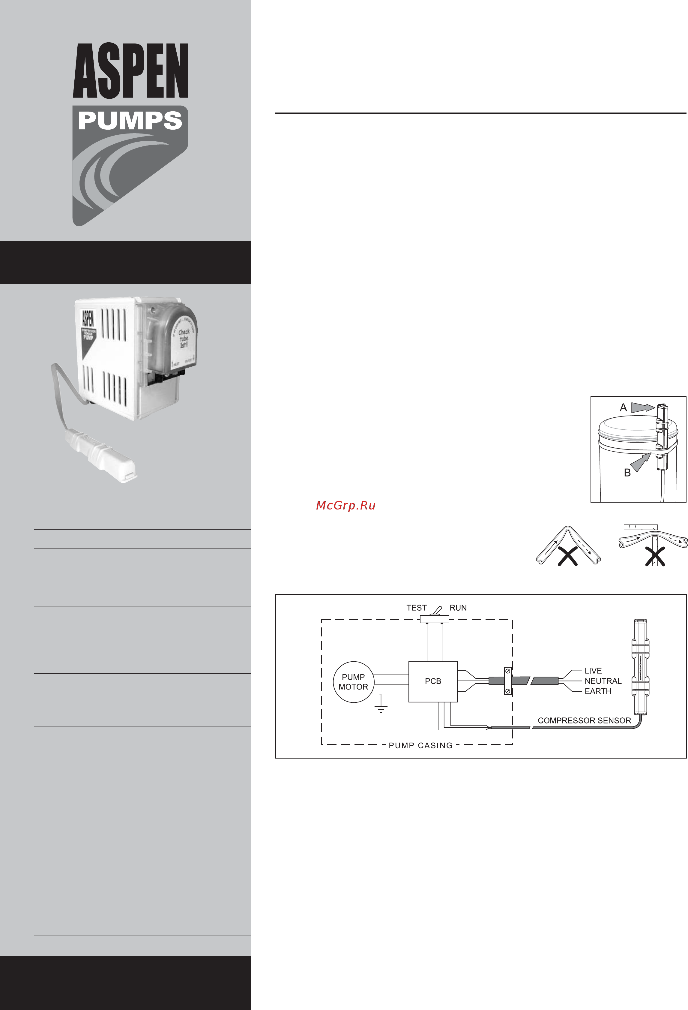
Position the sensor vertically against the compressor, so it
protrudes above the top of the compressor like an aerial (A).
This is important as it is where the electromagnetic field is
strongest. Use the cable tie supplied to fix the sensor securely
to the compressor (B). A 10m sensor cable is supplied, which
can be extended if required.
The pump is designed to fit level on its base and MUST have
adequate ventilation space around it at all times.
Ensure that there are no kinks or trapped sections in the
piping, which must have a 6mm I/D and 9mm O/D. Fix
the pipes with cable ties to the pump inlet & outlet.
A variable connector is provided to allow easy fixing
between the condensate outlet tray and the vinyl tube.
Service Guide:
1 Inspect the pump head regularly and change the pump head tube every
12 months or more often if required.
2 To remove the pump head, make sure the roller assembly is vertical. Remove
screws and fit the replacement pipe. The addition of a smear of silicon grease will
ease refitting the lid and reduce potential friction noise.
3 The test switch should always be returned to the “RUN” position after testing.
4 Replacement pump head tubes and other accessories can be obtained from the
manufacturers. Please quote the serial number (to be found on the pump) when
ordering spare parts.
DO NOT RUN CONTINUOUSLY
For further help contact Aspen Pumps:
Aspen Pumps Apex Way Hailsham East Sussex BN27 3WA www.aspenpumps.com
Tel: +44 (0)1323 848842 Fax: +44 (0)1323 848846 sales@aspenpumps.com
DATA SHEET
DESIGNED BY ENGINEERS
FOR ENGINEERS
Pt No. 2478
Technical Specification:
•
Mains cable: 2m
•
Sensor cable: 10m
•
Self-priming
•
5 metre suction lift
•
12 metre discharge head
•
Pumps water/fibrously
contaminated water and air
•
Water pumping capacity 6.25 litres per
hour @ 12m discharge
•
Pump has a selector switch for manual
flushing
•
Pump has a 3 minute over-run timer
•
Temperature limits on pump head tube:
0 to +100°C
•
Pump rating 0.2A, 240V AC
Dimensions:
Height: 142mm Width: 160mm
Depth: 83mm Weight: 1.7kg
Electrical Connections:
Brown: Live
Blue: Neutral
Green/yellow: Earth
Содержание
- Aspen compressor sensor pump 1
- Data sheet 1
- Install your pump outside 1
- Aspen compressor pumpe 2
- Datenblatt 2
- Installieren sie ihre pumpe außerhalb 2
- Fiche technique 3
- Installer votre pompe à l extérieur de la pièce climatisée 3
- La pompe compressor sensor 3
- Aspen cold cabinet 4
- Aspen economy hot water 4
- Aspen ervr 4
- Aspen heavy duty 6 10m 4
- Aspen heavy duty hot water 4
- Aspen hi flow tank 4
- Aspen hi flow tankpumpe 4
- Aspen hi lift tank 4
- Aspen hi lift tankpumpe 4
- Aspen hw4 standard 4
- Aspen hw5 industrie 4
- Aspen macerator 4
- Aspen mechanical 4
- Aspen mini green 4
- Aspen mini lime 4
- Aspen mini orange 4
- Aspen mini verte 4
- Aspen mk 4 mit wassersensor 4
- Aspen mk 4 water sensor 4
- Aspen mk 4 water sensor détecteur d eau 4
- Aspen standard 4
- Aspen universal 4
- Aspen universal universelle 4
- Das aspen pumpenprogramm 4
- Declaration of conformity 4
- La gamme des pompes aspen 4
- Signed quality assurance manager 4
- The aspen range of pumps 4
Похожие устройства
- Aspen pumps ERRP Pump Инструкция по эксплуатации
- Aspen pumps Heavy Duty 6m Инструкция по эксплуатации
- Aspen pumps Heavy Duty 10m Инструкция по эксплуатации
- Aspen pumps Hi-capacity Boiler Pump Инструкция по эксплуатации
- Aspen pumps Hot Water Economy Инструкция по эксплуатации
- Aspen pumps Kitchen Boiler Рump Инструкция по эксплуатации
- Aspen pumps Low Profile ERRP Рump Инструкция по эксплуатации
- Aspen pumps MK4 pump Инструкция по эксплуатации
- Aspen pumps Macerator 4L Инструкция по эксплуатации
- Aspen pumps Macerator 10L Инструкция по эксплуатации
- Aspen pumps Standard Pump Инструкция по эксплуатации
- Hotpoint-Ariston LSTF 9H124 Инструкция по использованию
- Aspen pumps Universal Инструкция по эксплуатации
- Aspen pumps Mini Aqua® Инструкция по эксплуатации
- Aspen pumps Mini Blanc® Инструкция по эксплуатации
- Aspen pumps Mini Lime® Инструкция по эксплуатации
- Aspen pumps Maxi Lime Инструкция по эксплуатации
- Aspen pumps Mini Orange Инструкция по эксплуатации
- Aspen pumps Maxi Orange Инструкция по эксплуатации
- Aspen pumps Silent+ Mini Aqua Инструкция по эксплуатации