
Pioneer DVH-P500UB Руководство по установке онлайн
Содержание
- Dvh p500ub 1
- Pioneer 1
- Sound vision sou i 1
- Connect the optical cable and 2
- Connect the optical cable to the 2
- Connecting and installing the optical cable connection box 2
- Connecting the optical cable 2
- Connecting to separately sold power amp when connecting with a multi channel processor 2
- Connection box with the hook and loop fastener 2
- Connection box with the lock tie 2
- Ground lead to the main unit 2
- Installing the optical cable connection box 2
- Optical cable connection box 2
- When installing the optical cable 2
- Да ад_ 2
- Din fro nt rear mount 4
- Din front mount 4
- Din rear mount 4
- Fastening the front panel 4
- Installation with the rubber bush 4
- Removing the unit 4
- Соединения силовых кабелей 5
- Внимание 6
- К соединительной коробке оптического кабеля 6
- Кабеля и провода заземления к главному устройству 6
- Когда монтируете соединительную коробку оптического кабеля с замковой связью 6
- Когда монтируете соединительную коробку оптического кабеля с помощью крючкового и петельного зажима 6
- Монтаж соединительной коробки оптического кабеля 6
- Оберните оптический кабель и соединительную коробку защитной лентой и скрепите со шнуром питания используя замковую связь 6
- Подсоединение и монтаж соединительной коробки оптического кабеля 6
- Подсоединение оптического 6
- Подсоедините оптический кабель 6
- Подсоедините оптический кабель так чтобы он не высовывался из устройства как показано на рисунке прикрепите провод заземления к выступу на задней стороне устройства 6
- Предупреждение 6
- Соединение оптического кабеля 6
- Соединение с усилителем мощности который продается отдельно подключение многоканального процессора 6
- Установите соединительную коробку оптического кабеля используя крючковой и петельный зажим на просторное место консольной коробки 6
- А осторожно 7
- Когда используется экран подключенный к видеовыходам 7
- Когда подключаетесь в камере заднего вида 7
- Заднее крепление по стандарту din 8
- Закрепление передней панели 8
- Переднее заднее крепление по стандарту din 8
- Переднее крепление по стандарту din 8
- Примечание 8
- Удаление устройства 8
- Установка с резиновой втулкой 8
Похожие устройства
- Pioneer DVH-P500UB Руководство пользователя
- Pioneer DVH-P590MP Руководство по установке
- Pioneer DVH-P590MP Руководство пользователя
- Pioneer GEX-1550TV Руководство пользователя
- Pioneer GEX-P5700TVP Руководство по установке
- Pioneer GEX-P6400TVP Руководство пользователя
- Pioneer GEX-P6400TVP Руководство по установке
- Pioneer GEX-P7000TVP Руководство по установке
- Pioneer GEX-P7000TVP Руководство пользователя
- Pioneer MVH-AV170 Руководство по установке
- Pioneer MVH-AV170 Краткое руководство
- Pioneer mvh-av180 Краткое руководство
- Pioneer mvh-av180 Руководство по установке
- Pioneer MVH-AV190 4x50Вт Краткое руководство
- Pioneer mvh-av270bt Краткое руководство
- Pioneer mvh-av270bt Руководство по установке
- Pioneer MVH-AV290BT Краткое руководство
- Pioneer MVH-AV290BT Руководство по установке
- Pioneer SPH-DA01 Приложение
- Pioneer SPH-DA01 Краткое руководство
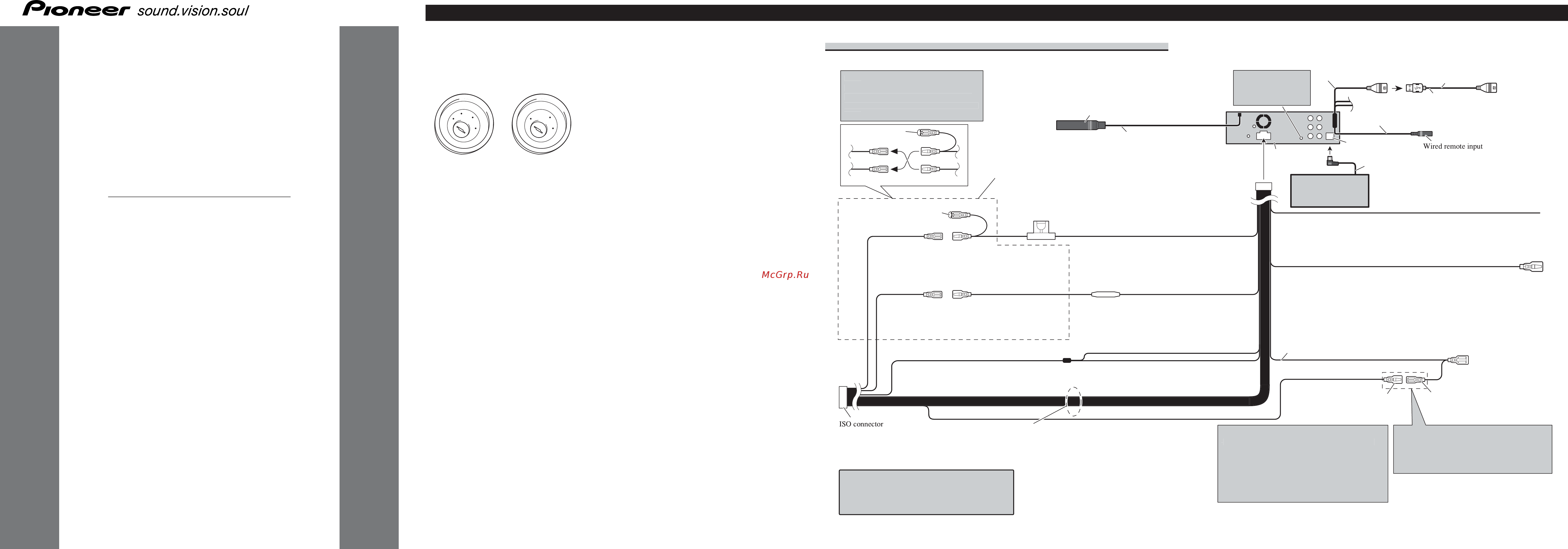
Pioneer sound vision sou I Connecting the Units Note Wien this unit is installed in a vehicle without ACC accessory position on the ignition switch red cable must be wired to the terminal that can detect the operation of the ignition key Otherwise battery drain may result DVH P500UB Printed in Thailand Напечатано в Таиланде CRD4326 A N RE KMMNX 07L00000 ACC position No ACC position Use this unit in other than the following condi tions could result in fire or malfunction Vehicles with a 12 volt battery and negative grounding Speakers with 50 W output value and 4 ohm to 8 ohm impedance value To prevent short circuit overheating or malfunc tion be sure to follow the directions below Disconnect the negative terminal of the battery before installation Secure the wiring with cable clamps or adhe sive tape To protect the wiring wrap adhesive tape around them where they lie against metal parts Place all cables away from moving parts such as gear shift and seat rails Place all cables away from hot places such as near the heater outlet Do not pass the yellow cable through a hole into the engine compartment to connect to a battery Cover any disconnected cable connectors with insulating tape Do not remove RCA caps if RCA cables are not used Do not shorten any cables Never cut the insulation of the power cable of this unit in order to share the power to other equipment Current capacity of the cable is limited Use a fuse of the rating prescribed Never wire the speaker negative cable directly to ground Never band together multiple speaker s nega tive cables ENGLISH Control signal is output through blue white cable when this unit is powered on Connect it to an external power amp s system remote control or the vehicle s auto antenna relay control terminal max 300 mA 12 V DC If the vehicle is equipped with a glass antenna connect it to the antenna booster power supply terminal Never connect blue white cable to external power amp s power terminal Also never connect it to the power terminal of the auto antenna Otherwise battery drain or malfunction may result IP BUS connectors are color coded Be sure to connect connectors of the same color Black cable is ground This cable and other prod uct s ground cable especially high current prod ucts such as power amp must be wired separate ly Otherwise fire or malfunction may result if they are accidentally detached Power cable connection AUX jack 3 5 0 Note Depending on the kind of vehicle the function of 3 and 5 may be different In this case be sure to connect 2 to 5 and 4 to 3 20 cm Use a mini plug cable to connect with auxiliary device 1 5 m Tj ЗЭт KE USB cable Connect to separately sold USB device Antenna jack 15 cm 15 cm 1 his product IP BUS input Blue Wired remote input Hard wired remote control adaptor can be connected sold separately i IP BUS cable Connect leads of the same color to each other Capii Do not remove cap if this terminal is not in use Multi CD player sold separately FusedO A Yellow 3s Back up or accessory Yellow 2s Connect to the constant 12 V supply terminal Red 5 Accessory or back up Red 4s Connect to terminal controlled by ignition switch 12 V DC Yellow black If you use an equipment with Mute function wire this lead to the Audio Mute lead on that equipment If not keep the Audio Mute lead free of any connections Violet white Of the two lead wires connected to the back lamp connect the one in which the voltage changes when the gear shift is in the REVERSE R position For details refer to When connecting w ith a rear view camera Fuse resistor Blue white Connect to system control terminal of the power amp max 300 mA 12 V DC Black chassis ground Connect to a clean paint free metal location Blue white 6 1 ISO connector Note In some vehicles the ISO connector may be divided into two In this case be sure to connect to both connectors When you connect the separately sold multi channel processor DEQ P66IX to this unit do not connect anything to the speaker leads and system remote control blue white Speaker leads White Front left White black Front left Gray Front right Gray black Front right Green Rear left or subwoofer Green black Rear left or subwoofer Violet Rear right or subwoofer Violet black Rear right or subwoofer Notes Change the initial setting of this unit refer to the Operation Manual The subwoofer output of this unit is monaural When using a subwoofer of 70 W 2 2 be sure to connect with Violet and Violet black leads of this unit Do not connect anything with Green and Green black leads Blue white 7 Connect to auto antenna relay control terminal max 300 mA 12 V DC The pin position of the ISO connector will differ depends on the type of vehicle Connect 6 and 7 when Pin 5 is an antenna control type In another type of vehicle never connect 6 and 7