
Gigabyte GA-8IPE1000 Pro2-W Инструкция по эксплуатации онлайн
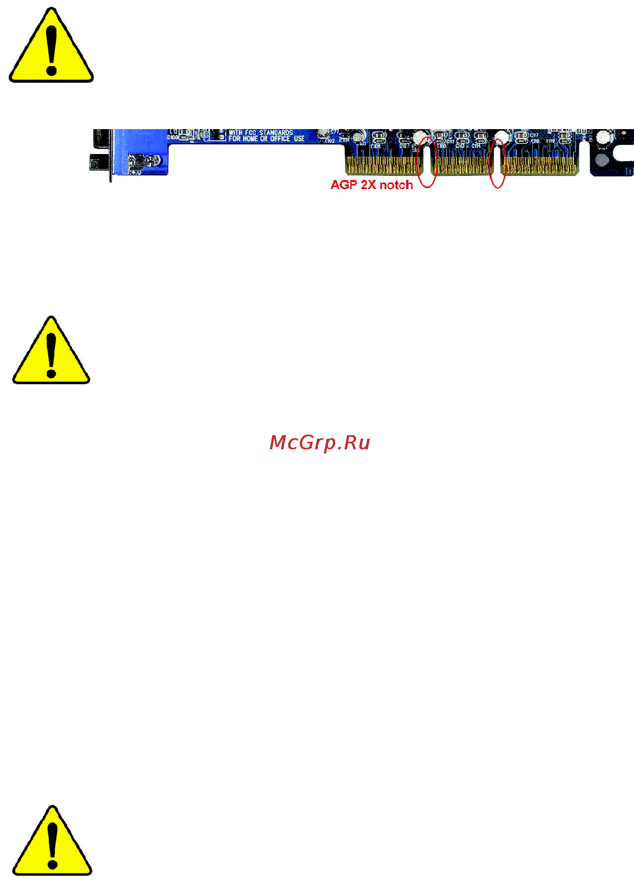
When you installing AGP card, please make sure the following
notice is fully understood and practiced. If your AGP card has
"AGP 4X/8X (1.5V) notch"(show below), please make sure your
AGP card is AGP 4X/8X (1.5V).
Caution: AGP 2X card is not supported by Intel
®
845(GE/PE) / 845(E/
G) / 850(E) / E7205 / 865(G/PE/P) / 875P. You might experience system
unable to boot up normally. Please insert an AGP 4X/8X card.
Example 1: Diamond Vipper V770 golden finger is compatible with 2X/4X
mode AGP slot. It can be switched between AGP 2X(3.3V) or 4X(1.5V)
mode by adjusting the jumper. The factory default for this card is
2X(3.3V). The GA-8IPE1000 Series (or any AGP 4X/8X only)
motherboards might not function properly, if you install this card without
switching the jumper to 4X(1.5V) mode in it.
Example 2: Some ATi Rage 128 Pro graphics cards made by "Power Color",
the graphics card manufacturer & some SiS 305 cards, their golden finger
is compatible with 2X(3.3V)/4X(1.5V) mode AGP slot, but they support 2X
(3.3V) only. The GA-8IPE1000 Series (or any AGP 4X/8X only)
motherboards might not function properly, If you install this card in it.
Note : Although Gigabyte's AG32S(G) graphics card is based on ATi Rage
128 Pro chip, the design of AG32S(G) is compliance with AGP 4X(1.5V)
specification. Therefore, AG32S(G) will work fine with Intel
®
845(GE/PE) /
845(E/G) / 850(E) / E7205 / 865(G/PE/P) / 875P based motherboards.
Before you install PCI cards, please remove the Dual BIOS label from
PCI slots if there is one.
AGP 4X/8X notch
Содержание
- Declaration of conformity 3
- Declare that the product description of the apparatus system installation to which it refers 3
- G b t technology träding gmbh ausschlager weg 41 1f 20537 hamburg germany 3
- In accordance with 89 336 eec emc directive 3
- Mother board ga 8ipe1000 pro ga 8ipe1000 ga 8ipe1000 l ga 8ipe1000 pro2 is in conformity with reference to the specification under which conformity is declared 3
- Timmy huang 3
- We manufacturer importer full address 3
- Declaration of conformity 4
- Ga 8ipe1000 series p4 titan series motherboard 5
- User s manual 5
- Chapter 1 introduction 6
- Chapter 2 hardware installation process 11 6
- Chapter 3 bios setup 7 6
- English 6
- Table of content 6
- Warning 6
- Chapter 4 technical reference 5 7
- Chapter 5 appendix 1 7
- English 7
- English 8
- Installing the motherboard to the chassis 8
- Warning 8
- Chapter 1 introduction 9
- English 9
- Features summary 9
- English 10
- For ga 8ipe1000 l only 10
- For ga 8ipe1000 pro only 10
- For ga 8ipe1000 pro2 only 10
- English 11
- For ga 8ipe1000 pro only 11
- For ga 8ipe1000 pro2 only 11
- 8 ga 8ipe1000 series motherboard 12
- English 12
- For ga 8ipe1000 l only 12
- For ga 8ipe1000 pro only 12
- For ga 8ipe1000 pro2 only 12
- Ga 8ipe1000 pro pro2 12
- Ga 8ipe1000 series motherboard layout 12
- Hyper threading 12
- Nb_fan connector 12
- Note if the northbridge on the motherboard has a fan sink then the motherboard contains a 12
- P4 titan 12
- Block diagram 13
- English 13
- For ga 8ipe1000 l only 13
- For ga 8ipe1000 pro only 13
- For ga 8ipe1000 pro2 only 13
- English 14
- Chapter 2 hardware installation process 15
- English 15
- Actuation lever 16
- Angling the 16
- English 16
- If you do not match the cpu socket pin 1 and cpu cut edge well it will cause improper installation please change the insert orientation 16
- Pin1 indicator 16
- Please make sure the cpu type is supported by the motherboard 16
- Rod to 6 16
- Socket 16
- Step 1 1 cpu installation 16
- Step 1 install the central processing unit cpu 16
- English 17
- Step 1 2 cpu cooling fan installation 17
- Before installing the processor and heatsink adhere to the following warning when ram_led is on do not install remove dimm from socket please note that the dimm module can only fit in one direction due to the one notches wrong orientation will cause improper installation please change the insert orientation 18
- Between sockets 18
- English 18
- Step 2 install memory modules 18
- The motherboard has 4 dual inline memory module dimm sockets the bios will automatically detects memory type and size to install the memory module just push it vertically into the dimm socket the dimm module can only fit in one direction due to the notch memory size can vary 18
- 15 hardware installation process 19
- English 19
- Figure 1 dual channel technology ds double side ss single side 19
- Figure 2 don t operate dual channel technology ds double side ss single side 19
- Please note that those types not in the tables will not boot up 19
- Two ddr memory modules are installed the same memory size and type the dual channel technology will operate when two memory modules are inserted individually into channel a and b if you install two memory modules in the same channel the dual channel technology will not operate 3 three ddr memory modules are installed please note that the dual channel technology will not operate when three ddr memory modules are installed part of them will not be detected 4 four ddr memory modules are installed if you install four memory modules at the same time the dual channel technology will operate only when those modules have the same memory size and type 19
- We ll strongly recommend our user to slot two ddr memory modules into the dimms with the same color in order for dual channel technology to work the following tables include all memory installed combination types 19
- Ddr introduction 20
- English 20
- Established on the existing sdram infrastructure ddr double data rate memory is a high performance and cost effective solution that allows easy adoption for memory vendors oems and system integrators ddr memory is a great evolutionary solution for the pc industry that builds on the existing sdram architecture yet make the awesome advances in solving the system performance bottleneck by doubling the memory bandwidth nowadays with the highest bandwidth of 3 gb s of ddr400 memory and complete line of ddr400 333 266 200 memory solutions ddr memory is the best choice for building high performance and low latency dram subsystem that are 20
- Suitable for servers workstations and full range of desktop pcs 20
- Agp card 21
- English 21
- Read the related expansion card s instruction document before install the expansion card into the computer 2 remove your computer s chassis cover necessary screws and slot bracket from the computer 3 press the expansion card firmly into expansion slot in motherboard 4 be sure the metal contacts on the card are indeed seated in the slot 5 replace the screw to secure the slot bracket of the expansion card 6 replace your computer s chassis cover 7 power on the computer if necessary setup bios utility of expansion card from bios 8 install related driver from the operating system 21
- Step 3 install expansion cards 21
- English 22
- For ga 8ipe1000 l only 22
- For ga 8ipe1000 pro only 22
- For ga 8ipe1000 pro2 only 22
- Ps 2 keyboard and ps 2 mouse connector 22
- Step 4 1 i o back panel introduction 22
- Step 4 connect ribbon cables cabinet wires and power 22
- Supply 22
- Usb lan connector 22
- Audio connectors 23
- English 23
- If you want the detail information for 2 4 6 channel audio setup installation please refer to page 78 23
- Parallel port and serial ports coma comb 23
- English 24
- Step 4 2 connectors jumper setting introduction 24
- 21 hardware installation process 25
- Ac power cord should only be connected to your power supply unit after atx power cable and other related devices are firmly connected to the mainboard 25
- Atx atx power 25
- Atx_12v 12v power connector 25
- English 25
- This connector atx _12v suppliesthe cpu operation voltage vcore if this atx_ 12v connector is not connected system cannot boot 25
- 22 ga 8ipe1000 series motherboard 26
- Cpu_fan cpu fan connector 26
- English 26
- Please note a proper installation of the cpu cooler is essential to prevent the cpu from running under abnormal condition or damaged by overheating the cpu fan connector supports max current up to 600 ma 26
- Sys_fan system fan connector 26
- This connector allows you to link with the cooling fan on the system case to lower the system temperature 26
- 23 hardware installation process 27
- English 27
- For ga 8ipe1000 pro only 27
- For ga 8ipe1000 pro2 only 27
- If you installed wrong direction the chip fan will not work sometimes will damage the chip fan usually black cable is gnd note if the northbridge on the motherboard has a fan sink then the motherboard contains a 27
- Nb_fan 27
- Nb_fan connector 27
- Pwr_fan power fan connector 27
- This connector allows you to link with the cooling fan on the system case to lower the system temperature 27
- English 28
- Fdd floppy connector 28
- Ide1 ide2 ide1 ide2 connector 28
- English 29
- Pwr_led 29
- Ram_led 29
- 26 ga 8ipe1000 series motherboard 30
- 2x_det 30
- English 30
- F_panel 2x10 pins connector 30
- Please connect the power led pc peaker reset switch and power switch etc of your chassis front panel to the f_panel connector according to the pin assignment above 30
- When an agp 2x 3 v card is installed the 2x_det will light up indicating a nonsupported graphics card is inserted informing users that system might not boot up normally due to agp 2x 3 v is not supported by the chipset 30
- 27 hardware installation process 31
- Bat battery 31
- Caution 31
- Danger of explosion if battery is incorrectly replaced replace only with the same or equivalent type recommended by the manufacturer dispose of used batteries according to the 31
- English 31
- F_audio f_audio connector 31
- If you want to erase cmos 1 turn off the computer and unplug the power cord 2 remove the battery wait for 30 second 3 re install the battery 4 plug the power cord and turn on the computer 31
- If you want to use front audio connector you must remove 5 6 9 10 jumper in order to utilize the front audio header your chassis must have front audio connector also please make sure the pin assigment on the cable is the same as the pin assigment on the mb header to find out if the chassis you are buying support front audio connector please contact your dealer please note you can have the alternative of using front audio connector or of using rear audio connector to play sound 31
- Manufacturer s instructions 31
- 28 ga 8ipe1000 series motherboard 32
- Cd_in cd in black 32
- Connect cd rom or dvd rom audio out to the connector 32
- English 32
- Please contact your nearest dealer for optional sur_cen cable 32
- Sur_cen 32
- 29 hardware installation process 33
- Aux_in aux in connector 33
- Connect other device such as pci tv tunner audio out to the connector 33
- English 33
- Spdif_io spdif in out 33
- The spdif output is capable of providing digital audio to external speakers or compressed ac3 data to an external dolby digital decoder use this feature only when your stereo system has digital input function use spdif in feature only when your device has digital output function be careful with the polarity of the spdif_io connector check the pin assignment carefully while you connect the spdif_io cable incorrect connection between the cable and connector will make the device unable to work or even damage it for optional spdif_io cable please contact your local dealer 33
- 30 ga 8ipe1000 series motherboard 34
- Be careful with the polarity of the front usb connector check the pin assignment while you connect the front usb cable please contact your nearest dealer for optional front usb cable be careful with the polarity of the f_usb connector check the pin assignment carefully while you connect the f_usb cable incorrect connection between the cable and connector will make the device unable to work or even damage it for optional f_usb cable please contact your local dealer 34
- English 34
- F_ usb1 f_usb2 front usb connector yellow 34
- Ir_cir 34
- Make sure the pin 1 on the ir device is aling with pin one the connector to enable the ir cir function on the board you are required to purchase an option ir cir module for detail information please contact your autherized giga byte distributor to use ir function only please connect ir module to pin1 to pin5 be careful with the polarity of the ir cir connector check the pin assignment carefully while you connect the ir cir cable incorrect connection between the cable and connector will make the device unable to work or even damage it for optional ir cir cable please contact your local dealer 34
- 31 hardware installation process 35
- English 35
- Game game connector 35
- Info_link 35
- This connector allows you to connect some external devices to provide you extra function 35
- This connector supports joystick midi keyboard and other relate audio devices 35
- 32 ga 8ipe1000 series motherboard 36
- English 36
- F1_1394 ieee 1394 connector 36
- F2_1394 ieee 1394 connector 36
- For ga 8ipe1000 pro only 36
- For ga 8ipe1000 pro2 only 36
- Please note serial interface standard set by institute of electrical and electronics engineers which has features like high speed high bandwidth and hot plug be careful with the polarity of the ieee1394 connector check the pin assignment carefully while you connect the ieee1394 cable incorrect connection between the cable and connector will make the device unable to work or even damage it for optional ieee1394 cable please contact your local dealer 36
- 33 hardware installation process 37
- Ci case open 37
- English 37
- Sata0 sata1 serial ata connector 37
- This 2 pin connector allows your system to enable or disable the case open item in bios if the system case begin remove 37
- You can connect the serial ata device to this connector it provides you high speed transfer rates 150mb sec 37
- Close normal 38
- Clr_pwd 38
- English 38
- Open clear password 38
- English 39
- English 40
- Chapter 3 bios setup 41
- Control 41
- English 41
- Entering 41
- For ga 8ipe1000 pro only 41
- For ga 8ipe1000 pro2 only 41
- Advanced bios features 42
- English 42
- For example bios ver 8ipe1000 pro2 f1 42
- For ga 8ipe1000 pro only 42
- For ga 8ipe1000 pro2 only 42
- Getting help 42
- If you can t find the setting you want please press ctrl f1 to 42
- Main menu 42
- Search the advanced option widden 42
- Standard cmos features 42
- Status page setup menu option page setup menu 42
- The main menu 42
- The on line description of the highlighted setup function is displayed at the bottom of the screen 42
- This setup page includes all the items in standard compatible bios 42
- This setup page includes all the items of award special enhanced features 42
- To accept or enter the sub menu 42
- English 43
- English 44
- For ga 8ipe1000 pro only 44
- For ga 8ipe1000 pro2 only 44
- Standard cmos features 44
- Computer 45
- Drive a drive b 45
- English 45
- Ide primary master slave ide secondary master slave 45
- Note that the specifications of your drive must match with the drive table the hard disk will not work properly if you enter improper information for this category 45
- Such information should be provided in the documentation form your hard disk vendor or the system manufacturer 45
- The category identifies the types of floppy disk driv e a or drive b that has been installed in the 45
- The category identifies the types of hard disk from drive c to f that has been installed in the computer there are two types auto type and manual type manual type is user definable auto type which will automatically detect hdd type 45
- The time is calculated base on the 24 hour military time clock for example 1 p m is 13 00 00 45
- Base memory 46
- English 46
- Extended memory 46
- Floppy 3 mode support for japan area 46
- Halt on 46
- Memory 46
- The bios determines how much extended memory is present during the post 46
- The category determines whether the computer will stop if an error is detected during power up 46
- The category is display only which is determined by post power on self test of the bios 46
- The post of the bios will determine the amount of base or conventional memory installed in the system 46
- The value of the base memory is typically 512 k for systems with 512 k memory installed on the motherboard or 640 k for systems with 640 k or more memory installed on the motherboard 46
- This is the amount of memory located above 1 mb in the cpu s memory address map 46
- Advanced bios features 47
- English 47
- First second third boot device 47
- For ga 8ipe1000 pro only 47
- For ga 8ipe1000 pro2 only 47
- Hard disk boot priority 47
- Pentiu 47
- Processor with ht technology 47
- System will detect automatically and show up when you install the inte 47
- Cpu hyper threading 48
- English 48
- Password check 48
- System the system will not boot and will not access to setup page if the correct 48
- English 49
- For ga 8ipe1000 l only 49
- For ga 8ipe1000 pro only 49
- For ga 8ipe1000 pro2 only 49
- Integrated peripherals 49
- English 50
- On chip primary pci ide 50
- On chip sata 50
- On chip secondary pci ide 50
- Sata port0 configure as 50
- Sata port1 configure as 50
- Usb controller 50
- Ac97 audio 51
- English 51
- For ga 8ipe1000 l only 51
- For ga 8ipe1000 pro only 51
- For ga 8ipe1000 pro2 only 51
- Onboard h w 139 51
- Onboard h w lan 51
- Onboard lan boot rom 51
- Usb 2 controller 51
- Usb keyboard support 51
- Usb mouse support 51
- English 52
- Onboard parallel port 52
- Onboard serial port 1 52
- Onboard serial port 2 52
- This item allows you to determine which infra red ir function of onboard i o chip 52
- Uart mode select 52
- Ur2 duplex mode 52
- Cir port address 53
- Cir port irq 53
- Ecp mode use dma 53
- English 53
- Game port address 53
- Midi port address 53
- Midi port irq 53
- Parallel port mode 53
- Acpi suspend type 54
- English 54
- For ga 8ipe1000 pro only 54
- For ga 8ipe1000 pro2 only 54
- Off by power button 54
- Power led in s1 state 54
- Power management setup 54
- Ac back function 55
- English 55
- Kb power on password 55
- Modemringon wakeonlan 55
- Pme event wake up 55
- Power on by keyboard 55
- Power on by mouse 55
- Resume by alarm 55
- English 56
- For ga 8ipe1000 pro only 56
- For ga 8ipe1000 pro2 only 56
- Pci 1 pci 5 irq assignment 56
- Pci 2 irq assignment 56
- Pci 3 irq assignment 56
- Pci 4 irq assignment 56
- Pnp pci configurations 56
- Case opened 57
- Current voltage v vcore ddr25v 3 v 5v 12v 57
- English 57
- For ga 8ipe1000 pro only 57
- For ga 8ipe1000 pro2 only 57
- Pc health status 57
- Reset case open status 57
- Cpu fan fail warning 58
- Cpu smart fan control 58
- Cpu warning temperature 58
- Current cpu power 58
- Current cpu temperature 58
- English 58
- For ga 8ipe1000 pro only 58
- For ga 8ipe1000 pro2 only 58
- Power fan fail warning 58
- System fan fail warning 58
- System fan speed rpm 58
- Cpu clock ratio 59
- English 59
- For ga 8ipe1000 pro only 59
- For ga 8ipe1000 pro2 only 59
- Frequency voltage control 59
- Those items will be available when cpu host clock control is set to enabled 59
- Agp pci src fixed 60
- Cpu host clock control 60
- Cpu host frequency 60
- English 60
- Memory frequency for 60
- Memory frequency mhz 60
- Agp overvoltage control 61
- Agp pci src frequency mhz 61
- Cpu voltage control 61
- Dimm overvoltage control 61
- English 61
- Normal cpu vcore 61
- English 62
- For ga 8ipe1000 pro only 62
- For ga 8ipe1000 pro2 only 62
- German simplified chinese traditional chinese 62
- Multi language is supports 7 languages there are english japanese french spanish 62
- Select languag 62
- Select language 62
- English 63
- Fail safe defaults contain the most appropriate values of the system parameters that allow minimum system performance 63
- For ga 8ipe1000 pro only 63
- For ga 8ipe1000 pro2 only 63
- Load fail safe defaults 63
- Load fail safe defaults y n y 63
- English 64
- For ga 8ipe1000 pro only 64
- For ga 8ipe1000 pro2 only 64
- Load optimized defaults 64
- Load optimized defaults y n y 64
- Selecting this field loads the factory defaults for bios and chipset features which the system automatically detects 64
- English 65
- Enter password 65
- For ga 8ipe1000 pro only 65
- For ga 8ipe1000 pro2 only 65
- If y ou select system at passw ord c heck in advance bios features menu you will be prompted for the password every time the system is rebooted or any time you try to enter setup menu 65
- If you select setup at password check in advance bios features menu you will be prompted only when you try to enter setup 65
- Set supervisor user password 65
- Supervisor password and a user password when disabled anyone may access all bios setup program function when enabled the supervisor password is required for entering the bios setup program and having full configuration fields the user password is required to access only basic items 65
- The bios setup program allows you to specify two separate passwords 65
- To abort the selection and not enter a password 65
- When you are prompted to enter password a message password disabled will appear to confirm the password being disabled once the password is disabled the system will boot and you can enter setup freely 65
- When you select this function the following message will appear at the center of the screen to assist you in creating a password 65
- English 66
- For ga 8ipe1000 pro only 66
- For ga 8ipe1000 pro2 only 66
- Save exit setup 66
- Save to cmos and exit y n y 66
- Type n will return to setup utility 66
- Type y will quit the setup utility and save the user setup value to rtc cmos 66
- English 67
- Exit without saving 67
- For ga 8ipe1000 pro only 67
- For ga 8ipe1000 pro2 only 67
- Quit without saving y n n 67
- English 68
- Chapter 4 technical reference 69
- English 69
- Gigabyte announces bios windows bios live update utility 69
- Introduction 69
- Revision history 69
- Easy tun 70
- Easytune 4 carries on the heritage so as to pave the way for future generations 70
- English 70
- Gigabyte announces easytun 70
- Introduction 70
- Windows based overclocking utility 70
- English 71
- Face wizar 71
- For ga 8ipe1000 pro only 71
- For ga 8ipe1000 pro2 only 71
- Utilities installation 71
- A what is dual bios technology 72
- B how to use dual bios and q flash utility 72
- Dual bios means that there are two system bios rom on the motherboard one is the main bios and the other is backup bios under the normal circumstances the system works on the main bios if the main bios is corrupted or damaged the backup bios can take over while the 72
- English 72
- Enter dual bios 72
- Flash bios method introduction 72
- For ga 8ipe1000 pro only 72
- For ga 8ipe1000 pro2 only 72
- Method 1 dual bios 72
- Q flash 72
- Q flash utility y n y 72
- System is powered on this means that your pc will still be able to run stably as if nothing has happened in your bios 72
- To enter flash utility 72
- Boot from main bios default backup bios 73
- English 73
- Wide range protection disable default enable 73
- Auto recovery enable default disable 74
- Bios recovery backup to main 74
- Bios recovery main to backup 74
- Copy main rom data to backup 74
- English 74
- Halt on error disable default enable 74
- Keep dmi data enable default disable 74
- Load default settings 74
- Save settings to cmos 74
- C what is q flash utility 75
- D how to use q flash load main bios from floppy load backup bios from floppy 75
- English 75
- Control keys 76
- English 76
- Save main bios to floppy save backup bios to floppy 76
- Answer 77
- Dualbio 77
- English 77
- I q what is dualbio 77
- Technology 77
- Technology faq 77
- What s dualbio 77
- Answer 78
- English 78
- Ii q why does anyone need a motherboard with dualbio 78
- Iii q how does dualbio 78
- Technology 78
- Technology work answer 78
- Answer 79
- English 79
- Iv q who needs dualbio 79
- Technology 79
- English 80
- Method 2 bios utility 80
- English 81
- English 82
- Function 82
- Revision history 2 4 6 channel audio function introuction 82
- Stereo speakers connection and settings 82
- The installation of windows 98se 2k me xp is very simple please follow next step to install the 82
- Channel analog audio output mode 83
- English 83
- Basic 6 channel analog audio output mode 84
- English 84
- English 85
- Basic advanced 6 channel analog audio output mod 86
- English 86
- A spdif output device is available on the 87
- Connecting port 87
- English 87
- Motherboard cable with rear bracket is provided and could link to the spdif output connector as picture for the further linkage to decoder rear bracket provides coaxial cable and fiber 87
- Spdif output device optional device 87
- Auto detecting 88
- English 88
- Introduction of audio connectors 88
- Jack sensing introuction 88
- Jack sensing provides audio connectors error detection function 88
- English 89
- Manual setting 89
- English 90
- Uaj introuction 90
- English 91
- Boot from cd 92
- English 92
- F9 for xpress recovery 92
- How to use the xpress recovery 92
- What is xpress recovery 92
- Xpress recovery introduction 92
- Bmp mode 93
- Directed to bmp mode by pressing f9 in the bootup screen 93
- English 93
- Enter key to enter the menu 93
- If you ever entered xpress recovery by booting from cd rom you ll still be 93
- Text mode 93
- You can highlight the item by using the arrows keys on your keyboard and 93
- English 94
- Chapter 5 appendix 95
- English 95
- Install chipset driver 95
- Install drivers 95
- Revision history 95
- English 96
- For ga 8ipe1000 l only 96
- For ga 8ipe1000 pro only 96
- For ga 8ipe1000 pro2 only 96
- Item description 96
- English 97
- Software application 97
- English 98
- English 99
- English 100
- English 101
- English 102
- Appendix 99 103
- English 103
- If you encounter any trouble during boot up please follow the troubleshooting 103
- Procedures 103
- Troubleshooting 103
- 100 ga 8ipe1000 series motherboard 104
- English 104
- If the above procedure unable to solve your problem please contact with your local retailer or national distributor for help or you could submit your question to the service mail via gigabyte website technical support zone http www gigabyte com tw the appropriate response will be provided asap 104
- English 105
- Technical support rma sheet 105
- Acronyms 106
- English 106
- English 107
- English 108
- English 109
- English 110
- English 111
- 108 ga 8ipe1000 series motherboard 112
- Contact us 112
- Contact us via the information in this page all over the world 112
- English 112
Похожие устройства
- Ballu KFR-25GWE Инструкция по эксплуатации
- Rover RoverMedia Aria E3 Инструкция по эксплуатации
- Thermos F4000FL6 355 ml Инструкция по эксплуатации
- Ballu KFR-2101GWE Инструкция по эксплуатации
- Gigabyte GA-8IDML-C Инструкция по эксплуатации
- Yamaha PSR-S900 Инструкция по эксплуатации
- Thermos IS4560BT6 D/B Инструкция по эксплуатации
- Ballu KF-1802GWE Инструкция по эксплуатации
- Gigabyte GA-8ID533 (rev. 1.0) Инструкция по эксплуатации
- Bosch WAA12160ME Инструкция по эксплуатации
- Samsung I9295 Galaxy S4 Activ Grey Инструкция по эксплуатации
- Gigabyte GA-8ID533 (rev. 1.1) Инструкция по эксплуатации
- Ballu KFR-8202GWE Инструкция по эксплуатации
- Bork TV SPR 2560 ** Инструкция по эксплуатации
- Samsung I9295 Galaxy S4 Activ Blue Инструкция по эксплуатации
- Gigabyte GA-8ID2003 Инструкция по эксплуатации
- Ballu BMSR-18H Инструкция по эксплуатации
- Scarlett SC-983 Инструкция по эксплуатации
- Thermos 183317 JMK 500B Инструкция по эксплуатации
- Gigabyte GA-8I875 Ultra Инструкция по эксплуатации