
Delta Electronics DRS-24V30W1AZ Инструкция по эксплуатации(ENG) онлайн
0
10
20
30
40
50
60
70
80
90
100
110
-20 -15 -10 -5 0 5 10 15 20 25 30 35 40 45 50 55 60 65 70
Percentage of Max Load (%)
Surrounding Air Temperature
(
o
C)
1. Safety instructions
• Switch main power off before connecting or disconnecting the device. Risk of
explosion!
• To guarantee sufcient convection cooling, keep a distance of > 80mm above and
below the device as well as a lateral distance of 25mm to other units.
• Note that the enclosure of the device can become very hot depending on the
ambient temperature and load of the power supply. Risk of burns!
• The main power must be turned off before connecting or disconnecting the wires to
the terminals!
• Do not introduce any objects into the unit!
• Dangerous voltage present for at least 5 minutes after disconnecting all sources of
power.
• The power supplies unit should be installed in minimum IP54 rated enclosure.
• The power supplies are built in units and must be installed in a cabinet or room
(condensation free environment and indoor location) that is relatively free of
conductive contaminants.
• CAUTION:
“FOR USE IN A CONTROLLED ENVIRONMENT”.
2. Device description (Fig. 1)
(1) Input terminal block connector
(2) Output terminal block connector
(3) DC voltage adjustment potentiometer
(4) DC OK LED (green)
(5) Universal mounting rail system
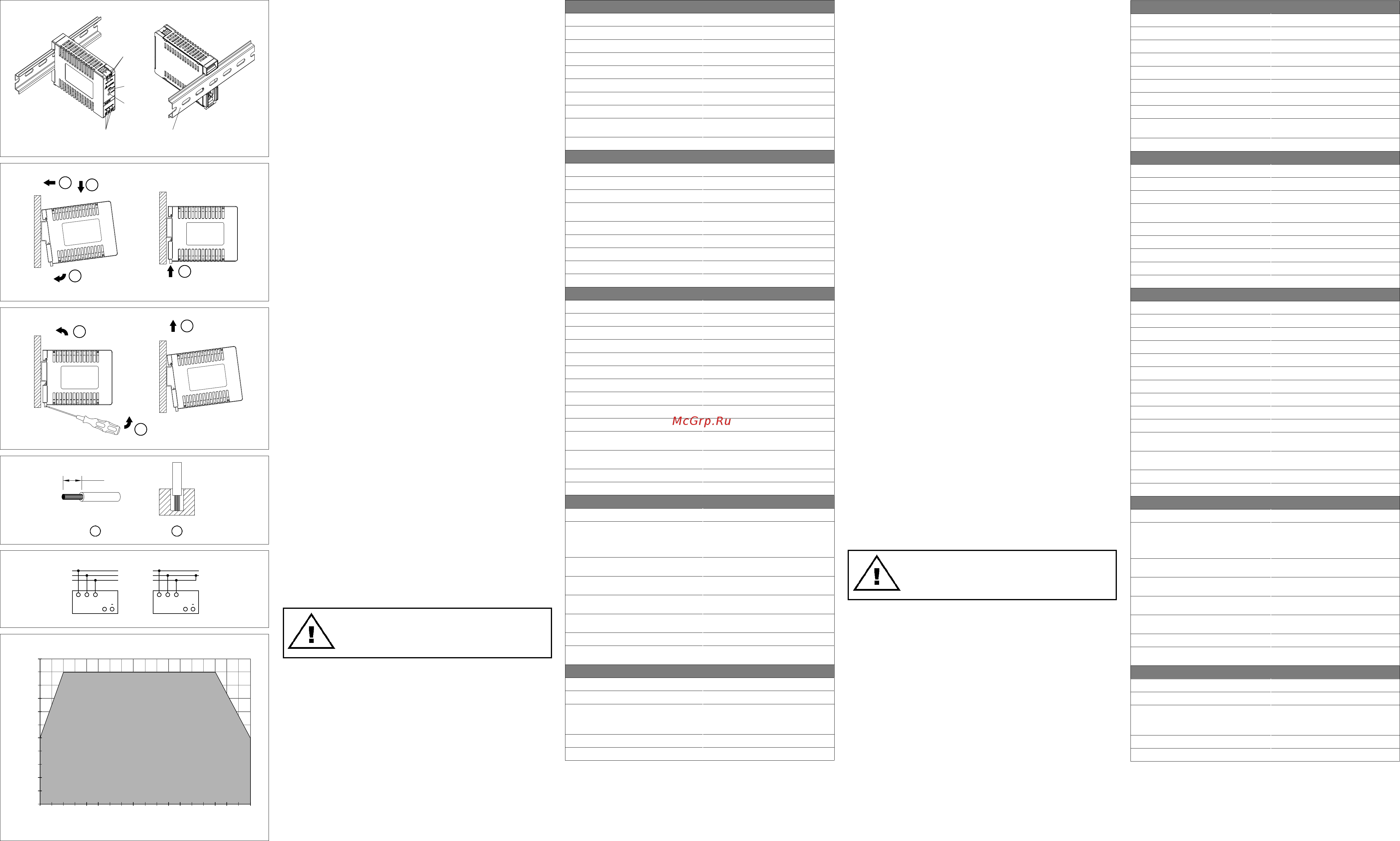
3. Mounting (Fig. 2)
The power supply unit can be mounted on 35 mm DIN rails in accordance with
EN60715. The device should be installed with input terminal block on the bottom.
Each device is delivered ready to install.
Snap on the DIN rail as shown in Fig. 2:
1. Tilt the unit slightly upwards and put it onto the DIN rail.
2. Push downwards until stopped.
3. Press against the bottom front side for locking.
4. Shake the unit slightly to ensure that it is secured.
4. Dismounting (Fig. 3)
To uninstall, pull or slide down the latch as shown in Fig. 3. Then, slide the PSU in the
opposite direction, release the latch and pull out the PSU from the rail.
5. Connection
The terminal block connectors allow easy and fast wiring.
User should calculate and select the suitable wire specication (type/quantity/diameter)
according to actual output current. You can use exible (stranded wire) or solid cables
with cross sections 0.13-3.3mm² (AWG 26-12) and torque of 8.05 kgf.cm (7 lb in).
To secure reliable and shock proof connections, the stripping length should be
7mm (see Fig. 4 (1)). Please ensure that wires are fully inserted into the connecting
terminals as shown in Fig. 4 (2).
In accordance to EN60950 / UL60950, exible cables require ferrules.
Use appropriate copper cables designed to 300V, 105°C or more to fulll UL
requirements.
5.1. Input connection (Fig. 1, Fig. 5)
Use L and N connections of input terminal connector (see Fig. 1 (1)) to establish the
100-240Vac connection.
The device has an internal fuse. 5A power circuit breakers are recommended as
backup fuses.
1. Sicherheitsvorschriften
• Schalten Sie die Netzspannung ab, bevor Sie das Gerät an das Netz anschließen
oder es vom Netz trennen. Explosionsgefahr!
• Um eine ausreichende Konvektionskühlung zu gewährleisten, halten Sie oberund
unterhalb des Gerätes einen Abstand von > 80mm ein sowie einen seit lichen
Abstand von 25mm zu anderen Geräten.
• Beachten Sie, dass das Gehäuse des Gerätes sehr heiß werden kann, abhängig
von der Umgebungstemperatur und der Last an der Spannungsversorgung.
Verbrennungsgefahr!
• Verbinden und trennen Sie die Anschlüsse nur, wenn die Spannung abgeschaltet
ist!
• Führen Sie keine Objekte in das Gerät ein!
• Nachdem das Gerät von allen Spannungsquellen getrennt wurde liegt über einen
Zeitraum von mindestens 5 Minuten noch gefährliche Spannung an dem Gerät an.
• Das Netzgerät muss in einem Gehäuse installiert sein, das mindestens der
Schutzklasse IP54 entspricht.
• Die Netzgeräte sind eingebaute Geräte und müssen in einem Schrank oder Raum
(Innenraum ohne Kondensation) installiert werden, der relativ frei von leitenden
Schmutzstof fen ist.
• VORSICHT:
„Zum Einsatz nur im Innenbereich“.
2. Gerätebeschreibung (Abb. 1)
(1) Eingangsklemmen
(2) Ausgangsklemmen
(3) Potentiometer zur Einstellung der DC-Ausgangsspannung
(4) LED „DC OK“ (grün)
(5) Universelles Montageschienensystem
3. Montage (Abb. 2)
Das Netzteil kann auf 35mm DIN-Schienen gemäß EN60715 montiert werden. Das
Gerät sollte mit den Eingangsklemmen nach unten montiert werden.
Jedes Gerät wird installationsfertig geliefert.
Einrasten des Geräts in DIN-Schiene, wie in Abb. 2 dargestellt:
1. Kippen Sie das Gerät leicht nach oben und setzen Sie es auf die DIN-Schiene
auf.
2. Kippen Sie das Gerät jetzt wieder nach unten bis zum Anschlag am unteren Teil
der Schiene.
3. Drücken Sie nun den unteren Teil des Gerätes so fest gegen die Schiene bis das
Gerät auf der Schiene einrastet.
4. Rütteln Sie leicht am Gerät, um zu überprüfen, ob es korrekt eingerastet ist.
4. Demontage (Abb. 3)
Ziehen Sie zur Demontage den Einrasthebel mit einem Schraubendreher nach unten,
wie in Abb. 3 dargestellt. Kippen Sie das Netzteil in die entgegengesetzte Richtung
nach oben, klinken Sie den Einrasthebel aus und nehmen Sie das Netzteil nach oben
von der DIN-Schiene ab.
5. Anschluss
Der Benutzer muss berechnen und Wahlen Sie die entsprechende Spezikation
des Drahtes (Art/Menge/Durchmesser) nach dem tatsächlichen Ausgang Strom. Sie
können exible (feindrähtige Leitung) oder feste Kabel mit einem Querschnitt von 0,13-
3,3mm² (AWG 26-12) und einem Anzugsmoment von 8,05 kgf,cm (7 lb in) verwenden.
Um sichere und stoßfeste Anschlüsse gewährleisten zu können, sollte die
Abisolierlänge 7mm betragen (siehe Abb. 4 (1)). Bitte sorgen Sie dafür, dass die Kabel
vollständig in die Anschlussklemmen eingeführt werden, siehe Abb. 4 (2).
Gemäß EN60950 / UL60950 sind für exible Kabel Aderendhülsen erforderlich.
Verwenden Sie geeignete Kupferkabel für 300V, 105°C oder mehr um die UL zu
erfüllen.
5.1. Anschluss der Eingangsklemmen (Abb. 1, Abb. 5)
Verwenden Sie die Eingangsklemmen L und N (Schutzleiter), um den 100-240Vac-
Anschluss herzustellen. Abb. 5 zeigt den Anschluss an die unterschiedlichen
Netztypen.
Das Gerät verfügt über eine interne Sicherung. Es wird empfohlen eine 5A
Leistungsschutzschaltern zu verwenden.
DEUTSCH
Anleitung
ENGLISH
Installation notes
ENGLISH
Technical data
Input (AC)
Nominal input voltage and frequency 100-240Vac
Voltage range 85-264Vac
Frequency 47-63Hz
Nominal current < 0.80A @ 115Vac, < 0.40A @ 230Vac
Inrush current limitation (+25°C) typ. (cold start) < 60A @ 230Vac
Mains buffering at nominal load (typ.) > 20ms @ 230Vac
Turn-on time < 3 sec. @ 115Vac, < 1.6 sec. @ 230Vac
Internal fuse T 5A L / 250V
Recommended backup fuse:
Power circuit-breaker characteristic
5A
B
Leakage current < 0.5mA @ 240Vac
Output (DC)
Nominal output voltage U
N
/ tolerance 24Vdc ± 1%
Adjustment range of the voltage 21.6-26.4Vdc
Nominal current 1.25A
Derating Refer to Fig. 6
-10°C to -20°C (5% / °C), > 55°C (3.33% / °C) in Vertical
Startup with capacitive loads Max. 3,000µF
Max. power dissipation idling / nominal load approx. 0.5W / 5W
Efciency 88.0% typ. @ 230Vac
PARD (20MHz) (at nominal values) 150mVpp
Parallel operation DRR-20A / DRR-40A
General Data
Type of housing Plastic (PC), enclosed
LED signals Green LED DC OK
MTBF > 700,000 hrs. as per Telcordia
Dimensions (L x W x H) 75mm x 21mm x 89.5mm
Weight 0.10kg
Connection method Screw connection
Stripping length 7mm
Operating temperature (surrounding air temperature) -20°C to +70°C (Refer to Fig. 6)
Storage temperature -40°C to +85°C
Humidity at +25°C, no condensation 5 to 95% RH
Vibration (operating) IEC60068-2-6, Sine Wave: 10-500Hz @ 19.6m/S² (2G
peak); 10 min per cycle, 60 min for X direction
Shock (operating) IEC60068-2-27, Half Sine Wave: 10G for a duration of
11ms, 1 shocks for X direction
Pollution degree 2
Altitude (operating) 2000 Meters
Certication and Standards
Safety entry low voltage SELV (EN60950)
Electrical safety (of information technology equipment) TUV Bauart to EN60950-1
UL/C-UL recognized to UL60950-1 and CSA C22.2
No. 60950-1 (File No. E131881)
CB scheme to IEC60950-1
Limited Power Source (LPS)
Industrial control equipment UL/C-UL listed to UL508 and CSA C22.2 No. 107.1-01
(File No. E338991)
Class 2 Power Supply UL/C-UL recognized to UL60950-1 and CSA C22.2
No. 60950-1
CCC GB9254, GB17625.1 and GB4943.1
仅适用于海拔 2000m 以下地区安全使用
CE In conformance with EMC directive 2004/108/EC and
low voltage directive 2006/95/EC
Immunity EN55024
Emission EN55022, EN61000-6-3, EN61000-6-4 Class B,
EN61000-3-2, EN61000-3-3
Safety and Protection
Current limitation at short-circuits approx. I
surge
= 110-150% of Po
max
typically
Surge voltage protection against internal surge voltages Yes
Isolation voltage:
Input / output
Input / PE
Output / PE
3.0KVac
1.5KVac
0.5KVac
Protection degree IP20
Safety class Class I with PE connection
DEUTSCH
Technische Daten
Eingangskennwerte (AC)
Nennspannung en frequentie 100-240Vac
Spannungsbereich 85-264Vac
Frequenzbereich 47-63Hz
Nennstrom < 0,80A bei 115Vac, < 0,40A bei 230Vac
Einschaltstrombegrenzung (+25°C) typ. (Kaltstart) < 60A bei 230Vac
Netzausfallüberbrückung bei Nennlast (typ.) > 20ms bei 230Vac
Einschaltzeit < 3 sec. bei 115Vac, < 1,6 sec. bei 230Vac
Interne Sicherung T 5A L / 250V
Empfohlene Vorsicherung:
Auslösecharakteristik Leistungsschalter
5A
B
Ableitstrom < 0,5mA @ 240Vac
Ausgangskennwerte (DC)
Nennausgangsspannung U
N
/ Toleranz 24Vdc ± 1%
Einstellbereich der Ausgangsspannung 21,6-26,4VdcVdc
Nennstrom 1,25A
Derating (Leistungsherabsetzung) Leistungsherabsetzung gemäß Abb. 6
-10°C bis -20°C (5% / °C), > 55°C (3,33% / °C) Vertikal
Anlaufen bei Kapazitiven Lasten Max. 3.000µF
Max. Verlustleistung Leerlauf/Nennlast 0,5W / 5W
Wirkungsgrad 88,0% typ. bei 230Vac
PARD (20MHz) (bei Nennwerten) 150mVpp
Parallelschaltbarkeit DRR-20A / DRR-40A
Allgemeine Kennwerte
Gehäusetyp Plastik (PC), geschlossen
LED-Signale Grüne LED „DC OK“
MTBF (mittlere Betriebszeit zwischen Ausfällen) > 700.000 Std., entsprechend Telcordia
Abmessungen (B x H x T) 75mm x 21mm x 89,5mm
Gewicht 0,10kg
Art der Anschlussklemme Schraubanschluss
Abisolierlänge 7mm
Betriebstemperaturbereich (Umgebungstemperatur) -20°C bis +70°C (Leistungsherabsetzung gemäß Abb. 6)
Lagertemperaturbereich -40°C bis +85°C
Luftfeuchte bei +25°C, keine Betauung 5 bis 95% relative Luftfeuchte
Vibration (Betrieb) IEC60068-2-6, Sinus Wellen: 10 bis 500 Hz bei 19,6m/S²
(2g Spitze.); 10 min. pro Zyklus, 60 min. in X Richtung
Stoßfestigkeit (Betrieb) IEC60068-2-27, Halbsinus Wellen: 10g für eine Dauer
von 11 ms, 1 Schocks für X Richtung
Verschmutzungsgrad 2
Höhe (Betrieb) 2000 Meter
Zertizierung und Normen
Schutzkleinspannung SELV (EN60950)
Elektrische Sicherheit (von Einrichtungen der
Informationstechnik)
TUV Bauart nach EN60950-1
UL/C-UL anerkannt nach UL60950-1 und CSA C22.2
Nr. 60950-1 (File Nr. E131881)
Prüfprotokoll und -bericht nach IEC60950-1
Stromquelle begrenzter Leistung (LPS)
Industrielle Regeleinrichtungen UL/C-UL gelistet nach UL508 und CSA C22.2 Nr.107.1-01
(File Nr. E338991)
Class 2 Power Supply UL/C-UL anerkannt nach UL60950-1 und CSA C22.2
Nr. 60950-1
CCC GB9254, GB17625.1 und GB4943.1
仅适用于海拔 2000m 以下地区安全使用
EC In Konformität zur EMV-Richtlinie 2004/108/EC und
Niederspannungsrichtlinie 2006/95/EC
Störfestigkeit EN55024
Emission EN55022, EN 61000-6-3, EN 61000-6-4 Klasse B,
EN61000-3-2, EN61000-3-3
Sicherheit und Schutzeinrichtungen
Strombegrenzung bei Kurzschluss I
Überstrom
= 110-150% der max. Ausgangsleistung
Überspannungsschutz gegen interne Überspannungen Ja
Isolationsspannung
Eingang / Ausgang
Eingang / Schutzleiter
Ausgang / Schutzleiter
3,0KVac
1,5KVac
0,5KVac
Schutzart IP20
Schutzklasse Klasse I mit Schutzleiteranschluss
Figure 6
Figure 2
Figure 3
Figure 4
Figure 1
Figure 5
The internal fuse must not be replaced by the user.
In case of internal defect, return the unit for inspection to
the manufacturer.
5.2. Output connection (Fig. 1 (2))
Use the “+” and “-“ screw connections to establish the 24Vdc connection. The output
provides 24Vdc. The output voltage can be adjusted from 21.6 to 26.4Vdc on the
potentiometer. The green LED DC OK displays correct function of the output (Fig.
1 (4)). The device has a short circuit and overload protection and an over voltage
protection limited to < 34.8Vdc.
5.3. Output characteristic curve
The device functions normal under operating line and load conditions. In the event of
a short circuit or over load the output voltage and current collapses (I
O/L
or I
S/C
is > I
surge
(110-150%)). The secondary voltage is reduced and bounces until short circuit or over
load on the secondary side has been removed.
5.4. Thermal behavior (Fig. 6)
In the case of ambient temperatures:
1. At -10°C to -20°C, the output capacity has to be reduced by 5% per degree
Celsius increase in temperature
2. Above +55°C, the output capacity has to be reduced by 3.33% per degree
Celsius increase in temperature
If the output capacity is not reduced when T
Amb
> 55°C, the device will run into thermal
protection by switching off i.e. device will go in bouncing mode and will recover when
ambient temperature is lowered or load is reduced as far as necessary to keep device
in working condition.
5.2. Anschluss der Ausgangsklemmen (Abb. 1 (2))
Verwenden Sie die Schraubklemmen „+“ und „-“, um den 24Vdc-Anschluss
herzustellen. Am Ausgang stehen 24Vdc zur Verfügung. Die Ausgangsspannung kann
am Potentiometer zwischen 21,6 und 26,4Vdc eingestellt werden. Die grüne LED “DC
OK” zeigt die korrekte Funktion des Ausgangs an (Abb. 1 (4)). Das Gerät verfügt über
einen Kurzschluss-, Überlast- und Überspannungsschutz, der auf 34,8Vdc begrenzt
ist.
5.3. Ausgangskennlinie
Das Gerät funktioniert normal, solange die Netz- und Lastbedingungen im
Betriebsbereich des Geräts liegen. Im Fall eines Kurzschlusses oder einer Überlast
fallen Ausgangsspannung und –strom ab (bei I
Überlast
bzw. I
Kurzschluss
> I
Überstrom
(110-150%)). Die Sekundärspannung wird dabei so lange abgesenkt, bis der
sekundärseitige Kurzschluss oder die Überlast behoben sind.
5.4. Temperaturverhalten (Abb. 6)
Beträgt die Umgebungstemperatur:
1. Bei -10°C bis -20°C, muss die Ausgangsleistung entsprechend dem-
Temperaturanstieg um 5% pro Grad Celsius reduziert werden
2. Über +55°C, muss die Ausgangsleistung entsprechend dem Temperaturanstieg
um 3,33% pro Grad Celsius reduziert werden
Wenn die Ausgangs-Leistung bei einer Umgebungstemperatur von > 55°C nicht
herabgesetzt, löst der thermische Überlastschutz aus und schaltet das Gerät ab. Das
Gerät bleibt dann so lange in diesem Zustand bis die Umgebungstemperatur oder die
Last soweit abgesenkt wurde, dass das Gerät wieder im Normalbetrieb arbeiten kann..
Die interne Sicherung darf nicht vom Anwender ausge-
tauscht werden. Schicken Sie das Gerät im Fall eines
Defekts zur Reparatur zum Hersteller zurück.
Power Derating Curve for PSU in Vertical Mounting
7 mm
1 2
(1)
(2)
(4)
(3)
(5)
1
2
3
4
2
3
1
7 mm
1 2
(1)
(2)
(4)
(3)
(5)
1
2
3
4
2
3
1
7 mm
1 2
(1)
(2)
(4)
(3)
(5)
1
2
3
4
2
3
1
7 mm
1 2
(1)
(2)
(4)
(3)
(5)
1
2
3
4
2
3
1
L
N
PE
L N PE
TN-S
L
PEN
L N PE
TN-C
++
Manual_Sync_24V_30W1P_DRS-24V30W1AZ_Rev.00_241114.indd 1 11/24/2014 5:12:35 PM
Содержание
- 110 150 die sekundärspannung wird dabei so lange abgesenkt bis der sekundärseitige kurzschluss oder die überlast behoben sind 1
- 110 150 the secondary voltage is reduced and bounces until short circuit or over load on the secondary side has been removed 1
- 20 15 10 5 0 5 10 15 20 25 30 35 40 45 50 55 60 65 70 1
- Above 55 c the output capacity has to be reduced by 3 3 per degree 2 above 55 c the output capacity has to be reduced by 3 3 per degree 1
- Abstand von 25mm zu anderen geräten abstand von 25mm zu anderen geräten 1
- Anleitung 1
- Anschluss der ausgangsklemmen abb 1 2 verwenden sie die schraubklemmen und um den 24vdc anschluss herzustellen am ausgang stehen 24vdc zur verfügung die ausgangsspannung kann am potentiometer zwischen 21 6 und 26 4vdc eingestellt werden die grüne led dc ok zeigt die korrekte funktion des ausgangs an abb 1 4 das gerät verfügt über einen kurzschluss überlast und überspannungsschutz der auf 34 8vdc begrenzt ist 1
- Anschluss der benutzer muss berechnen und wahlen sie die entsprechende spezifikation des drahtes art menge durchmesser nach dem tatsächlichen ausgang strom sie können flexible feindrähtige leitung oder feste kabel mit einem querschnitt von 0 13 3 3mm² awg 26 12 und einem anzugsmoment von 8 05 kgf cm 7 lb in verwenden 1
- Anschluss der eingangsklemmen abb 1 abb 5 verwenden sie die eingangsklemmen l und n schutzleiter um den 100 240vac anschluss herzustellen abb 5 zeigt den anschluss an die unterschiedlichen netztypen 1
- Auf auf 1
- Ausgangskennlinie das gerät funktioniert normal solange die netz und lastbedingungen im betriebsbereich des geräts liegen im fall eines kurzschlusses oder einer überlast fallen ausgangsspannung und strom ab bei 1
- Beachten sie dass das gehäuse des gerätes sehr heiß werden kann abhängig von der umgebungstemperatur und der last an der spannungsversorgung 1
- C nicht herabgesetzt löst der thermische überlastschutz aus und schaltet das gerät ab das gerät bleibt dann so lange in diesem zustand bis die umgebungstemperatur oder die last soweit abgesenkt wurde dass das gerät wieder im normalbetrieb arbeiten kann 1
- C the device will run into thermal protection by switching off i e device will go in bouncing mode and will recover when ambient temperature is lowered or load is reduced as far as necessary to keep device in working condition 1
- Caution 1
- Celsius increase in temperature celsius increase in temperature 1
- Conductive contaminants conductive contaminants 1
- Connection the terminal block connectors allow easy and fast wiring 1
- Das gerät verfügt über eine interne sicherung es wird empfohlen eine 5a leistungsschutzschaltern zu verwenden 1
- Das netzgerät muss in einem gehäuse installiert sein das mindestens der schutzklasse ip54 entspricht 1
- Demontage abb 3 ziehen sie zur demontage den einrasthebel mit einem schraubendreher nach unten wie in abb 3 dargestellt kippen sie das netzteil in die entgegengesetzte richtung nach oben klinken sie den einrasthebel aus und nehmen sie das netzteil nach oben von der din schiene ab 1
- Der schiene der schiene 1
- Deutsch 1
- Device description fig 1 1 input terminal block connector 2 output terminal block connector 3 dc voltage adjustment potentiometer 4 dc ok led green 5 universal mounting rail system 1
- Die interne sicherung darf nicht vom anwender ausge tauscht werden schicken sie das gerät im fall eines defekts zur reparatur zum hersteller zurück 1
- Die netzgeräte sind eingebaute geräte und müssen in einem schrank oder raum innenraum ohne kondensation installiert werden der relativ frei von leitenden 1
- Dismounting fig 3 to uninstall pull or slide down the latch as shown in fig 3 then slide the psu in the opposite direction release the latch and pull out the psu from the rail 1
- Do not introduce any objects into the unit dangerous voltage present for at least 5 minutes after disconnecting all sources of power 1
- Drücken sie nun den unteren teil des gerätes so fest gegen die schiene bis das 3 drücken sie nun den unteren teil des gerätes so fest gegen die schiene bis das 1
- Each device is delivered ready to install snap on the din rail as shown in fig 2 1 tilt the unit slightly upwards and put it onto the din rail 1
- English 1
- Figure 1 1
- Figure 2 1
- Figure 3 1
- Figure 4 1
- Figure 5 1
- Figure 6 1
- Führen sie keine objekte in das gerät ein nachdem das gerät von allen spannungsquellen getrennt wurde liegt über einen zeitraum von mindestens 5 minuten noch gefährliche spannung an dem gerät an 1
- Gemäß en60950 ul60950 sind für flexible kabel aderendhülsen erforderlich verwenden sie geeignete kupferkabel für 300v 105 c oder mehr um die ul zu erfüllen 1
- Gerät auf der schiene einrastet gerät auf der schiene einrastet 1
- Gerätebeschreibung abb 1 1 eingangsklemmen 2 ausgangsklemmen 3 potentiometer zur einstellung der dc ausgangsspannung 4 led dc ok grün 5 universelles montageschienensystem 1
- If the output capacity is not reduced when 1
- In accordance to en60950 ul60950 flexible cables require ferrules use appropriate copper cables designed to 300v 105 c or more to fulfill ul requirements 1
- Input connection fig 1 fig 5 use l and n connections of input terminal connector see fig 1 1 to establish the 100 240vac connection 1
- Installation notes 1
- Jedes gerät wird installationsfertig geliefert einrasten des geräts in din schiene wie in abb 2 dargestellt 1 kippen sie das gerät leicht nach oben und setzen sie es auf die din schiene 1
- Kippen sie das gerät jetzt wieder nach unten bis zum anschlag am unteren teil 2 kippen sie das gerät jetzt wieder nach unten bis zum anschlag am unteren teil 1
- Manual_sync_24v_30w1p_drs 24v30w1az_rev 0_241114 indd 1 11 24 2014 5 12 35 pm 1
- Mm above and below the device as well as a lateral distance of 25mm to other units 1
- Mm ein sowie einen seit lichen 1
- Montage abb 2 das netzteil kann auf 35mm din schienen gemäß en60715 montiert werden das gerät sollte mit den eingangsklemmen nach unten montiert werden 1
- Mounting fig 2 the power supply unit can be mounted on 35 mm din rails in accordance with en60715 the device should be installed with input terminal block on the bottom 1
- Note that the enclosure of the device can become very hot depending on the ambient temperature and load of the power supply risk of burns 1
- Output characteristic curve the device functions normal under operating line and load conditions in the event of a short circuit or over load the output voltage and current collapses 1
- Output connection fig 1 2 use the and screw connections to establish the 24vdc connection the output provides 24vdc the output voltage can be adjusted from 21 to 26 vdc on the potentiometer the green led dc ok displays correct function of the output fig 1 4 the device has a short circuit and overload protection and an over voltage protection limited to 34 vdc 1
- Percentage of max load 1
- Press against the bottom front side for locking 3 press against the bottom front side for locking 1
- Push downwards until stopped 2 push downwards until stopped 1
- Rütteln sie leicht am gerät um zu überprüfen ob es korrekt eingerastet ist 4 rütteln sie leicht am gerät um zu überprüfen ob es korrekt eingerastet ist 1
- Safety instructions switch main power off before connecting or disconnecting the device risk of explosion 1
- Schmutzstof fen ist schmutzstof fen ist 1
- Shake the unit slightly to ensure that it is secured 4 shake the unit slightly to ensure that it is secured 1
- Sicherheitsvorschriften schalten sie die netzspannung ab bevor sie das gerät an das netz anschließen oder es vom netz trennen explosionsgefahr 1
- Surrounding air temperature 1
- Technical data 1
- Technische daten 1
- Temperaturanstieg um 5 pro grad celsius reduziert werden temperaturanstieg um 5 pro grad celsius reduziert werden 1
- Temperaturverhalten abb 6 beträgt die umgebungstemperatur 1 bei 10 c bis 20 c muss die ausgangsleistung entsprechend dem 1
- The device has an internal fuse 5a power circuit breakers are recommended as backup fuses 1
- The internal fuse must not be replaced by the user in case of internal defect return the unit for inspection to the manufacturer 1
- The main power must be turned off before connecting or disconnecting the wires to the terminals 1
- The power supplies unit should be installed in minimum ip54 rated enclosure the power supplies are built in units and must be installed in a cabinet or room condensation free environment and indoor location that is relatively free of 1
- Thermal behavior fig 6 in the case of ambient temperatures 1 at 10 c to 20 c the output capacity has to be reduced by 5 per degree 1
- To secure reliable and shock proof connections the stripping length should be 7mm see fig 4 1 please ensure that wires are fully inserted into the connecting terminals as shown in fig 4 2 1
- Um 3 33 pro grad celsius reduziert werden um 3 33 pro grad celsius reduziert werden 1
- Um sichere und stoßfeste anschlüsse gewährleisten zu können sollte die abisolierlänge 7mm betragen siehe abb 4 1 bitte sorgen sie dafür dass die kabel vollständig in die anschlussklemmen eingeführt werden siehe abb 4 2 1
- User should calculate and select the suitable wire specification type quantity diameter according to actual output current you can use flexible stranded wire or solid cables with cross sections 0 3 3 mm² awg 26 12 and torque of 8 5 kgf cm 7 lb in 1
- Verbinden und trennen sie die anschlüsse nur wenn die spannung abgeschaltet ist 1
- Verbrennungsgefahr verbrennungsgefahr 1
- Vorsicht 1
- Über 55 c muss die ausgangsleistung entsprechend dem temperaturanstieg 2 über 55 c muss die ausgangsleistung entsprechend dem temperaturanstieg 1
- 110 150 la tension secondaire diminue puis rebondit jusqu à l élimination du court circuit ou de la surcharge côté secondaire 2
- 3 mm² awg 26 12 2
- 4 dc ok 2
- 55 c 2 55 2
- Appuyez sur la face inférieure de l appareil pour le verrouiller en place 3 appuyez sur la face inférieure de l appareil pour le verrouiller en place 2
- Attention 2
- C l appareil s arrête et passe en mode de protection thermique c est à dire qu il passe en régime de rebondissement et qu il redémarrera lorsque la température ou la charge auront été suffisamment réduites pour rétablir les conditions nominales de fonctionnement 2
- Celsiu 2
- Celsius d accroissement de température celsius d accroissement de température 2
- Cn 安装注意事项 2
- Comportement thermique fig 6 si la température ambiante 1 de 10 c à 20 c la capacité de sortie doit être réduite de 5 par degré celsius 2
- Consignes de sécurité mettez l alimentation générale hors tension avant de connecter ou de déconnecter l appareil danger d explosion 2
- Courbe caractéristique de sortie l appareil fonctionne normalement dans les conditions nominales de l alimentation en cas de court circuit ou de surcharge la tension et l intensité de sortie chutent 2
- D accroissement de la température d accroissement de la température 2
- De 25mm par rapport aux autres appareils de 25mm par rapport aux autres appareils 2
- De einbauanleitung 2
- Delta sync power supply system 1ac 24vdc 1 5a 2
- Description de l appareil fig 1 1 connecteur bornier d entrée 2 connecteur bornier de sortie 3 potentiomètre de réglage de tension continue cc 4 led cc ok verte 5 rail de montage universel 2
- Données techniques 2
- Démontage fig 3 pour démonter l appareil tirez ou faites coulisser le loquet vers le bas comme indiqué à la fig 3 faites coulisser l appareil dans la direction opposée relâchez le loquet et enlevez l appareil du rail 2
- Dépasse 55 c la capacité de sortie doit être réduite de 3 33 par degré 2 dépasse 55 c la capacité de sortie doit être réduite de 3 33 par degré 2
- En cas de défaillance de phase l appareil peut fonctionner en régime non dégradé à capacité nominale 2
- En installation notes 2
- En60715 2
- En60950 ul6095 2
- Fig 1 1 2
- Fig 1 fig 5 2
- Fig 4 1 2
- Fig 4 2 2
- Fr instruction d installation 2
- Français 2
- Instruction d installation 2
- Kgf cm 7 lb in 2
- L appareil est livré prêt à installer encliquetez le sur le rail din comme indiqué à la fig 2 1 inclinez l appareil légèrement vers le haut et placez le sur le rail din 2
- L appareil est équipé d un fusible interne il est recommandé d utiliser un disjoncteur de 5a comme protection redondante du fusible 2
- L utilisateur devra calculer et choisir la spécification du fil appropriée type quantité diamètre en fonction du courant réel vous pouvez utiliser du câble souple conducteurs torsadé ou rigide de section 0 13 3 3mm² max awg 26 12 avec un couple de serrage de 8 05 kgf cm 7 lb in le câble doit être dénudé sur 7mm pour assurer une connexion fiable et résistante au choc voir fig 4 1 merci de s assurer que les fils sont entièrement insérés dans le connecteur comme montré en fig 4 2 2
- Le fusible interne ne doit pas être remplacé par l utilisateur en cas de défaut interne vous devez retour ner l appareil au fabricant pour examen 2
- Les alimentations sont des unités intégrées et doivent être installées dans une armoire ou dans une salle emplacement couvert et sans condensation qui est 2
- Les normes en60950 ul60950 stipulent d utiliser une bague pour les câbles souples utilisez des câbles de cuivre certifiés 300v 105 c ou supérieur pour satisfaire aux exigences ul 2
- Les unités d alimentation électrique sont à installer dans un coffret classé ip54 au minimum 2
- Manual_sync_24v_30w1p_drs 24v30w1az_rev 0_241114 indd 2 11 24 2014 5 12 37 pm 2
- Mettez toujours hors tension avant de connecter ou de déconnecter un connecteur n introduisez aucun objet dans l appareil après déconnexion de toutes ses sources d alimentation une tension rémanente dangereuse reste appliquée à l appareil pendant au moins 5 minutes 2
- Mm au dessus et au dessous de l appareil et une distance latérale 2
- Montage fig 2 le bloc d alimentation peut être monté sur rail din de 35mm selon l en60715 l appareil doit être monté avec les borniers d entrée vers le bas 2
- Poussez le vers le bas jusqu en butée 2 poussez le vers le bas jusqu en butée 2
- Raccordement d entrée fig 1 fig 5 utilisez les bornes l et n voir fig 5 pour raccorder en 100 240vca le raccordement aux divers types de réseau est représenté à la fig 5 2
- Raccordement de sortie fig 1 2 utilisez les bornes à vis et pour relier au 24vcc la sortie délivre un courant en 24vcc la tension de sortie peut être réglée entre 21 6 et 26 4vcc à l aide du potentiomètre le voyant del ok vert indique le bon fonctionnement de la sortie fig 1 4 l appareil est équipé d une protection de court circuit et contre les surcharges ainsi que d une protection contre les surtensions réglée à 34 8vcc 2
- Raccordements les connecteurs de bornier permettent de raccorder facilement et rapidement 2
- Relativement exempte de contaminants conducteurs relativement exempte de contaminants conducteurs 2
- Remarque selon la température ambiante et la charge de l alimentation électrique le boîtier de l appareil peut s échauffer considérablement risque de brûlure 2
- Secouez légèrement l appareil pour vérifier qu il est bien fixé 4 secouez légèrement l appareil pour vérifier qu il est bien fixé 2
- Si la capacité de sortie n est pas réduite lorsque 2
- Www deltapsu com 2
- 中文 2
- 安装注意事项 2
- 技术数据及规格 2
- 注意 2
Похожие устройства
- Waterstry SCRV 32-18/2 Руководство по эксплуатации
- Waterstry SCRV 32-21/2 Руководство по эксплуатации
- Waterstry SCRV 32-25/2 Руководство по эксплуатации
- Waterstry SCRV 32-32/2 Руководство по эксплуатации
- Waterstry SCRV 32-38/2 Руководство по эксплуатации
- Waterstry SCRV 32-50/2 Руководство по эксплуатации
- Waterstry SCRV 40-16/2 Руководство по эксплуатации
- Waterstry SCRV 40-20/2 Руководство по эксплуатации
- Waterstry SCRV 40-18/2 Руководство по эксплуатации
- Waterstry SCRV 40-25/2 Руководство по эксплуатации
- Waterstry SCRV 40-30/2 Руководство по эксплуатации
- Waterstry SCRV 40-36/2 Руководство по эксплуатации
- Waterstry SCRV 40-48/2 Руководство по эксплуатации
- Waterstry SCRV 50-32/2 Руководство по эксплуатации
- Waterstry SCRV 50-38/2 Руководство по эксплуатации
- Waterstry SCRV 50-48/2 Руководство по эксплуатации
- Waterstry SCRV 50-58/2 Руководство по эксплуатации
- Waterstry SCRV 50-80/2 Руководство по эксплуатации
- Waterstry SCRV 50-12/2 Руководство по эксплуатации
- Waterstry SCRV 50-15/2 Руководство по эксплуатации