
CITEL DDC30-10-65 Инструкция по установке онлайн
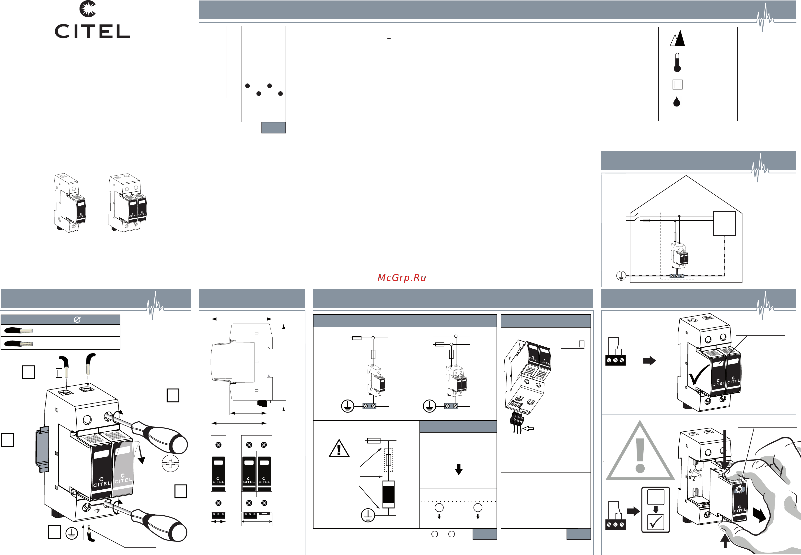
INSTALLATION INSTRUCTIONS -
NOTICE D'INSTALLATION
NOTICIA DE INSTALACIÓN - INSTALLATIONSHINWEISE
ISTRUZIONI PER L'INSTALLAZIONE
INSTRUCOES DE INSTALACAO - MONTÁŽNÍ NÁVOD
РУКОВОДСТВО ПО МОНТАЖУ - 安装指导书
DDC30 series
N170901c
* Note: take off the protection film if needed
5
2.0 - 2.5 Nm
17.8 - 22.1 Lb-In
1
2
4
16 mm
0.63 in
Clip on
symmetrical
DIN rail
3
2.0 - 2.5 Nm
17.8 - 22.1 Lb-In
6 mm² min.
Cross recess
PZ-2
*
+/-
-/+
DC power
source
protected
equipment
F1
F2
Note: take off the protection film
if needed (see below)
Application example
+
-
PE
Fuses to use :
50 A min. - 125 A max.
DC surge protector -
Parafoudre DC
Überspannungsschutz für DC - DC contra sobret
Protezione DC - Proteção DC - Svodiče přepěti pro DC
Устройство защиты от импульсных
перенапряжений для сетей DC - 直流浪涌保护器
Installation Maintenance
Wiring
Dimensions (mm)
2.5 - 35 mm
2
13 - 2 AWG
2.5
- 25 mm
2
13 - 4 AWG
min-max
11-12 Closed = SPD OK
11-14 Open = SPD OK
Remote signal for
disconnection information
11-12 Open = SPD disconnect
11-14 Closed = SPD disconnect
Remote contact wiring
** depending on national rules : Solution or
Table 2
F1 ≤ 50 A
F1 > 50 A
F2
No F2
=
50 A
Standard wiring
Fuses Type gG
GREEN indicator
Remote signal for
disconnection information
Remote contact wiring
Table 3Table 3
1,5 mm²
# 14 AWG max
2.1 Lb-In
0,5 Nm max.
250 Vac / 0.5 A max.
30 Vdc / 3 A max.
OK
DEFECT
Replace with
MDDC30-xxx
1 2
F2 ≤ F1
1 2
** **
12
11
14
44
90
7
67
73.5
18
X
a
b
c
F2
F1
∑
a+b+c
≤ 50 cm
≤ 20 inch
SPD
X
NOT Green indicator
Press
Press
DDC30S
12
11
14
+/-
F2
PE
F1
+
-
F2
PE
F1
36
Technical Data
Table 1
Remote signal option: S: e.g DDC30S-20-65
48 Vdc
75 Vdc
Ipe (per pole)
I
sccr (per pole)
I
max (per pole)
DC network (Un)
Wiring
NA
30 kA
DDC30(S)-10-65
DDC30(S)-10-85
DDC30(S)-20-65
DDC30(S)-20-85
< 1 mA
+/-
+/-
6500 ft max.
2000 m ma
x.
-40/+185°F max.
-40/+85°C max.
IP20 (built in)
indoor use only
Humidity range
5% to 95%
Number of ports : 1
Содержание
- 12 closed spd ok 11 14 open spd ok 1
- 12 open spd disconnect 11 14 closed spd disconnect 1
- Application example 1
- Dc network un 1
- Ddc30 series 1
- Defect 1
- F1 50 a 1
- Fuses to use 50 a min 125 a max 1
- Fuses type gg 1
- Installation maintenance wiring dimensions mm 1
- Min max 1
- N170901c 1
- Remote contact wiring 1
- Standard wiring 1
- Technical data 1
- Wiring 1
- Atencion atencion 2
- Attention 2
- Attenzione 2
- Fr de pl si 2
- Let op 2
- Varování 2
- Warnung 2
- Внимание 2
- 中文 2
- 安全须知 2
Похожие устройства
- CITEL DDC30-10-85 Инструкция по установке
- CITEL DDC30-20-65 Инструкция по установке
- CITEL DDC30-20-85 Инструкция по установке
- CITEL DS210-110DC Инструкция по установке
- CITEL DS210-12DC Инструкция по установке
- CITEL DS210-130DC Инструкция по установке
- CITEL DS210-24DC Инструкция по установке
- CITEL DS210-48DC Инструкция по установке
- CITEL DS210-75DC Инструкция по установке
- CITEL DS210-95DC Инструкция по установке
- CITEL DS41S-48DC Инструкция по установке
- CITEL DS41S-75DC Инструкция по установке
- CITEL DS42S-48DC Инструкция по установке
- CITEL DS42S-75DC Инструкция по установке
- CITEL DS50VGPV-1000G/12KT1 Инструкция по установке
- CITEL DS60VGPV-1000G/51 Инструкция по установке
- CITEL DS60VGPV-1500G/51 Инструкция по установке
- CITEL DS60VGPV-600G/51 Инструкция по установке
- CITEL DS50PV-1000G/12KT1 Инструкция по установке
- CITEL PPV1-6S-10-600 Инструкция по установке