
DC COMPONENTS 1A2-DC Инструкция по эксплуатации онлайн
1A1
THRU
1A7
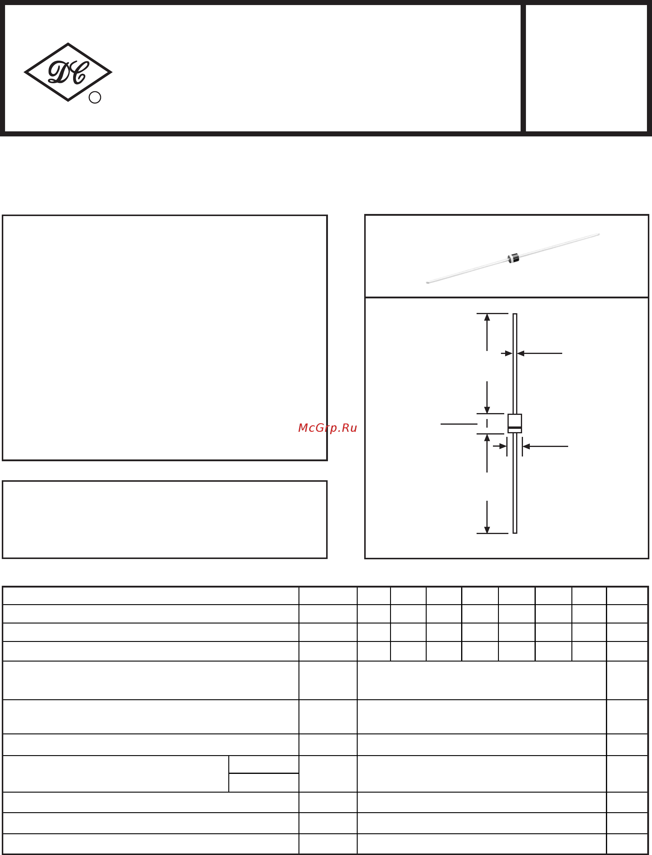
Dimensions in inches and (millimeters)
FEATURES
MECHANICAL DATA
*High reliability
*Low leakage
*Low forward voltage drop
*High current capability
*Case: Molded plastic
* Epoxy: UL 94V-0 rated flame retardant
*Lead: MIL-STD-202E, Method 208 guaranteed
*Polarity: Color band denotes cathode end
* Mounting position: Any
*Weight: 0.19 gram approx.
RECTIFIER SPECIALISTS
R
DC COMPONENTS CO., LTD.
Maximum Recurrent Peak Reverse Voltage
Maximum RMS Voltage
Maximum DC Blocking Voltage
Peak Forward Surge Current 8.3 ms single half sine-wave
superimposed on rated load (JEDEC Method)
Operating and Storage Temperature Range
Volts
Amps
1.0
30
-55 to +150
UNITS
Typical Thermal Resistance
(Note 2)
50
1.1
5.0
Maximum DC Reverse Current at Rated
DC Blocking Voltage
Maximum Instantaneous Forward Voltage at 1.0A DC
µAmps
@ TA=25
o
C
@ TA=100
o
C
1A1 1A2 1A3
1A4 1A5 1A6 1A7
35 70 140
280 420 560 700
50 100 200
400 600 800 1000
50 100 200
400 600 800 1000
o
C/W
Typical Junction Capacitance (Note 1)
15
pF
Maximum Average Forward Rectified Current
375"(9.5mm) lead length
at T
A
= 50 C
o
50
o
C
Volts
Volts
Amps
Volts
MAXIMUM RATINGS AND ELECTRICAL CHARACTERISTICS
Ratings at 25 C ambient temperature unless otherwise specified.
Single phase, half wave, 60Hz, resistive or inductive load.
For capacitive load, derate current by 20%.
R-1
.787(20.0)
MIN.
.102(2.6)
.087(2.2)
.138(3.5)
.114(2.9)
.028(0.7)
.020(0.5)
.787(20.0)
MIN.
DIA.
DIA.
SYMBOL
V
RRM
V
DC
I
O
I
FSM
T
J
,T
STG
V
RMS
Rθ
JA
V
F
I
R
C
J
REV-3,MAY,2017 www.dccomponents.com1
o
Note 1: Measured at 1 MHz and applied reverse voltage of 4.0 volts.
Note 2: Typical thermal resistance from junction to ambient.
TECHNICAL SPECIFICATIONS OF GENERAL PURPOSE SILICON RECTIFIER
VOLTAGE RANGE - 50 to 1000 Volts CURRENT - 1.0 Ampere
Содержание
Похожие устройства
- DC COMPONENTS 1A3-DC Инструкция по эксплуатации
- DC COMPONENTS 1A4-DC Инструкция по эксплуатации
- Sennheiser Set 860 Краткая инструкция
- Sennheiser Set 860 Инструкция
- DC COMPONENTS 1A5-DC Инструкция по эксплуатации
- DC COMPONENTS 1A6-DC Инструкция по эксплуатации
- DC COMPONENTS 1A7-DC Инструкция по эксплуатации
- DC COMPONENTS 10A1-DC Инструкция по эксплуатации
- DC COMPONENTS 10A2-DC Инструкция по эксплуатации
- DC COMPONENTS 10A4-DC Инструкция по эксплуатации
- DC COMPONENTS 10A6-DC Инструкция по эксплуатации
- DC COMPONENTS 10A8-DC Инструкция по эксплуатации
- DC COMPONENTS 6A1M-DC Инструкция по эксплуатации
- DC COMPONENTS 6A2M-DC Инструкция по эксплуатации
- DC COMPONENTS 6A4M-DC Инструкция по эксплуатации
- DC COMPONENTS 6A6M-DC Инструкция по эксплуатации
- DC COMPONENTS 6A8M-DC Инструкция по эксплуатации
- DC COMPONENTS 10A05-DC Инструкция по эксплуатации
- DC COMPONENTS 10A10-DC Инструкция по эксплуатации
- DC COMPONENTS 6A05M-DC Инструкция по эксплуатации